Foreword
Caractéristiques structurelles
Les produits de la série CyberPi sont conçus avec des apparences spéciales, telles que des trous, des trous traversants, des broches et des trous taraudés, qui leur permettent d'être étendus avec d'autres pièces ou composants.
| Conception de l'apparence | Description | |
|---|---|---|
| CyberPi | 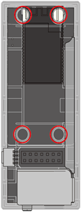 | Des trous à l'arrière, utilisés pour : |
- se connecter à des cartes d'extension
- se connecter à des blocs Lego ou des pièces métalliques M4 de Makeblock à travers des broches |
| Pocket Shield |
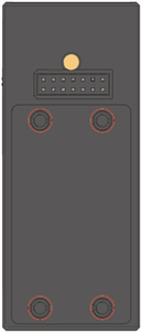 | Des broches à l'avant, utilisées pour se connecter à CyberPi |
| |
| Des broches à l'avant, utilisées pour se connecter à CyberPi |
| |  | Des trous et un trou taraudé à l'arrière.
 - Les trous sont utilisés pour se connecter à des blocs Lego ou des pièces métalliques M4 de Makeblock à travers des broches.
- Le trou taraudé est utilisé pour se connecter à des pièces métalliques M4 de Makeblock à travers des vis. |
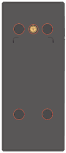
| Modules mBuild |
 | Des trous traversants, utilisés pour se connecter à des pièces métalliques M4 de Makeblock à travers des broches ou des vis, ou à des blocs Lego à travers des broches |
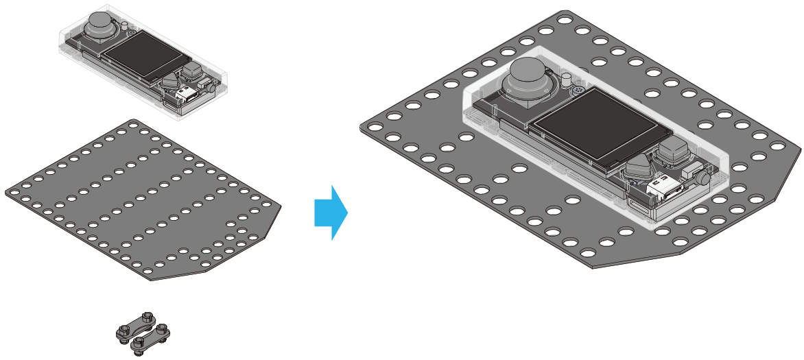
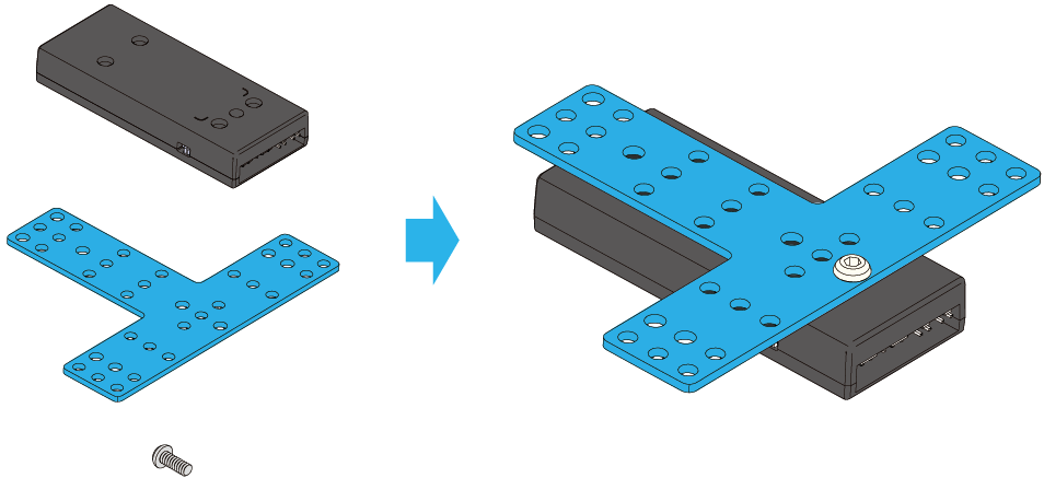
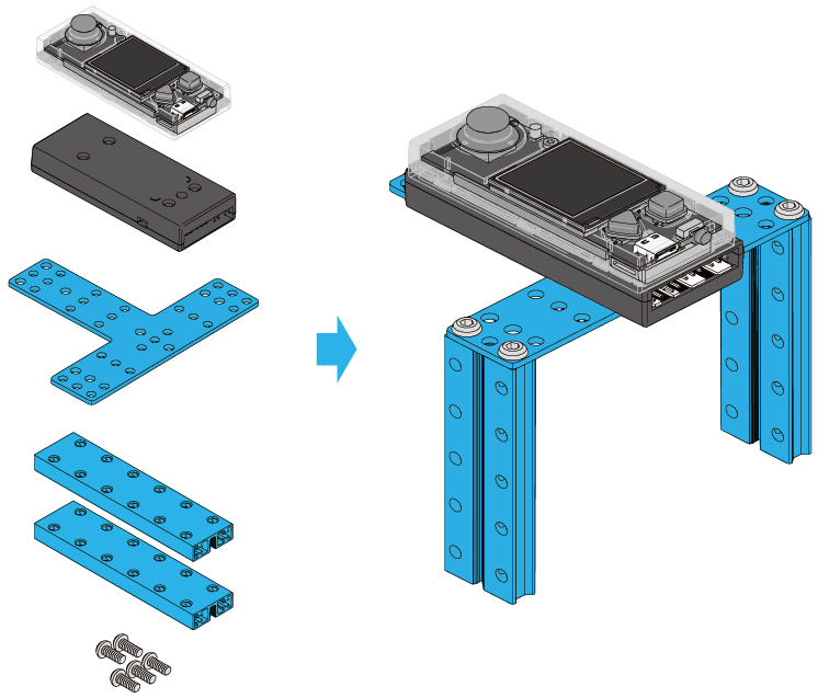
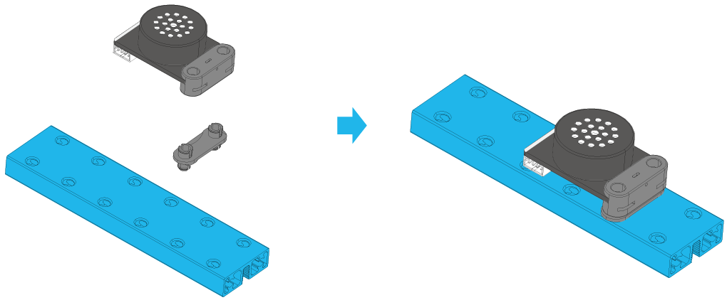
Voici quelques exemples de connexions courantes :
Exemple 1 : CyberPi + une poutre + deux broches
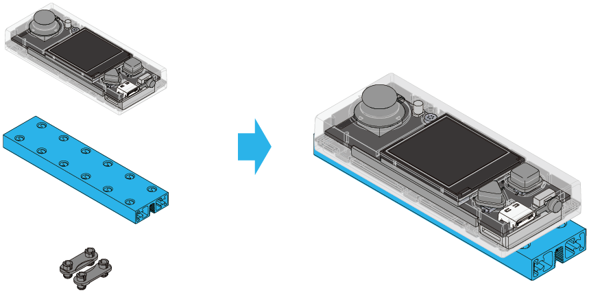
Exemple 2 : CyberPi + une planche coupée + deux broches
Exemple 3 : Pocket Shield + une plaque en forme de T + une vis M4 x 14
Exemple 4 : CyberPi + Pocket Shield + une plaque en forme de T + deux poutres + cinq vis
Pour plus d'informations sur les pièces métalliques de Makeblock, consultez Pièces mécaniques sur la plateforme Maker.
- Source: Caractéristiques structurelles
Caractéristiques électroniques
Carte de contrôle principale
CyberPi

Cartes d'extension
CyberPi peut fonctionner avec plusieurs cartes d'extension pour répondre à divers besoins éducatifs.
Pocket Shield
 Pour plus d'informations sur le Pocket Shield, consultez Pocket Shield.
D'autres cartes d'extension sont en cours de développement. Restez à l'écoute !
Modules électroniques
En plus des modules électroniques mBuild, la série CyberPi prend en charge les composants et pièces électroniques tiers, par exemple, les modules Arduino.
Modules électroniques mBuild
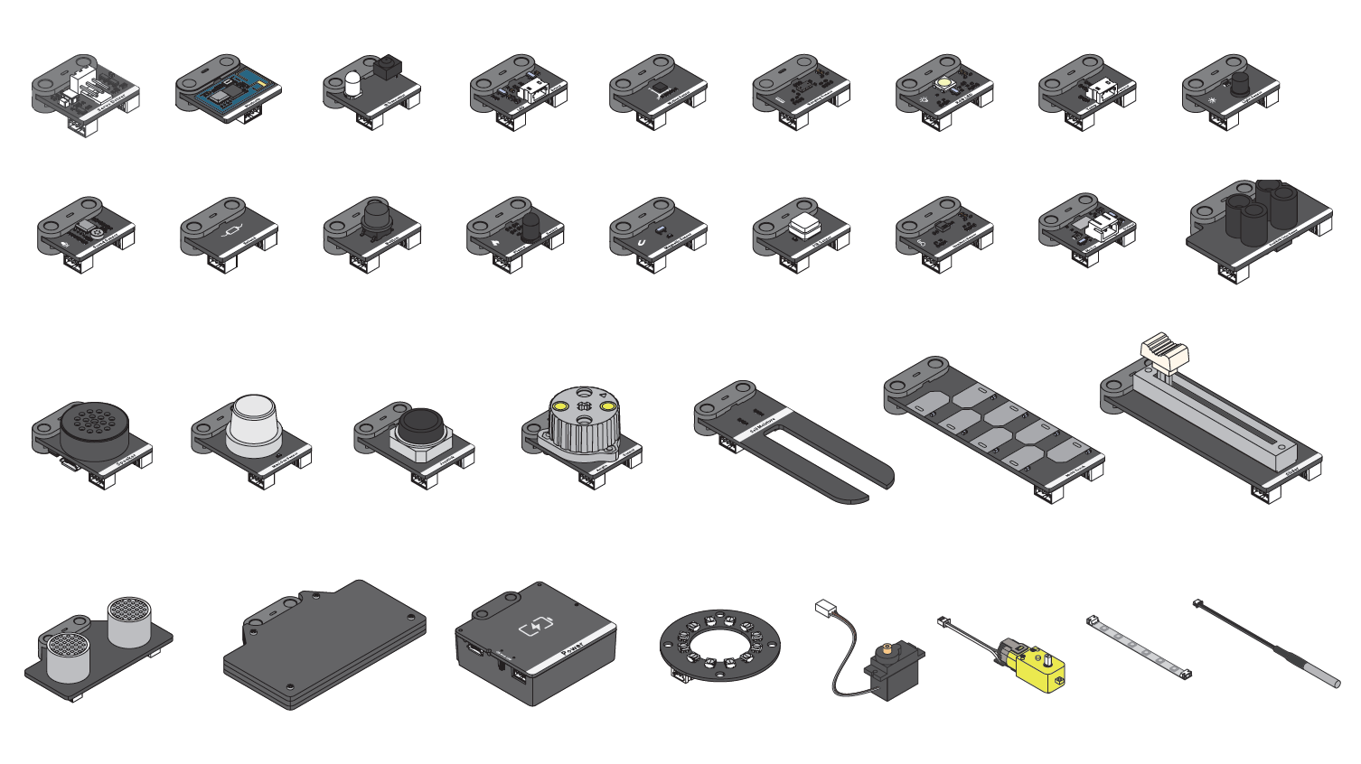 Actuellement, plus de 30 modules électroniques mBuild ont été développés, et d'autres modules seront disponibles.
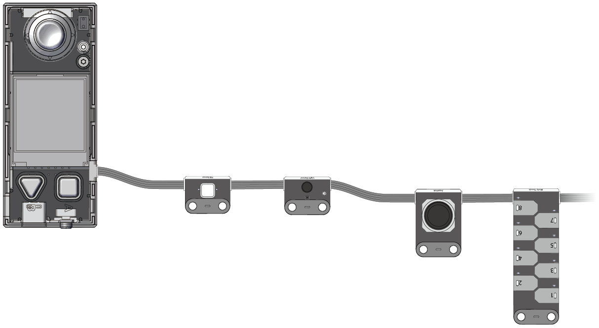
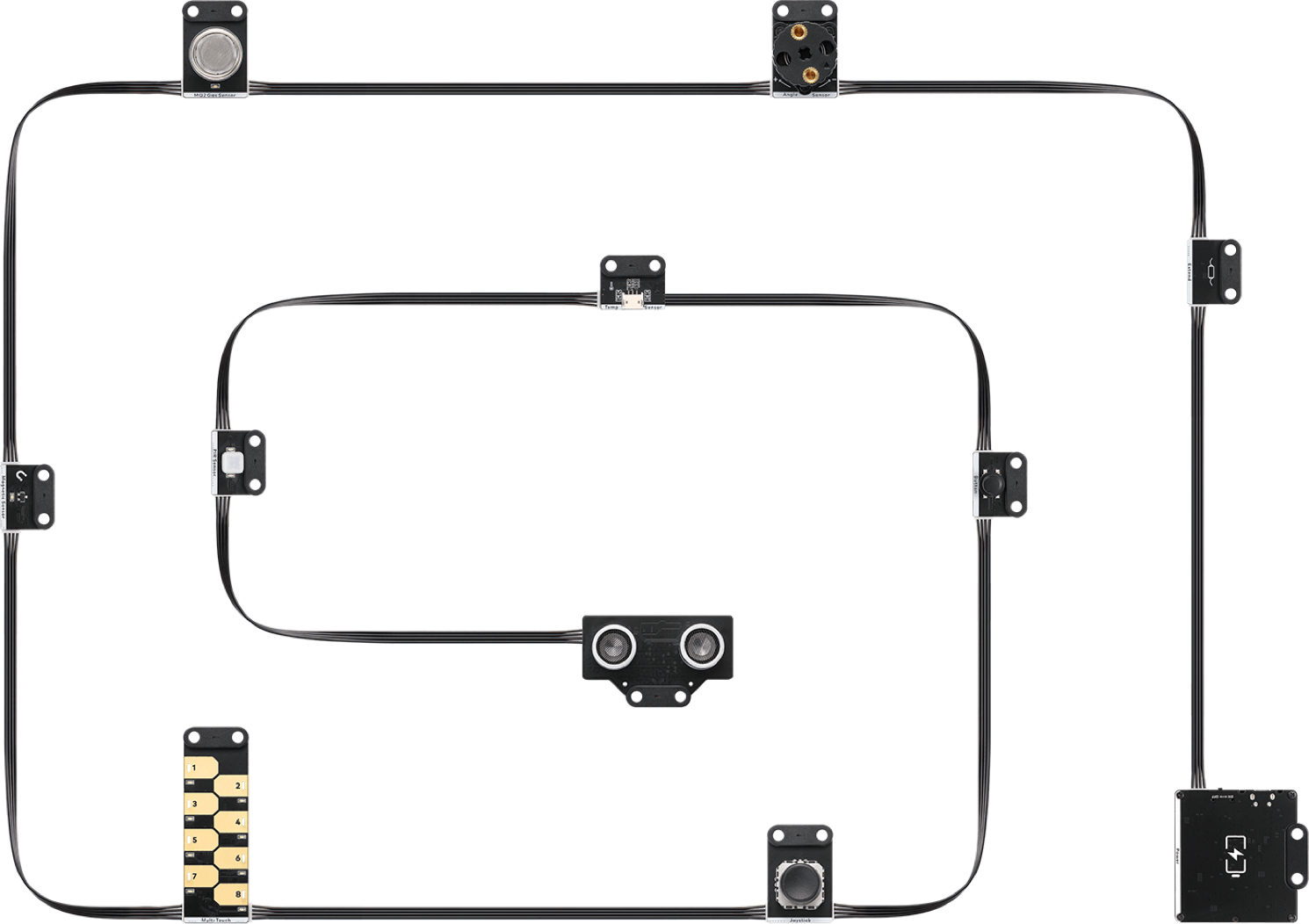
Chaque module mBuild est équipé d'une puce de microtraitement, ce qui permet à plusieurs modules de se connecter en série à un seul port, comme le montre la figure suivante.
 De plus, mBlock 5 peut identifier intelligemment l'adresse des modules, ce qui simplifie votre programmation. Vous n'avez pas à définir les informations sur l'adresse des modules dans l'environnement de programmation lorsque vous ajoutez ou supprimez un module.
Identification intelligente de l'adresse
**Exemple: **
Connecter CyberPi à plusieurs matrices LED
 Après avoir connecté CyberPi à plusieurs matrices LED, vous devez uniquement spécifier l'emplacement d'une matrice LED parmi celles connectées au lieu de spécifier le port auquel la matrice LED est connectée lors de la compilation d'un programme. Comme le montre la figure précédente, la première matrice LED connectée à CyberPi est numérotée 1, la deuxième est numérotée 2, et ainsi de suite.
 Lorsque vous appuyez sur le bouton A sur CyberPi, la première matrice LED affiche "Hello", et la deuxième affiche "World".
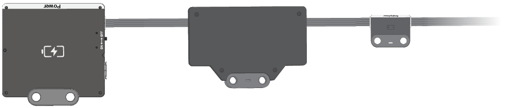
Changez les positions des modules, comme le montre la figure suivante.
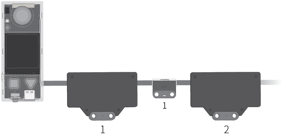 Le programme précédent fonctionne toujours après avoir ajouté un capteur de distance. Lorsque vous appuyez sur le bouton A sur CyberPi, la première matrice LED affiche "Hello", et la deuxième affiche "World".
Pour plus d'informations, voir Modules électroniques mBuild.
Capteurs tiers
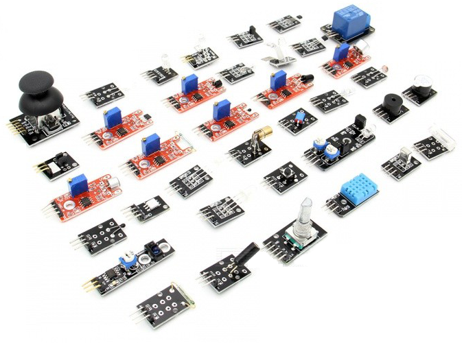 (Source: Page Web Internet)
La série CyberPi est compatible avec plusieurs capteurs tiers. Vous pouvez consulter les Matériaux open source pour comprendre comment les produits de la série CyberPi sont connectés aux composants électroniques ou pièces tierces.
Moteurs
En travaillant en combinaison avec les modules électroniques ou les cartes d'extension correspondantes, CyberPi peut piloter plusieurs types de moteurs. Le tableau suivant décrit les moteurs pris en charge par CyberPi.
| Support | À travers les modules mBuild | À travers le Pocket Shield | À travers la carte mBot2 | À travers la carte d'extension Challenge |
|---|---|---|---|---|
| Moteur TT 5V | Oui | Oui | Oui | Oui |
| Servo 9g 5V | Oui | Oui | Oui | Oui |
| Servo intelligent 6–12V | Oui | Oui | Oui | Oui |
| Moteur à codeur 12V | Oui | Oui | ||
| Moteur sans balais | Oui | |||
| Moteur pas à pas | Oui |
Autres accessoires
Contrôleur Bluetooth
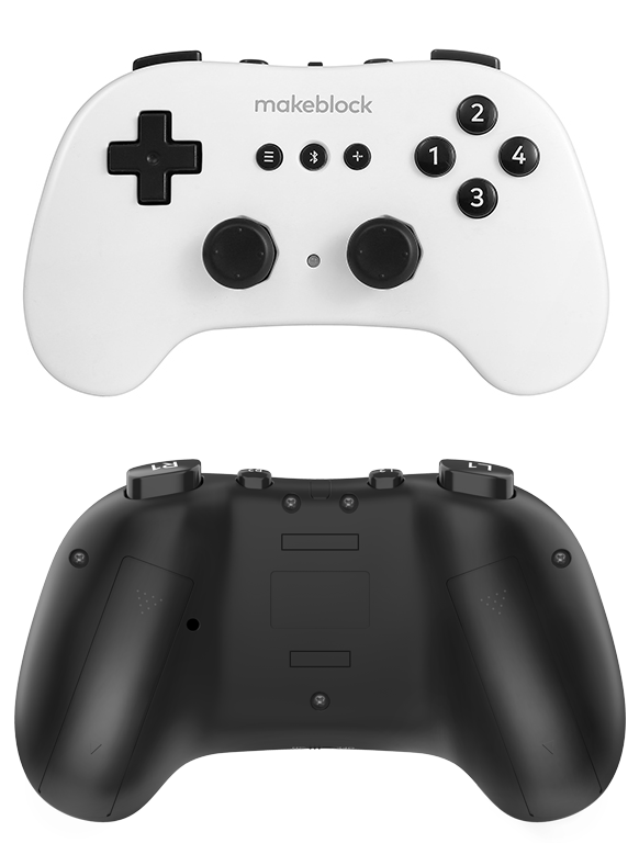
Les produits de la série CyberPi peuvent se connecter au contrôleur Bluetooth de Makeblock pour l'utiliser comme télécommande. Pour plus d'informations sur le contrôleur Bluetooth de Makeblock, consultez Aide en ligne du contrôleur Bluetooth.
Dongle Bluetooth
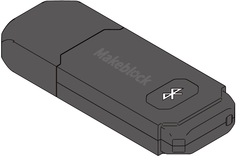
Les produits de la série CyberPi peuvent se connecter à des PC en utilisant le dongle Bluetooth de Makeblock. Pour plus d'informations sur le dongle Bluetooth de Makeblock, consultez Guide de démarrage rapide du dongle Bluetooth.
Types de ports
Les produits de la série CyberPi sont conçus avec plusieurs ports, ce qui leur permet de se connecter facilement à d'autres composants électroniques et pièces, facilitant l'extension de nombreuses fonctions.
| Ports | Description | |
|---|---|---|
| CyberPi | 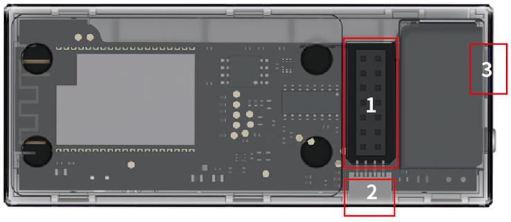 | 1: utilisé pour connecter des cartes d'extension |
| 2: utilisé pour connecter des modules électroniques mBuild | ||
| 3: câble USB de type C, utilisé pour connecter un PC | ||
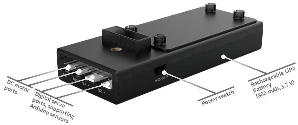
| Pocket Shield | 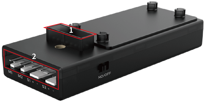 | 1: utilisé pour connecter CyberPi |
| 2: ports de moteurs CC M1 et M2, utilisés pour connecter des moteurs ; ports de servos numériques S1 et S2, utilisés pour connecter des servos ou des bandes LED | ||
| Module électronique mBuild | 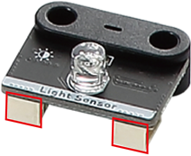 | Utilisé pour connecter une carte de contrôle principale ou d'autres modules électroniques mBuild |
Les exemples d'extension de fonctions courantes suivent :
Exemple 1: Connexion du Pocket Shield à CyberPi
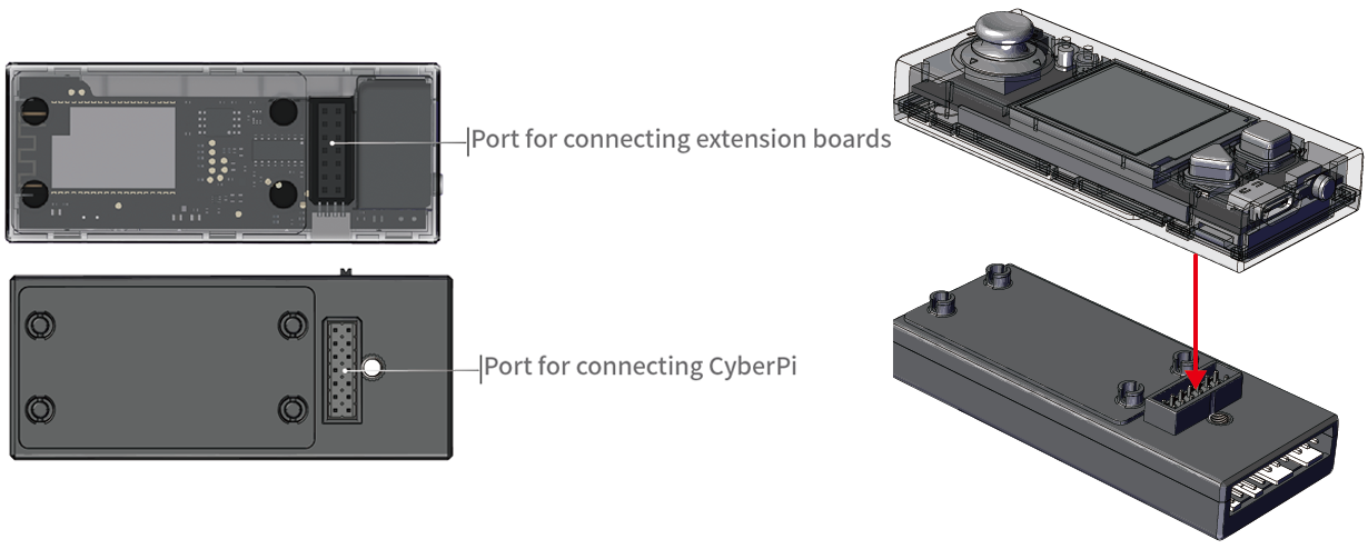 Le Pocket Shield est équipé d'une batterie rechargeable intégrée qui peut alimenter CyberPi et fournit des ports à 2 broches et 3 broches qui peuvent être utilisés pour connecter des servos, des bandes LED et des moteurs, ce qui améliore considérablement l'extensibilité de CyberPi.
Exemple 2: Connexion des modules mBuild à CyberPi
 Les modules mBuild sont petits mais riches en fonctionnalités. CyberPi peut être connecté à plusieurs modules mBuild en connexion série.
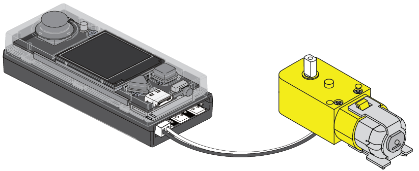
Exemple 3: Connexion d'un moteur à CyberPi via le Pocket Shield
CyberPi peut se connecter à plusieurs types de moteurs via d'autres modules ou cartes d'extension.
Câbles
Les produits de la série CyberPi prennent en charge plusieurs types de câbles de connexion, comme décrit dans le tableau suivant.
| Nom | Description |
|---|---|
| Câble USB de type C | Utilisé pour connecter CyberPi à des PC pour l'alimentation ou la transmission de programmes/commandes |
| Câble à 4 broches | Utilisé pour connecter les modules mBuild |
| Câble à 3 broches | Utilisé pour connecter le Pocket Shield ou la carte mBot2 aux bandes LED |
| Utilisé pour connecter les pilotes de LED mBuild aux bandes LED | |
| Câble à 2 broches | Utilisé pour connecter le Pocket Shield ou la carte mBot2 aux moteurs CC |
| Utilisé pour connecter les pilotes de moteurs mBuild aux moteurs CC |
- Source: Caractéristiques électroniques
Programmation de CyberPi sur Chromebook
Installer mLink sur Chromebook et démarrer mBlock 5
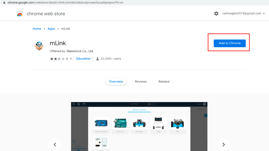
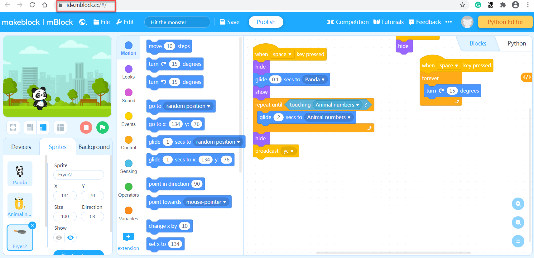
Étape 1: Veuillez accéder à ce lien et trouver mLink pour Chromebook (besoin de faire défiler la page vers le bas).
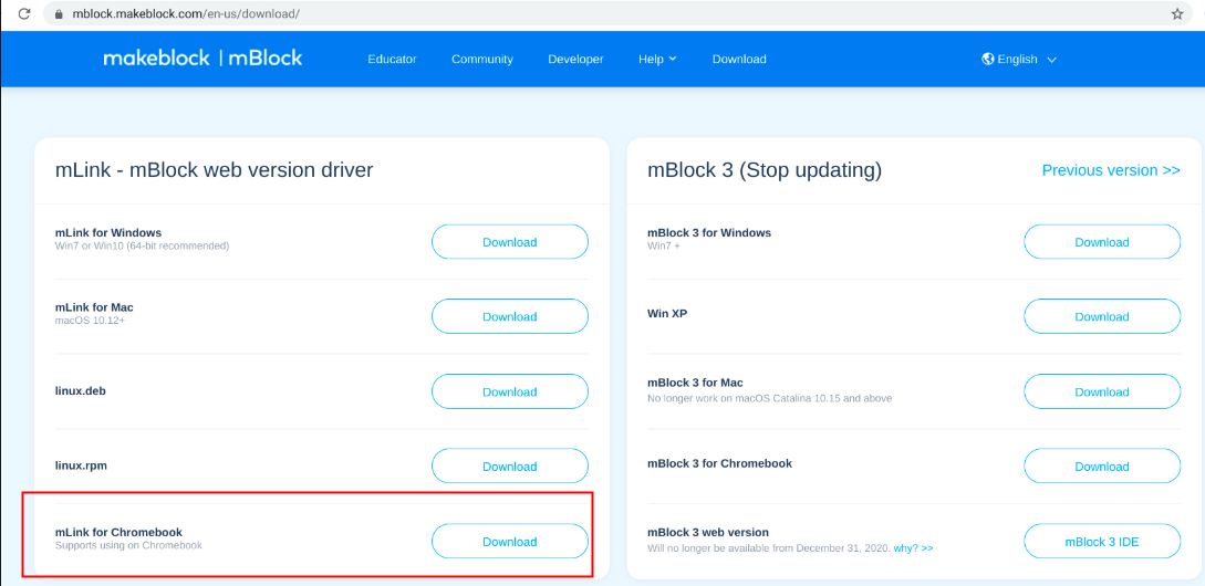 Étape 2: Veuillez cliquer sur "Télécharger" pour accéder au Chrome Web Store, puis cliquez sur "Ajouter à Chrome" pour installer mLink.
:::info
Remarque: Si vous avez déjà installé mLink auparavant, vous verrez directement l'option "Lancer l'application" et vous pouvez contourner l'étape 2.
:::
Étape 2: Veuillez cliquer sur "Télécharger" pour accéder au Chrome Web Store, puis cliquez sur "Ajouter à Chrome" pour installer mLink.
:::info
Remarque: Si vous avez déjà installé mLink auparavant, vous verrez directement l'option "Lancer l'application" et vous pouvez contourner l'étape 2.
:::
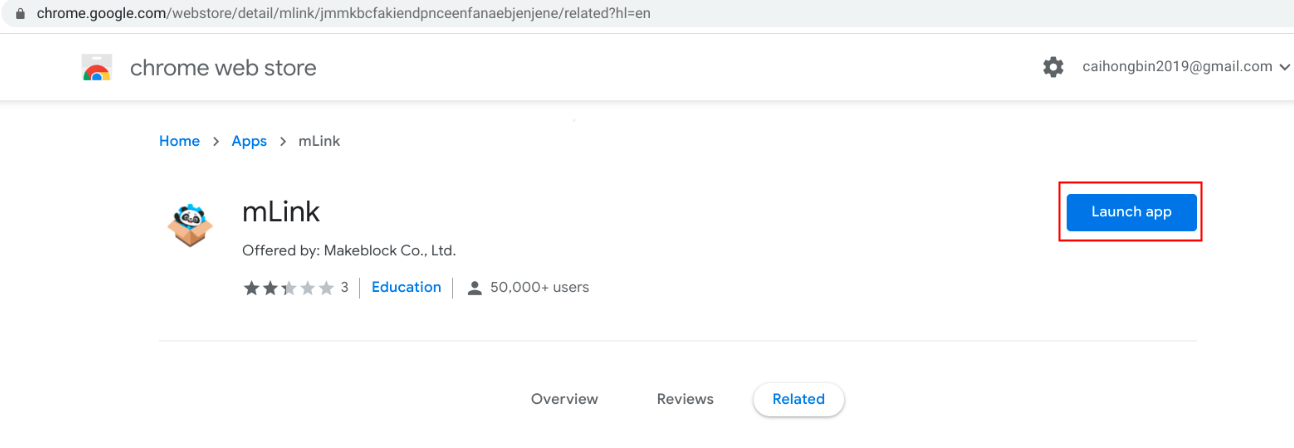
 Ensuite, une fenêtre s'ouvrira, il suffit de cliquer sur "Ajouter l'application", et l'option "Lancer l'application" sera disponible.

 :::info
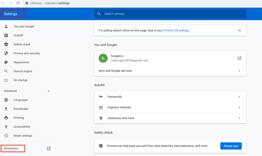
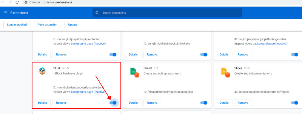
Remarque: Si vous ne trouvez pas l'option "Lancer l'application" après avoir installé mLink, veuillez vérifier si mLink est activé en allant dans "Paramètres"->"Extensions".
:::
:::info
Remarque: Si vous ne trouvez pas l'option "Lancer l'application" après avoir installé mLink, veuillez vérifier si mLink est activé en allant dans "Paramètres"->"Extensions".
:::
 Étape 3: Cliquez sur "Lancer l'application" et vous accéderez à la version Web du logiciel mBlock 5 :
Connecter CyberPi à mBlock 5 sur Chromebook
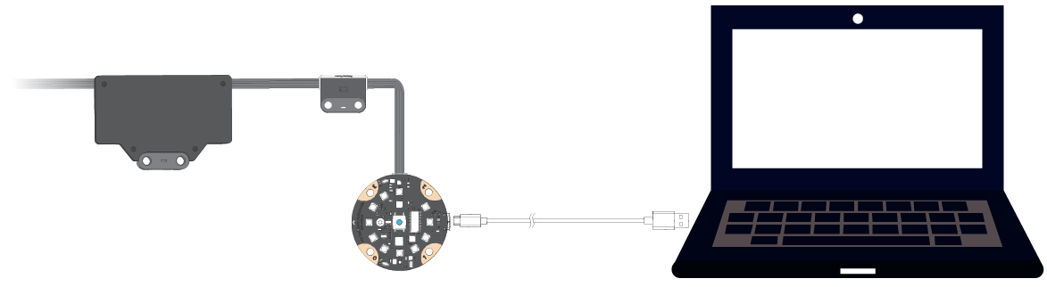
Étape 1: Connectez CyberPi au Chromebook avec un câble USB.
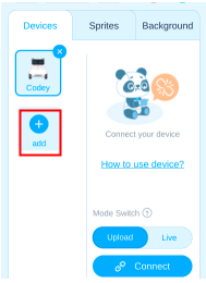
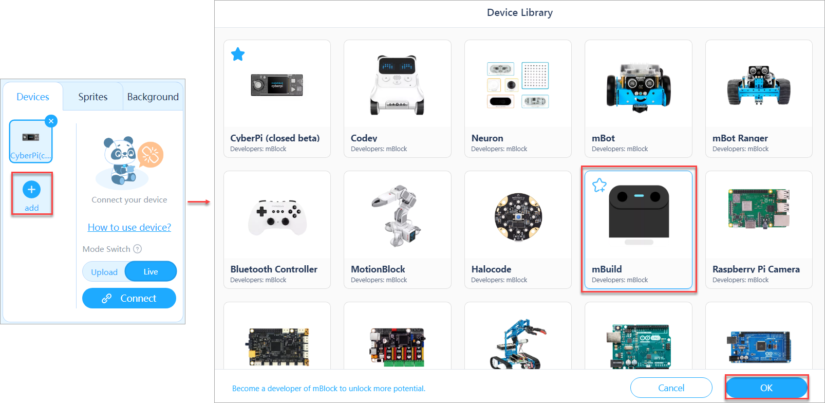
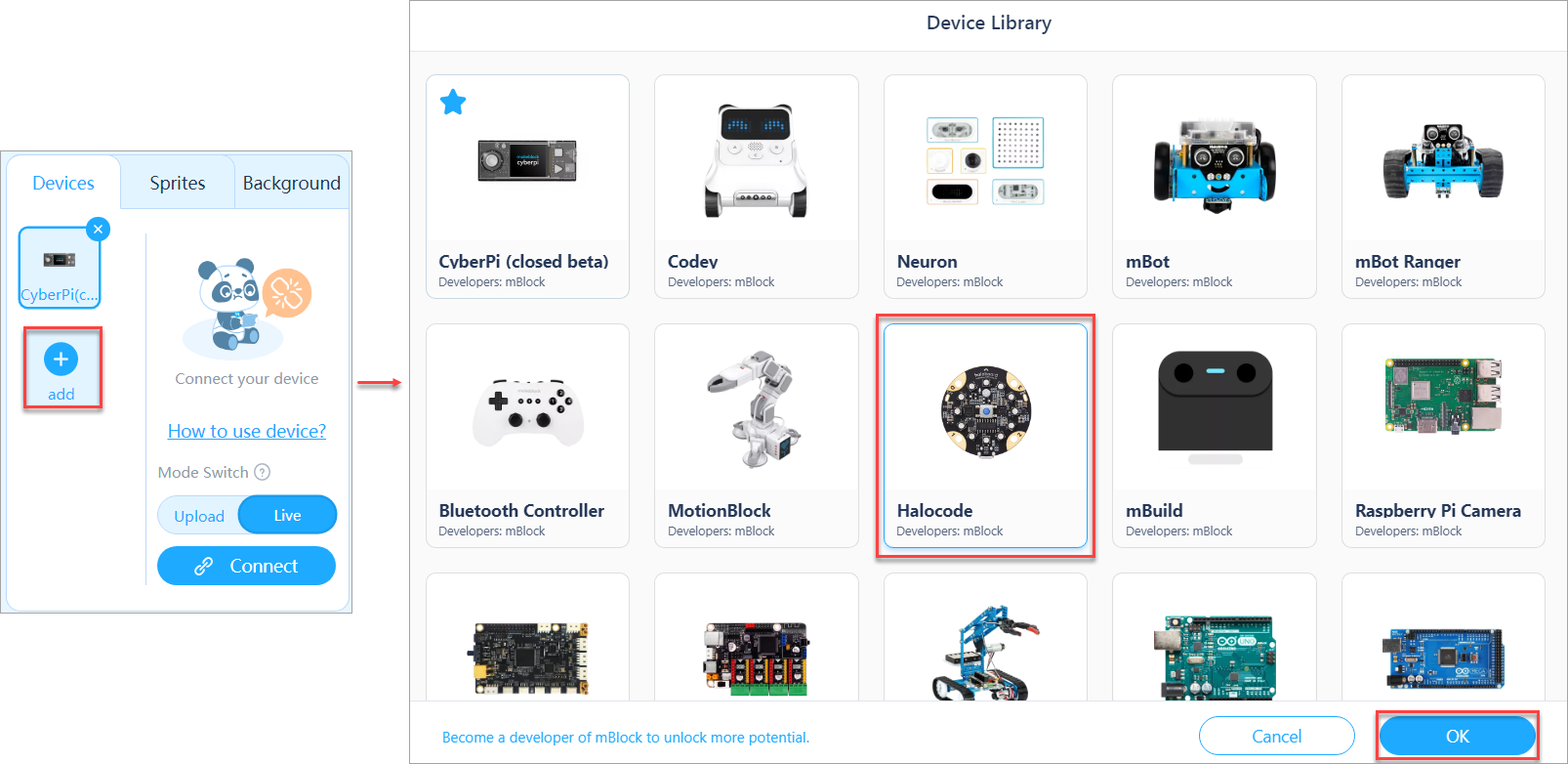
Étape 2: Cliquez sur l'icône "+" pour ouvrir la bibliothèque de périphériques :
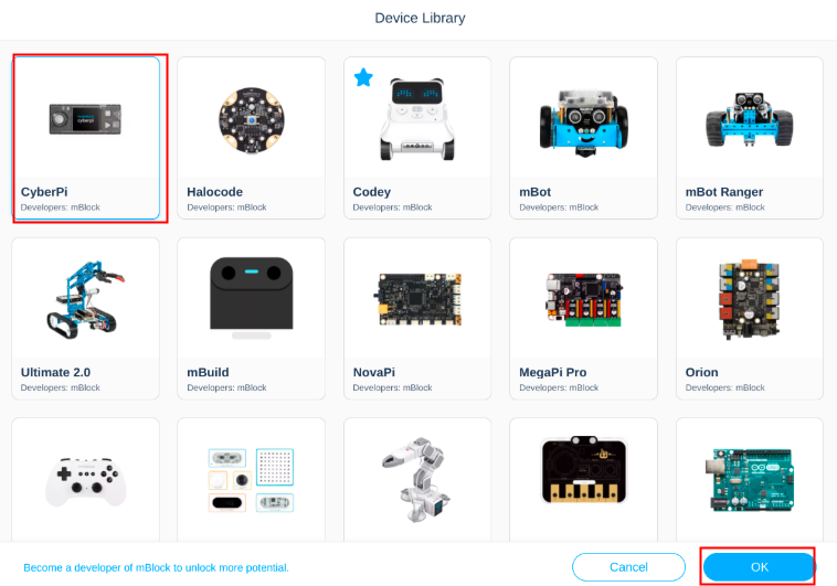
 Étape 3: Trouvez le périphérique "CyberPi" et sélectionnez-le, puis cliquez sur "Ok" et vous verrez que le périphérique CyberPi est ajouté sous "Périphériques" :
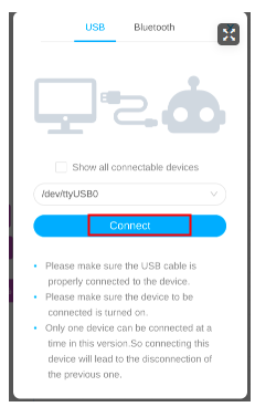
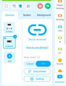
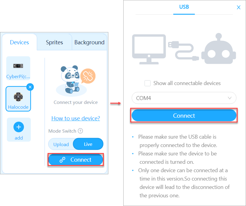
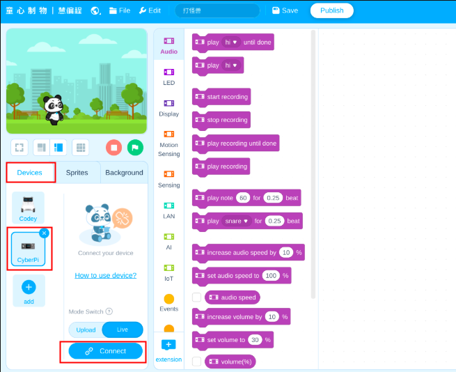 Étape 4: Cliquez sur l'icône "Connecter" et une fenêtre de connexion s'affiche, normalement, le port série pour CyberPi sera disponible automatiquement, veuillez simplement cliquer sur "Connecter" et vous verrez le statut après connexion.
Programmation de CyberPi avec mBlock 5 sur Chromebook
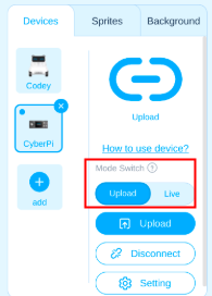
Mode en direct
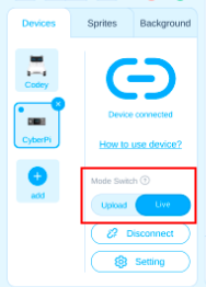
Étape 1: Assurez-vous que le Commutateur de mode est tiré sur "Live"
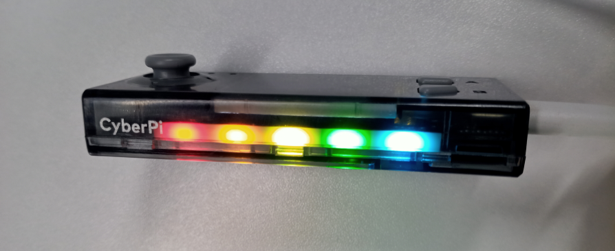
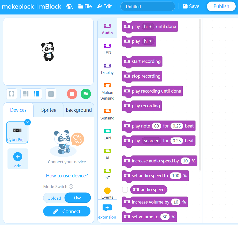
 Étape 2: Faites glisser un programme simple pour tester CyberPi (ici, je fais simplement glisser le bloc display[][][][][] pour tester les LED sur CyberPi à titre d'exemple).
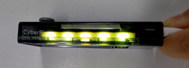
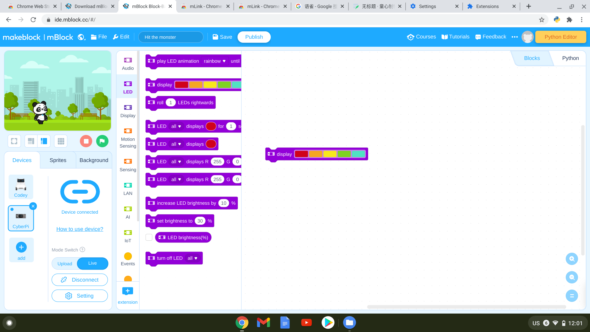 Étape 3: Cliquez sur le bloc de programme et vous verrez la réaction des LED sur le périphérique CyberPi.
Mode de téléversement
Étape 1: Basculez le Commutateur de mode sur "Upload".
 Étape 2: Éditez un programme simple (une tête de programme de la catégorie d'événement est nécessaire) et cliquez sur "Téléverser"
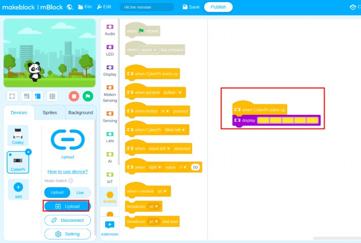 Étape 3: Maintenant, vous verrez la réaction des LED sur le périphérique CyberPi après que le programme a été téléversé avec succès.
- Source: Programmation sur Chromebook
Related Education System
Coming soon!
À propos de CyberOS
CyberOS est le système d'exploitation qui fonctionne sur CyberPi. Il est le composant principal qui prend en charge toutes les fonctions de CyberPi.
Accéder à la page d'accueil de CyberOS
CyberPi fonctionne sous CyberOS. Après la mise sous tension, CyberPi affiche la page d'accueil du système. Si la page d'accueil n'est pas affichée, vous pouvez appuyer sur le bouton Accueil situé sur le côté droit de CyberPi pour y accéder.

Après le démarrage de CyberOS, vous pouvez utiliser les programmes prédéfinis, définir la langue du système et le mettre à jour via Internet.
Vous pouvez quitter la page d'accueil en choisissant "Redémarrer le programme", et le système exécutera automatiquement le dernier programme que vous avez exécuté.
:::info **Note : **Lorsque CyberPi est connecté à mBlock 5 et programmé en mode Live, le bouton ACCUEIL ne fonctionne pas et vous ne pouvez pas accéder à la page d'accueil en appuyant dessus. :::
Définir la langue du système
Si la langue par défaut du système n'est pas votre langue maternelle, vous pouvez la modifier. Les étapes suivantes décrivent la procédure pour changer la langue de l'anglais au chinois :
- Accédez à la page d'accueil, sélectionnez Paramètres en déplaçant le joystick vers le haut ou vers le bas, puis appuyez sur le bouton B pour accéder à la page Paramètres.

- Sur la page Paramètres, sélectionnez Langue en déplaçant le joystick vers le haut ou vers le bas, puis appuyez sur le bouton B pour accéder à la page Langue.
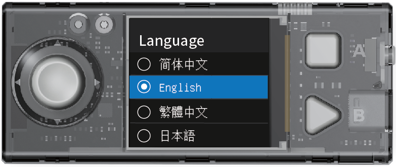
- Sur la page Langue, sélectionnez 简体中文 en déplaçant le joystick vers le haut ou vers le bas, puis appuyez sur le bouton B pour terminer la configuration.

Après avoir défini une langue, le système passe à cette langue et revient à la page d'accueil.
Changer de programme
CyberPi peut stocker plusieurs programmes et vous pouvez passer de l'un à l'autre. De plus, CyberPi est livré avec plusieurs programmes d'exemple par défaut pour vous aider à comprendre ses fonctions principales.
:::info Note :
- L'accès à Internet est requis pour les programmes AI et IoT, ils ne sont donc pas inclus dans les programmes d'exemple par défaut et sont fournis dans les programmes d'exemple sur mBlock 5. Trouvez-les en choisissant Tutoriels > Programmes d'exemple sur mBlock 5.
- Le programme que vous téléchargez sur CyberPi sur mBlock 5 remplace celui que vous avez utilisé la dernière fois. Les programmes d'exemple par défaut sont fournis, et vous pouvez les restaurer en les téléchargeant sur votre CyberPi. :::
- Accédez à la page d'accueil, sélectionnez Changer de programme en déplaçant le joystick vers le haut ou vers le bas, puis appuyez sur le bouton B pour accéder à la page Changer de programme.

- Sur la page Changer de programme, sélectionnez un programme, par exemple Programme1, en déplaçant le joystick vers le haut ou vers le bas, puis appuyez sur le bouton B. CyberPi redémarre et exécute le programme 1.

CyberPi affiche d'abord le nom du programme, puis vous invite à effectuer les étapes requises pour exécuter le programme.
Afficher le niveau de la batterie et l'état de la connexion sans fil
Pour afficher le niveau de la batterie et l'état de la connexion sans fil de CyberPi, vous pouvez vous rendre sur sa page d'accueil et consulter l'icône ou les icônes dans le coin supérieur droit. L'icône du niveau de la batterie indique si la batterie est faible, et une icône Wi-Fi s'affiche si CyberPi est connecté à Internet via Wi-Fi.
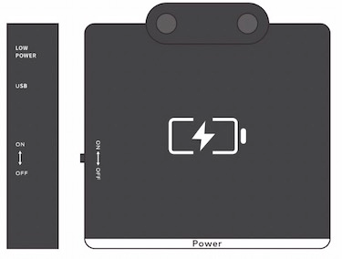
Indication de charge
Lorsque CyberPi est en charge via le câble USB (Type-C), CyberOS affiche une indication de charge :
- Si l'interrupteur d'alimentation est allumé, l'indication se trouve dans le coin supérieur droit de l'écran.
- Si l'interrupteur d'alimentation n'est pas allumé, l'indication s'affiche au centre de l'écran et disparaît au bout de 10 secondes pour faciliter la charge rapide.
Mémorisation des paramètres Wi-Fi et mise à jour du micrologiciel OTA
CyberOS enregistre automatiquement les informations sur les réseaux Wi-Fi que vous avez déjà configurés. (Vous pouvez configurer un réseau Wi-Fi sur mBlock 5 ou l'application Makeblock).
Lorsque CyberPi est connecté à Internet, vous pouvez choisir Mettre à jour sur la page Paramètres pour mettre à jour le micrologiciel en mode OTA (Over-The-Air). CyberOS vérifie automatiquement si la version actuelle est la plus récente et vous invite à mettre à jour le micrologiciel si ce n'est pas le cas.
Texte original : https://www.yuque.com/makeblock-help-center-en/cyberpi/cyberos
mBot2 Shield
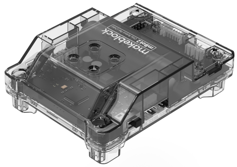
Présentation
Le mBot2 Shield est équipé d'une batterie lithium-ion rechargeable intégrée qui peut fournir de l'énergie au CyberPi. Avec ses ports multifonctions, servo et moteur, il peut entraîner des moteurs, des servos et des bandes de LED.
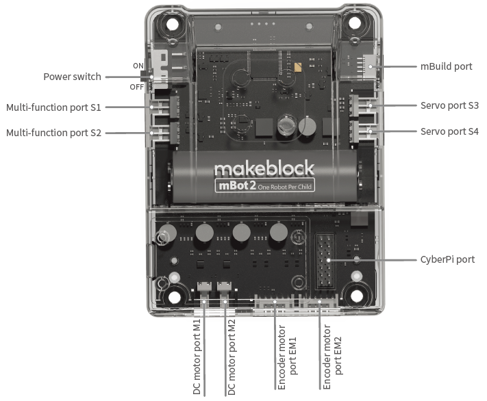
Caractéristiques
- Batterie lithium-ion rechargeable intégrée, utilisée pour alimenter le CyberPi
- Deux ports multifonctions, utilisés pour connecter et piloter non seulement des servos mais aussi des bandes de LED
- Deux ports de servo, utilisés pour connecter et piloter des servos
- Deux ports de moteur à courant continu, utilisés pour connecter et piloter des moteurs à courant continu
- Deux ports de moteur encodeur, utilisés pour connecter et piloter des moteurs encodeurs
- Un port CyberPi, vous permettant de connecter facilement le mBot2 au CyberPi
- Prise en charge de la programmation Python, pour laquelle la bibliothèque
cyberpiest fournie
Spécifications
| Spécification | Description |
|---|---|
| Microprocesseur | GD32F403 |
| Batterie | 3,7 V, 2500 mAh |
| Emballage: Pack (batterie incluse) | |
| Type de batterie: Batterie polymère lithium-ion | |
| Poids de la batterie: 44,6 g | |
| Watt-heures par batterie (Wh): 9,25 Wh | |
| Contenu en lithium: 1,07 g | |
| Tension de la batterie au lithium: 3,7 V | |
| Tension d'entrée et courant | 5 V, 2000 mA (charge rapide) |
| 5 V, 500 mA (charge en fonctionnement) | |
| Tension de sortie et courant | 5 V, 6 A |
| Durée de vie de la batterie | 3 à 6 heures (dans des scénarios d'application générale, à titre de référence uniquement) |
| Temps de charge | 80 minutes (en mode charge rapide) |
| Endurance de la batterie | La capacité de la batterie reste à 70% ou plus après avoir été chargée et utilisée 800 fois (à 20±5°C, décharge de 0,2 C). |
| Mode de communication | Communication série: entre la carte de commande principale et la carte d'extension |
| Signaux numériques: au port de servomoteur numérique | |
| Signaux PWM: au port de moteur à courant continu | |
| Version matérielle | V1.0 |
Remarque:
- L'autodécharge se produit dans la batterie lithium-ion. Si vous stockez le mBot2 Shield avec une tension de batterie inférieure à 3,6 V pendant une longue période, la batterie sera surdéchargée et sa structure interne peut être endommagée, ce qui réduit l'endurance de la batterie. Par conséquent, pour stocker le mBot2 Shield pendant une longue période tout en préservant la batterie, vous devez charger la batterie une fois tous les trois à six mois à 3,8–3,9 V (la meilleure tension de stockage est de 3,85 V), ce qui permet la profondeur de décharge de 40 % à 60 %.
- Stockez le mBot2 Shield entre 4°C et 35°C dans un endroit sec ou éloignez-le de l'humidité grâce à l'emballage.
- Gardez-le à l'abri de la chaleur ou du soleil direct.
Programmation
Vous pouvez utiliser mBlock 5 pour programmer le mBot2. mBlock 5 propose deux éditeurs, à savoir l'éditeur graphique basé sur des blocs (l'éditeur par défaut, appelé mBlock 5) et l'éditeur Python (appelé éditeur mBlock-Python).
Pour plus de détails sur la programmation, consultez "Commencer la programmation."
Ramenez Pocket Shield à la maison
- Contactez le revendeur local pour acheter les produits de la série CyberPi et leurs packs éducatifs.
- Contactez-nous pour devenir notre revendeur.
Plus d'informations
Guide d'utilisation de mBot2 Guide d'utilisation de CyberPi
Pocket Shield
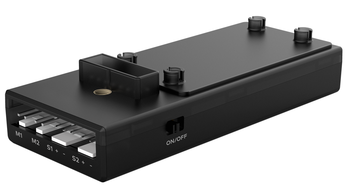
Présentation
Le Pocket Shield est équipé d'une batterie rechargeable intégrée qui peut alimenter le CyberPi et fournit des interfaces à 2 et 3 broches pouvant être utilisées pour connecter des servomoteurs, des bandes de LED et des moteurs, ce qui améliore considérablement l'extensibilité du CyberPi.

Caractéristiques
- Batterie LiPo rechargeable intégrée, utilisée pour alimenter le CyberPi
- Deux ports de moteur à courant continu, utilisés pour connecter et piloter des moteurs à courant continu
- Deux ports de servomoteur numériques, utilisés pour connecter et piloter des servomoteurs ou des bandes de LED
- Un port de carte de commande principale, vous permettant de connecter facilement le Pocket Shield au CyberPi
- Prise en charge de la programmation mBlock 5, destinée aux utilisateurs de tous âges, y compris ceux sans aucune expérience en programmation
- Prise en charge de la programmation Python, pour laquelle la bibliothèque
cyberpiest fournie
Spécifications
| Paramètres du produit | Description |
|---|---|
| Microprocesseur | GD32 |
| Paramètre de la batterie | 3,7V 800mAh |
| Tension/courant d'entrée | 5V 700mA |
| Tension/courant de sortie | 5V 2A |
| Durée de vie de la batterie | 4 heures (dans des scénarios d'application générale, à titre de référence uniquement) |
| Temps de charge | 1 à 2 heures |
| Mode de communication | Communication série : entre la carte de commande principale et la carte d'extension |
| Signaux numériques : au port de servomoteur numérique | |
| Signaux PWM : au port de moteur à courant continu | |
| Version matérielle | V1.1 |
| Dimensions | 84×35×19mm |
| Poids | 48g |
Remarque:
- L'autodécharge se produit dans la batterie LiPo. Si vous stockez le mBot2 Shield avec une tension de batterie inférieure à 3,6 V pendant une longue période, la batterie sera surdéchargée et sa structure interne peut être endommagée, ce qui réduit l'endurance de la batterie. Par conséquent, pour stocker le mBot2 Shield pendant une longue période tout en préservant la batterie, vous devez charger la batterie une fois tous les trois à six mois à 3,8–3,9 V (la meilleure tension de stockage est de 3,85 V), ce qui permet la profondeur de décharge de 40 % à 60 %.
- Stockez le mBot2 Shield entre 4°C et 35°C dans un endroit sec ou éloignez-le de l'humidité grâce à l'emballage.
- Gardez-le à l'abri de la chaleur ou du soleil direct.
Mise à jour du micrologiciel
Après la sortie d'une nouvelle version du micrologiciel, vous pouvez connecter le Pocket Shield à mBlock 5 via CyberPi pour visualiser et mettre à jour son micrologiciel. Pour plus de détails sur la mise à jour du micrologiciel, consultez "Comment mettre à jour le micrologiciel ?"
Programmation
Vous pouvez utiliser mBlock 5 pour programmer le Pocket Shield. mBlock 5 propose deux éditeurs, à savoir l'éditeur graphique basé sur des blocs (l'éditeur par défaut, appelé mBlock 5) et l'éditeur Python (appelé éditeur mBlock-Python).
Pour plus de détails sur la programmation, consultez "Logiciel de programmation."
Ramenez le Pocket Shield chez vous
- Contactez le revendeur local pour acheter les produits de la série CyberPi et leurs packs éducatifs.
- Contactez-nous pour devenir notre revendeur.
Plus d'informations
Guide d'utilisation de CyberPi Guide d'utilisation de Pocket Shield Manuel de l'utilisateur de la série CyberPi Documentation API Python pour CyberPi Aide en ligne de mBlock 5 Aide en ligne de l'éditeur Python de mBlock
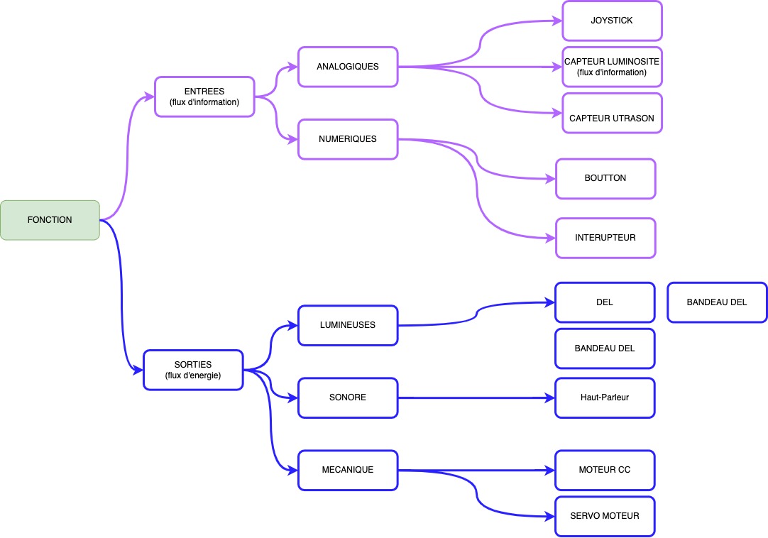
Fonctions et caractéristiques
Fonctions
Les modules mBuild offrent une variété de fonctions d'entrée et de sortie, vous permettant d'étendre facilement les fonctions des cartes principales prises en charge, telles que CyberPi et Halocode.
Caractéristiques structurelles
Tous les modules mBuild sont développés avec deux trous traversants.
Avec les trous traversants, les modules mBuild peuvent être montés les uns sur les autres avec des connecteurs tels que des broches et des vis. De plus, ils peuvent être connectés à des pièces mécaniques (M4), à des blocs de construction et à d'autres pièces structurales à l'aide de connecteurs. Voici quelques exemples de connexion :
Exemple 1: Haut-parleur + une broche + pilote de servo
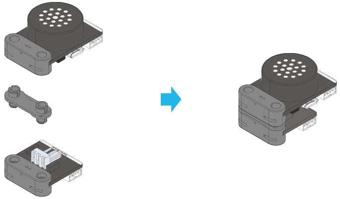
Exemple 2: Haut-parleur + une broche + une plaque coupée
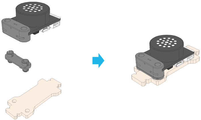
Exemple 3: Haut-parleur + une broche + une poutre (M4)
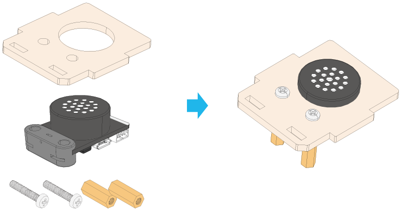
Exemple 4: Haut-parleur + une plaque coupée + deux vis + deux entretoises en laiton
Caractéristiques électroniques
Ports mBuild
La plupart des modules mBuild fournissent deux ports mBuild.
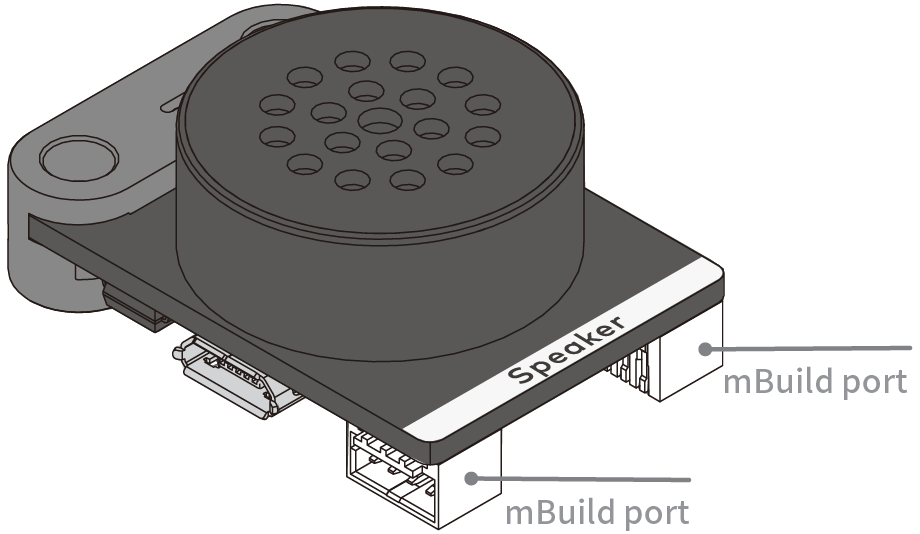
Avec les ports mBuild, plusieurs modules mBuild peuvent être connectés en série.
 De plus, l'adresse des modules peut être intelligemment identifiée lorsque vous les programmez sur mBlock 5, ce qui simplifie votre programmation. Vous n'avez pas besoin de définir les informations sur l'adresse des modules lorsque vous ajoutez ou supprimez un module.
Identification intelligente des adresses
Exemple:
Connectez CyberPi à plusieurs matrices LED
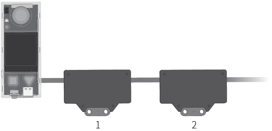 Après avoir connecté CyberPi à plusieurs matrices LED, vous devez seulement spécifier l'ordre d'une matrice LED parmi celles connectées au lieu de spécifier le port auquel la matrice LED est connectée lors de la compilation d'un programme. Comme le montre la figure précédente, la première matrice LED connectée à CyberPi est numérotée 1, la deuxième numérotée 2, et ainsi de suite.
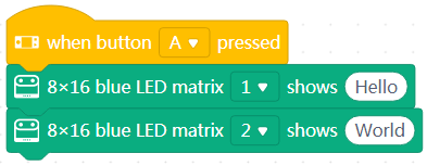 Lorsque vous appuyez sur le bouton A sur CyberPi, la première matrice LED affiche "Bonjour", et la deuxième affiche "Monde".
Changez les positions des modules, comme le montre la figure suivante.
 Le programme précédent fonctionne toujours après l'ajout d'un capteur de distance. Lorsque vous appuyez sur le bouton A sur CyberPi, la première matrice LED affiche "Bonjour", et la deuxième affiche "Monde".
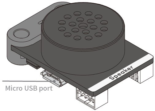
Port Micro USB
Certains modules mBuild, tels que le Haut-parleur, le Module d'alimentation et la Smart Camera, fournissent un port Micro USB, qui permet à un module de se connecter directement à un ordinateur pour l'alimentation ou la communication.
Pour savoir comment démarrer avec les modules mBuild, consultez Getting Started.
- Original: Functions and Features
Prise en main
Merci d'avoir choisi les modules mBuild !
Si vous utilisez les modules mBuild pour la première fois, lisez attentivement cette page et suivez les instructions pour ne pas manquer leurs fonctions.
Avant d'utiliser les modules mBuild
Connaître le câblage
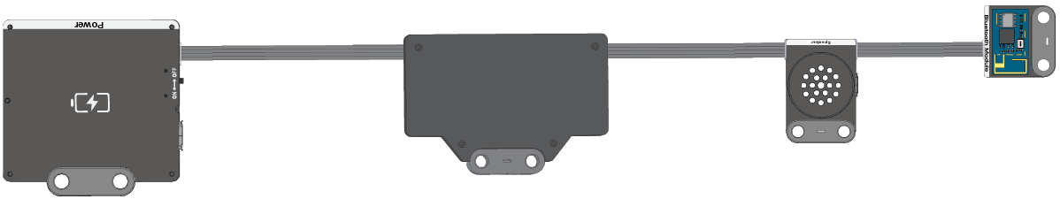
La plupart des modules mBuild fournissent deux ports mBuild et peuvent donc être connectés à des cartes de commande principales ou à d'autres modules mBuild à l'aide de câbles à 4 broches. Certains fournissent également un port Micro USB, qui permet à un module de se connecter directement à un ordinateur pour l'alimentation ou la communication. Par exemple, après avoir connecté le module haut-parleur à un ordinateur, vous pouvez stocker des fichiers audio sur celui-ci.
La figure suivante montre un câble à 4 broches.
 La figure suivante montre un exemple de connexion.
Alimenter les modules mBuild
Vous pouvez alimenter les modules mBuild de l'une des manières suivantes :
Méthode 1 : utiliser le module d'alimentation
Connectez le module d'alimentation aux autres modules à l'aide de câbles à 4 broches. Le module d'alimentation est rechargeable. Vous pouvez le recharger en le connectant à un ordinateur ou à un chargeur.
Méthode 2 : utiliser un ordinateur
Connectez les modules mBuild à une carte de commande principale, telle que Halocode ou CyberPi, à l'aide de câbles à 4 broches, puis connectez la carte de commande principale à un ordinateur.
Commencer à programmer
Avec mBlock 5, vous pouvez programmer les modules mBuild pour implémenter leurs fonctions d'entrée ou de sortie. Les modules mBuild peuvent être programmés en tant qu'appareil ou en tant que modules d'extension d'une carte de commande principale.
Obtenir mBlock 5
Sélectionnez la version applicable à votre appareil. Par exemple, si vous utilisez un PC, vous pouvez télécharger la version pour PC ou utiliser mBlock 5 sur le web.
Programmation par blocs
Programmer les modules mBuild en tant qu'appareil
Dans les étapes suivantes, mBlock 5 sur le web est utilisé.
-
Ouvrez la version web de mBlock 5 sur votre PC.
 Choisissez Fichier > Nouveau pour démarrer un nouveau projet.
-
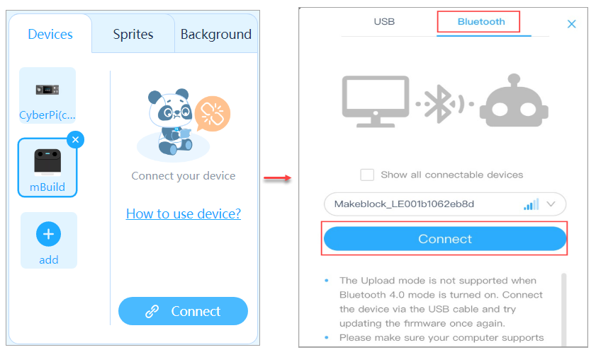
Cliquez sur + ajouter dans l'onglet Appareils et ajoutez mBuild depuis la bibliothèque d'appareils.
-
Connectez les modules mBuild à mBlock 5 via le module Bluetooth.
:::info Note : Pour programmer les modules mBuild en tant qu'appareil, vous devez les connecter à mBlock 5 via le module Bluetooth. :::
(1) Connectez les modules à programmer en série et connectez le module Bluetooth en dernier.
 (2) Allumez le module d'alimentation, activez la fonction Bluetooth de votre ordinateur, puis placez le module à proximité de l'ordinateur jusqu'à ce que l'indicateur sur le module Bluetooth reste allumé.
Note : Actuellement, la version web de mBlock 5 sur Windows ne prend pas en charge la connexion du module Bluetooth mBuild à celui-ci via le Bluetooth système. Si votre PC fonctionne sous Windows ou s'il fonctionne sous un autre système mais que le module Bluetooth ne peut pas se connecter à mBlock 5 correctement, vous pouvez utiliser le client PC mBlock 5 (mBlock V5.2.0 recommandé) ou la clé Bluetooth Makeblock. Pour plus de détails sur l'utilisation de la clé Bluetooth Makeblock, consultez la section "Connexion via la clé Bluetooth Makeblock" dans l'aide en ligne de mBlock 5.
(2) Allumez le module d'alimentation, activez la fonction Bluetooth de votre ordinateur, puis placez le module à proximité de l'ordinateur jusqu'à ce que l'indicateur sur le module Bluetooth reste allumé.
Note : Actuellement, la version web de mBlock 5 sur Windows ne prend pas en charge la connexion du module Bluetooth mBuild à celui-ci via le Bluetooth système. Si votre PC fonctionne sous Windows ou s'il fonctionne sous un autre système mais que le module Bluetooth ne peut pas se connecter à mBlock 5 correctement, vous pouvez utiliser le client PC mBlock 5 (mBlock V5.2.0 recommandé) ou la clé Bluetooth Makeblock. Pour plus de détails sur l'utilisation de la clé Bluetooth Makeblock, consultez la section "Connexion via la clé Bluetooth Makeblock" dans l'aide en ligne de mBlock 5.
(3) Cliquez sur Connecter, choisissez Bluetooth dans la boîte de dialogue qui apparaît, puis cliquez sur Connecter.
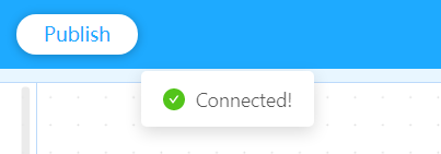
 Un message s'affiche après que les modules mBuild ont été connectés, indiquant que la connexion est réussie.
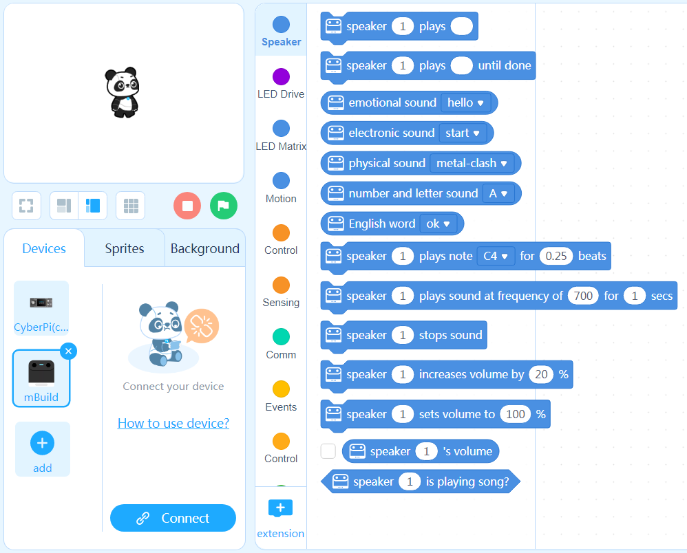
 Maintenant, vous pouvez faire glisser et déposer des blocs dans la zone de scripts pour compiler votre programme !
Programmes d'exemple
Exemple 1
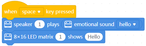 Lorsque vous appuyez sur la touche Espace, le haut-parleur dit "bonjour" et la matrice LED affiche Bonjour.
Exemple 2
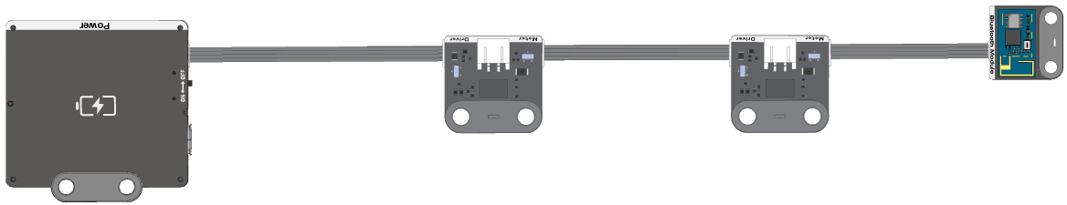
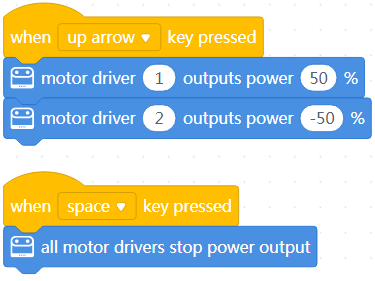 Lorsque vous appuyez sur la touche fléchée vers le haut, les deux pilotes de moteur fournissent de l'énergie ; et lorsque vous appuyez sur la touche Espace, ils cessent de fournir de l'énergie.
:::tips Conseils : Après avoir connecté les pilotes de moteur aux moteurs, vous pouvez contrôler le mouvement des moteurs par programmation. :::
Programmer les modules mBuild en tant que modules d'extension d'une carte de commande principale
Dans les étapes suivantes, Halocode est utilisé en tant que carte de commande principale.
- Cliquez sur + ajouter dans l'onglet Appareils et ajoutez Halocode depuis la bibliothèque d'appareils.
- Connectez Halocode et les modules mBuild à votre ordinateur à l'aide d'un câble Micro USB.

- Cliquez sur Connecter, puis cliquez sur Connecter dans la boîte de dialogue qui apparaît.
 Un message s'affiche après que Halocode a été connecté, indiquant que la connexion est réussie.
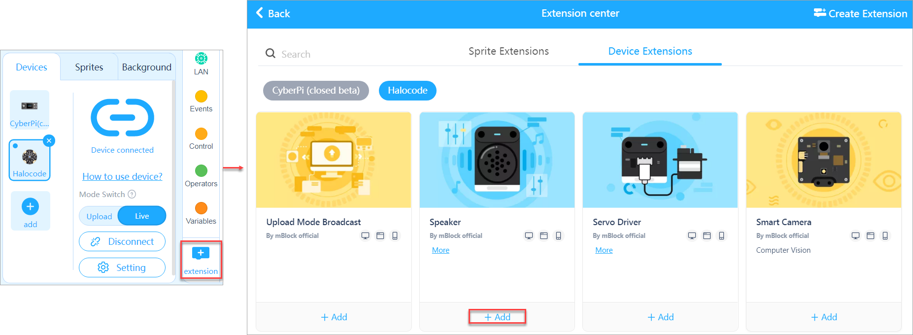
- Ajoutez les extensions Haut-parleur et Matrice LED.
(1) Ajoutez l'extension Haut-parleur.
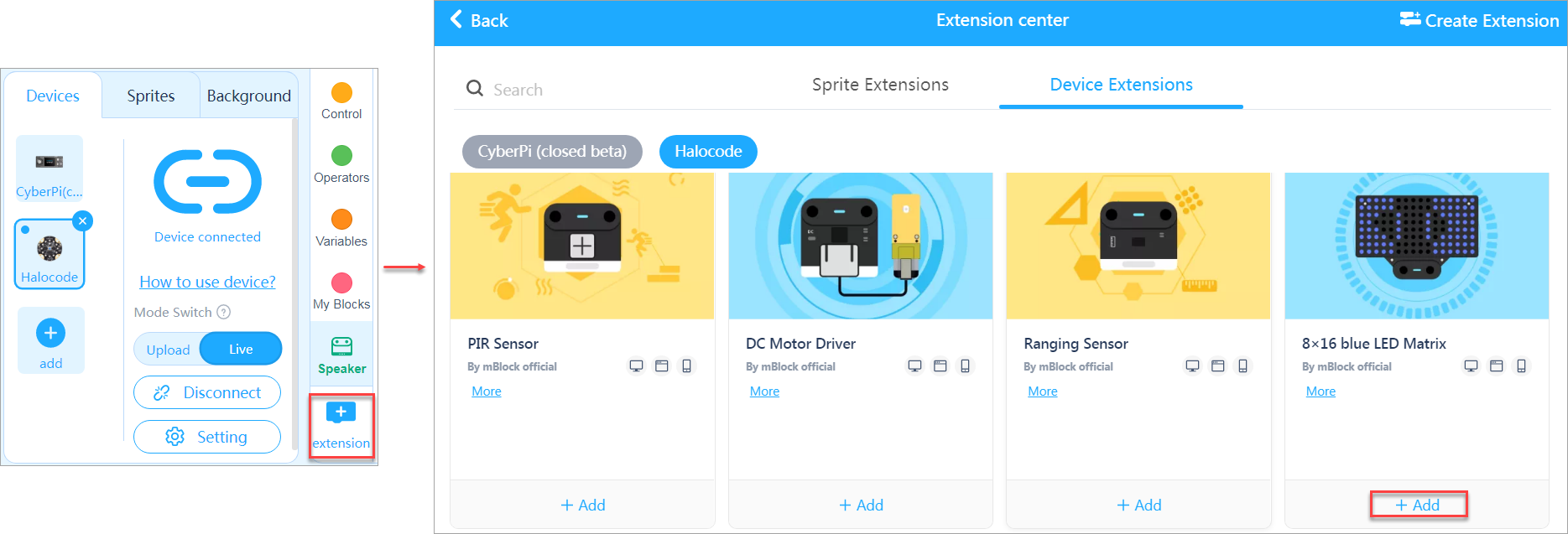 (2) Ajoutez l'extension Matrice LED.
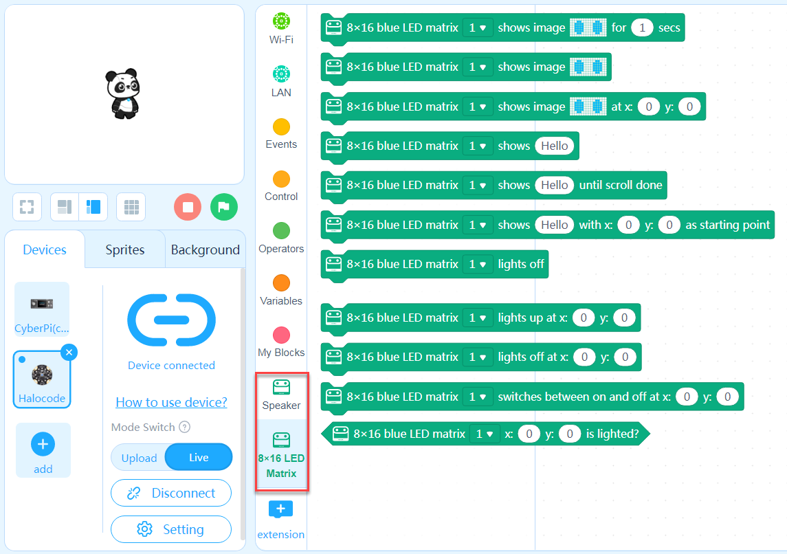
Maintenant, vous pouvez faire glisser et déposer des blocs dans la zone de scripts pour compiler votre programme !
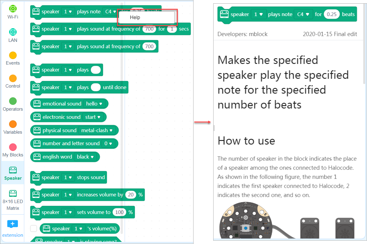
Aide sur les blocs
Si vous ne comprenez pas un bloc lors de son utilisation, vous pouvez cliquer avec le bouton droit de la souris dessus et cliquer sur Aide qui apparaît pour afficher ses informations d'aide.
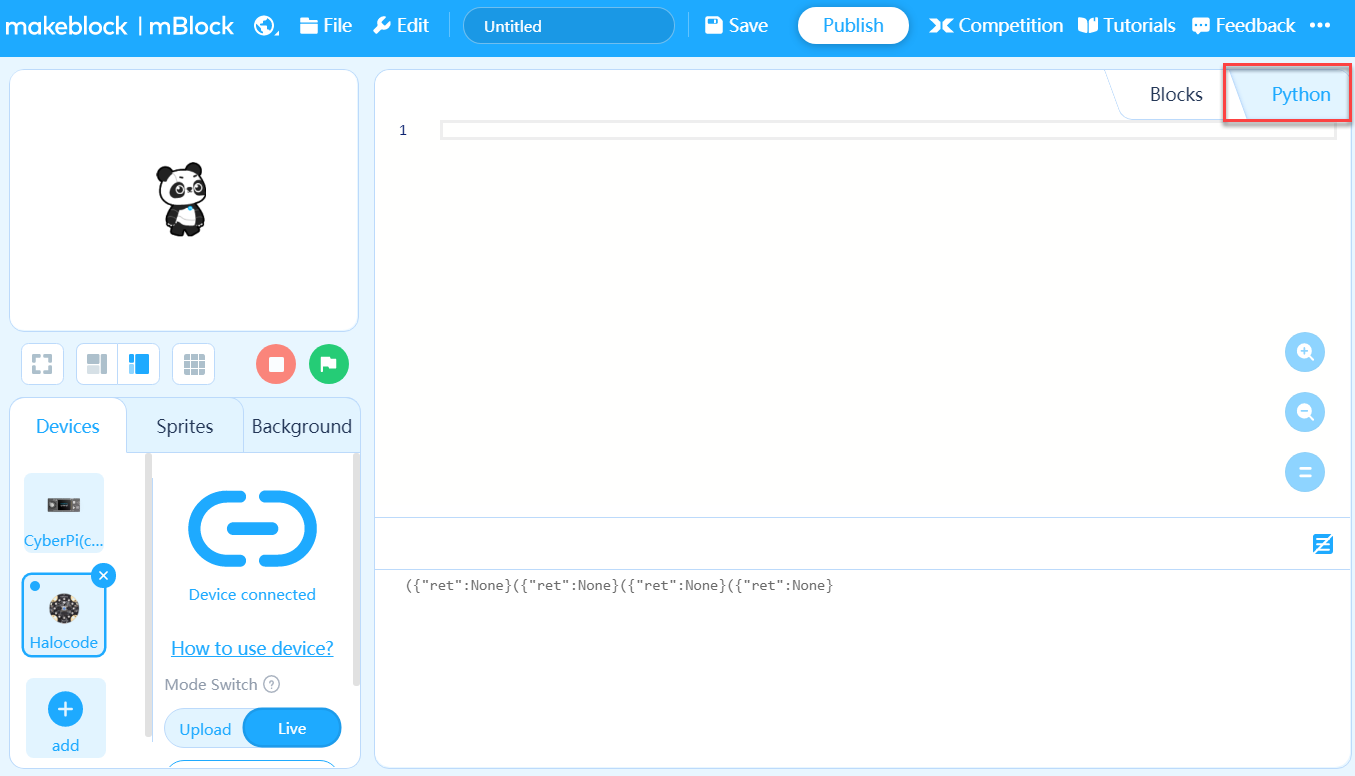
Programmation Python
Vous pouvez également utiliser MicroPython pour programmer les modules mBuild.
Réglez le langage de programmation sur Python.
Pour la documentation de l'API Python des modules mBuild, consultez API Python pour les modules mBuild.
:::tips Conseils : Vous pouvez sélectionner des modules mBuild et les monter ou les installer sur des structures fabriquées à partir de cartes découpées ou de pièces mécaniques selon les besoins. Par exemple, vous pouvez installer les modules de pilote de moteur sur une voiture fabriquée à partir de pièces mécaniques. :::
Plus d'informations
Pour les fonctions et les caractéristiques des modules mBuild, consultez Fonctions et caractéristiques.
- Texte original : https://www.yuque.com/makeblock-help-center-en/cyberpi/get-started
Alimentation
Le module d'alimentation alimente les autres modules mBuild.
Indicateurs
| Allumé | Éteint | |
|---|---|---|
| Indicateur vert | Alimentation allumée | Alimentation éteinte |
| Indicateur rouge | Faible puissance/en charge | Haute puissance/charge terminée |
Spécifications
- Dimension : 48×48mm
- Capacité de la batterie : 950mAh
- Tension de la batterie : 3,7V
- Taux de décharge : 3CC
- Durée de vie de la batterie : 3 heures (valeur de référence uniquement)
- Temps de charge : 1,25 heure
- Tension de sortie : CC 5V
- Courant de décharge : 5V 1,5A, avec une valeur instantanée maximale de 5V 2A
- Courant de protection : 5V 3A (Vous devez connecter le module d'alimentation à un chargeur pour le redémarrer après que la protection a été déclenchée.)
- Tension d'entrée : CC 5V
- Courant d'entrée : <2A
- Température de fonctionnement : 0℃–45℃
- Durée de vie : ≥ 300 cycles de batterie
Précautions
- Lisez attentivement les instructions avant de l'utiliser
- Éloignez-le des sources de chaleur, des endroits à haute tension et ne le heurtez pas ni ne le frappez pendant son utilisation
- Jetez-le correctement et en toute sécurité, et ne le jetez pas dans le feu ou l'eau
- Pendant son utilisation ou son stockage, si le module d'alimentation est chaud, fuit, sent mauvais, est déformé ou dans tout autre état anormal, arrêtez de l'utiliser immédiatement
- Texte original : https://www.yuque.com/makeblock-help-center-en/cyberpi/power
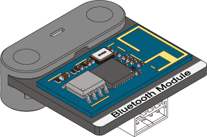
Bluetooth
Le module Bluetooth peut fonctionner avec la clé Bluetooth Makeblock ou tout appareil prenant en charge Bluetooth 4.0, vous permettant de contrôler les modules mBuild sans fil.
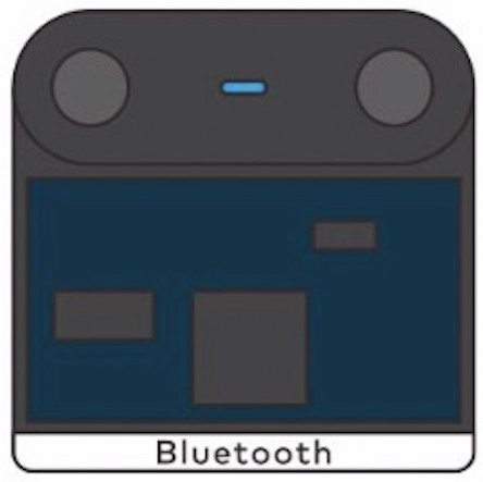
Pour les paramètres de connexion Bluetooth, voir "Connexion via Bluetooth 4.0."
Indicateur LED
- Clignotement : non connecté
- Allumé : connecté, fonctionne correctement
- Éteint : éteint ou défectueux
Spécifications
- Dimensions : 24×24 (mm)
- Distance recommandée : moins de 10 m
- Version Bluetooth : BT4.0
- Bande passante : 2402-2480 (MHz)
- Gain d'antenne : 1,5 dBi
- Niveau de consommation d'énergie : ≤4 dBm
- Courant de fonctionnement : 15 mA
- Texte original : https://www.yuque.com/makeblock-help-center-en/cyberpi/bluetooth
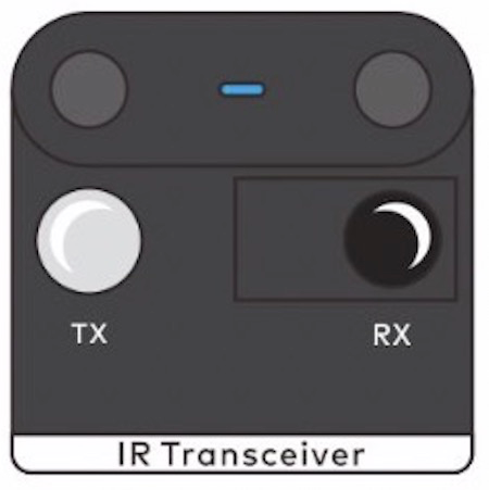
Émetteur-récepteur infrarouge
Le module émetteur-récepteur infrarouge peut transmettre et recevoir des signaux infrarouges dans la bande des 940 nm.
Exemples dans la vie réelle
- Climatiseur et sa télécommande

- Téléviseur et sa télécommande
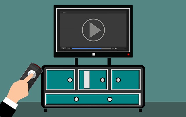
- Voiture télécommandée et sa télécommande infrarouge
Spécifications
- Dimensions : 24 × 24 (mm)
- Bande de fréquence : 940 nm
- Protocole pris en charge : NEC
- Portée de transmission : 6 m
- Portée de réception : 6 m
- Courant de fonctionnement : 40 mA
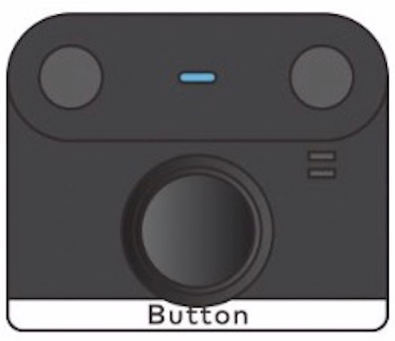
Bouton
Le module de bouton peut fonctionner comme un déclencheur d'événement, un interrupteur d'état ou un compteur.
Exemples de la vie réelle
- Le bouton d'alimentation est utilisé pour allumer ou éteindre l'ordinateur.
- Le bouton Home de l'iPhone peut être utilisé pour verrouiller ou déverrouiller l'écran.

- Les boutons d'une souris peuvent enregistrer le nombre de fois qu'ils sont pressés.

Spécifications
- Dimensions : 24 × 20 (mm)
- Durée de vie : 100 mille
- Courant de fonctionnement : 15 mA
- Texte original : https://www.yuque.com/makeblock-help-center-en/cyberpi/button
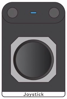
Joystick
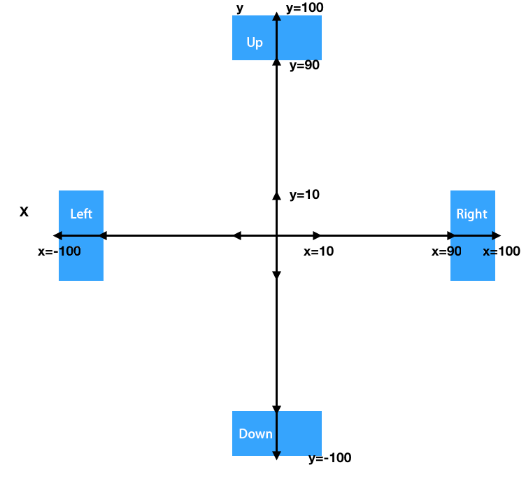
Le module joystick peut être utilisé pour contrôler la direction d'un objet en mouvement. Il peut sortir les valeurs des coordonnées x et y auxquelles il est tiré.
La figure suivante montre les plages des coordonnées et la façon dont les directions sont définies.
Exemples de la vie réelle
-
Une manette de jeu utilise des joysticks pour contrôler la direction de déplacement d'un personnage ou son champ de vision.

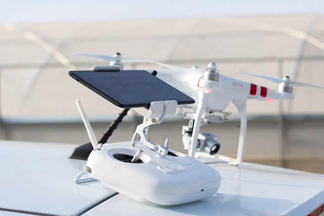
-
Une télécommande de drone utilise des joysticks pour contrôler la direction de rotation et la vitesse du drone.
Spécifications
- Dimensions : 24 × 36 (mm)
- Durée de vie : 500 mille
- Plage de valeurs de la coordonnée x : –100 à +100
- Plage de valeurs de la coordonnée y : -100 à +100
- Courant de fonctionnement : 15 mA
- Précision de réinitialisation de la position : ±0,2 mm
- Texte original : https://www.yuque.com/makeblock-help-center-en/cyberpi/joystick
Capteur d'angle
Le capteur d'angle est composé d'un encodeur magnétique qui peut détecter la position de rotation avec précision. Contrairement à la molette, le capteur d'angle peut tourner en continu, détectant les degrés de rotation et la vitesse angulaire en temps réel. De plus, le capteur d'angle peut fonctionner avec une variété de plaques pour se connecter à divers composants structuraux et ainsi être appliqué dans différents scénarios.
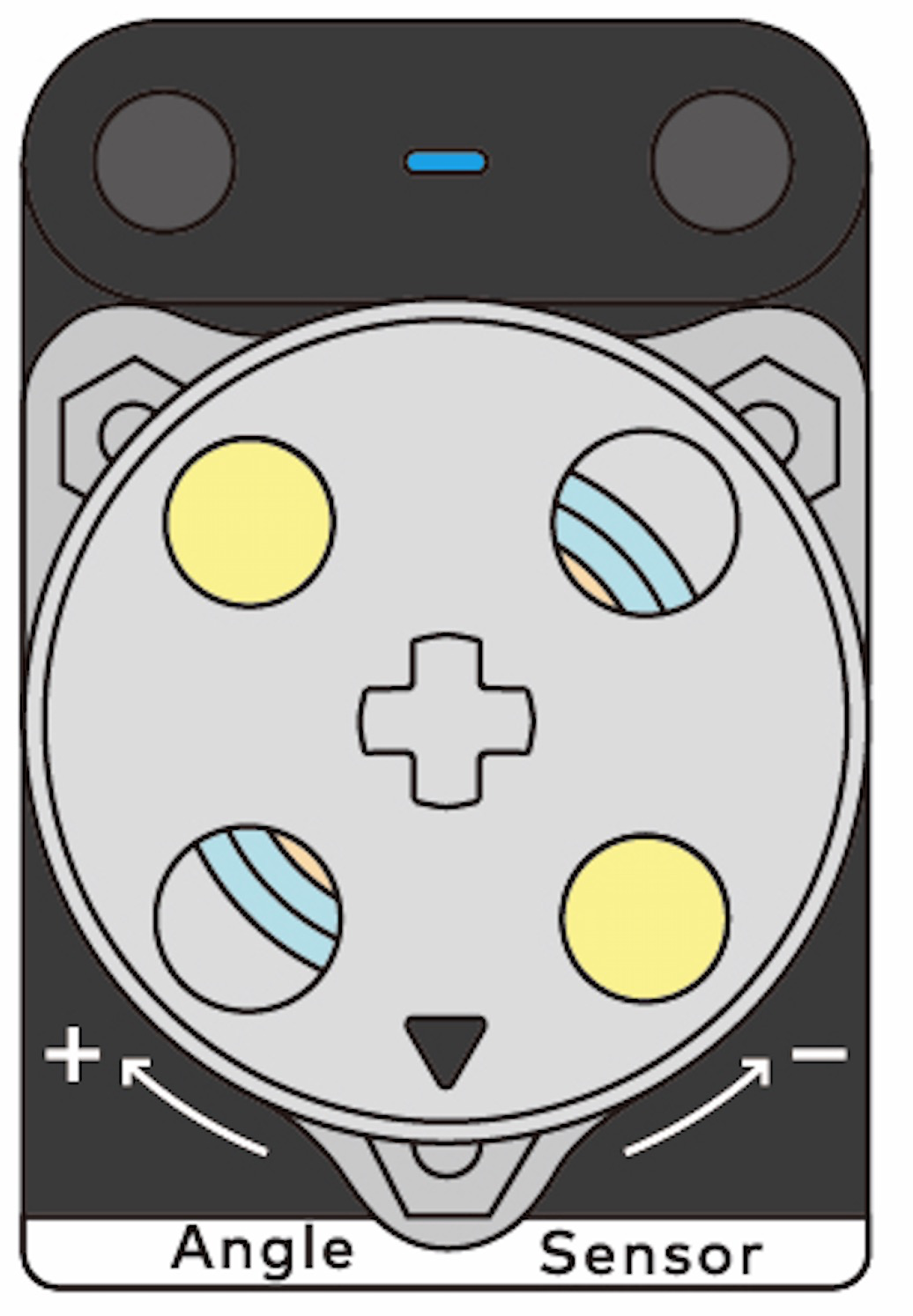
- Il peut fonctionner avec des pièces mécaniques Makeblock.
- Il peut fonctionner avec des broches Lego.
Principe de fonctionnement
Dans l'électromagnétisme, si nous appliquons une tension aux deux extrémités d'un conducteur rectangulaire, un courant est généré dans une direction. Lorsque cela se produit, si nous appliquons un champ magnétique perpendiculaire au plan du conducteur au conducteur comme indiqué dans la figure suivante, la force de Lorentz est induite, entraînant un décalage de la trajectoire des charges traversant le conducteur.
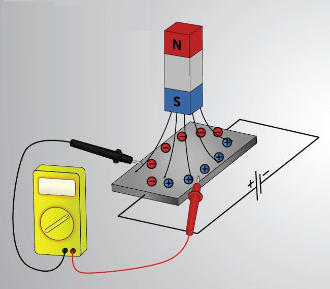
Selon la règle de la main gauche de Fleming, la direction du décalage peut être déterminée, et la direction de décalage des charges positives est opposée à celle des charges négatives. Ensuite, comme indiqué dans la figure précédente, les charges positives et négatives traversent le conducteur intermédiaire le long de deux chemins différents sur la gauche et la droite, respectivement.
Lorsque cela se produit, une différence de potentiel électrique est générée entre les côtés du conducteur, c'est-à-dire dans une direction perpendiculaire à celle dans laquelle le courant circule. C'est l'effet Hall.
Selon l'effet Hall, nous savons que le courant varie avec le changement du champ magnétique. Par conséquent, si le changement d'un champ magnétique peut être déterminé en fonction du changement de courant et ainsi le changement de position d'un aimant peut être déterminé, alors la position ou la vitesse de rotation d'un arbre équipé d'un aimant peut être détectée.
Exemples dans la vie réelle
- Certains servomoteurs intelligents utilisent des encodeurs magnétiques pour détecter les angles.
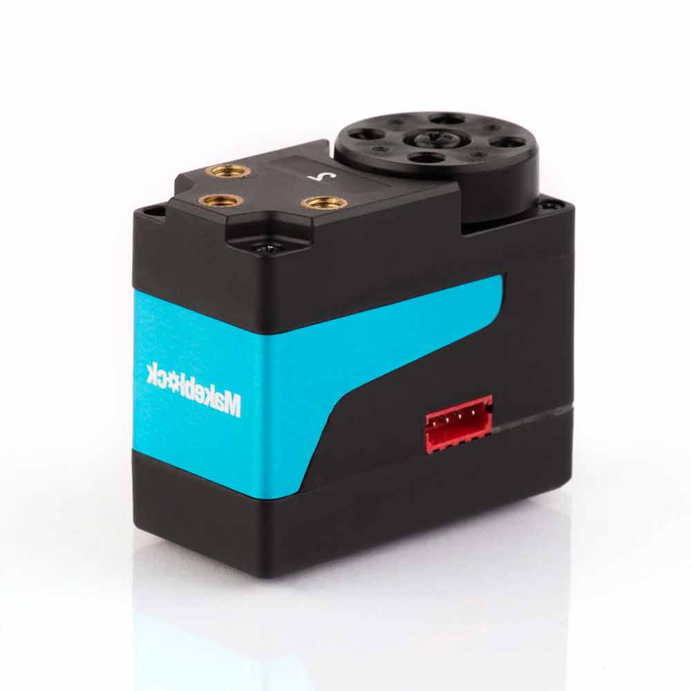
- Vous pouvez régler le volume sonore de votre Apple Watch en tournant sa Digital Crown.

Spécifications
- Dimensions : 24 × 36 (mm)
- Précision angulaire : ±1°
- Currant d'utilisation : 22 mA
Module multi-touch
Le module multi-touch est équipé de plusieurs capteurs tactiles, chacun pouvant détecter si le point de contact correspondant est touché. Lorsqu'un point de contact est touché, l'indicateur LED du capteur correspondant s'allume.
Vous pouvez également étendre les points de contact grâce à des crocodiles ou des fil conducteurs, ce qui permet d'utiliser le module multi-touch dans plus de scénarios. Par exemple, vous pouvez utiliser un fil pour connecter un point de contact à une fruits.
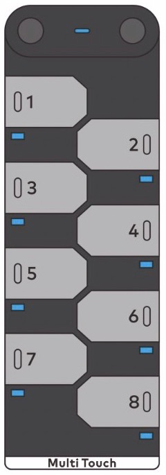
Le module multi-touch peut ajustés intelligemment les valeurs de seuil. Chaque fois que le système est mis en marche, tous les seuils sont réinitialisés. De plus, la sensibilité du module multi-touch est programmable. Par exemple, vous pouvez définir la sensibilité sur haute pour implémenter le toucher sans contact.
Fonctionnement
Le module multi-touch fonctionne selon le principe de détection de capacité. Il existe une capacité initiale (Cp) entre un point de contact et terre. Quand un point de contact est touché par vous ou par un autre conducteur, une nouvelle capacité est formée. Lorsque cela se produit, la capacité entre le point de contact et terre change, et l'MCU détermine que le point de contact est touché.
En résumant, la détection du toucher repose sur la détection de changement de capacité, et donc, l'MCU peut détecter le toucher même si aucun point de contact n'est touché.
Exemples réels
- Certains robots sont équipés de capteurs tactils sur leur dos pour détecter si ils sont touchés par les utilisateurs.

- L'écran de votre téléphone portable est un grand et complexe capteur tactile.
Spécifications
- Dimensions: 24 × 72 (mm)
- Courant d'exploitation: 18 mA
Curseur
Le module de curseur peut être utilisé pour contrôler l'entrée.
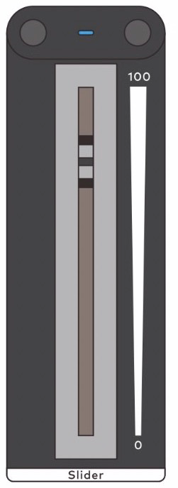
Principe de fonctionnement
Vous pouvez faire glisser le curseur sur le module de curseur pour changer la résistance et ainsi changer la tension dans le circuit correspondant. Sur la base de la relation entre la tension et la résistance, la résistance peut être calculée et ainsi la position du curseur peut être déterminée.
Exemples de la vie réelle
- Le volume sonore d'un téléphone portable est réglé à l'aide d'un curseur.
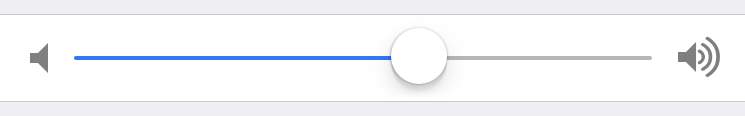
- La progression de la lecture vidéo est contrôlée à l'aide d'un curseur.

Spécifications
- Dimensions : 24 × 72 (mm)
- Durée de vie : 15 mille
- Plage de valeurs de sortie : 0–100
- Précision de la valeur : ±2%
- Courant de fonctionnement : 15 mA
- Texte original : https://www.yuque.com/makeblock-help-center-en/cyberpi/slider
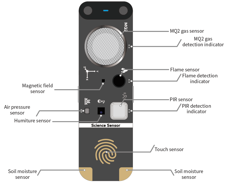
Capteur scientifique
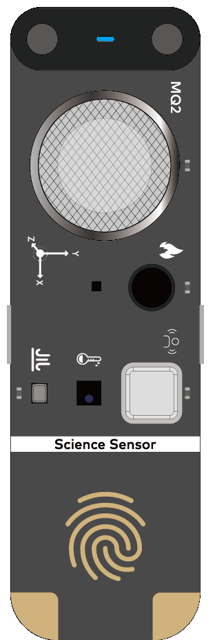
Aperçu
Le capteur scientifique est un capteur multifonction développé indépendamment par Makeblock. Intégrant les composants de détection de gaz, de champ magnétique, de flamme, de pression d'air, de température et d'humidité, de PIR, de toucher et d'humidité du sol, le capteur scientifique peut être utilisé dans divers projets de collecte de données, d'exploration scientifique et d'Internet des objets (IoT).
Fonctions et paramètres
| Ensemble | Capteur scientifique | Dimensions : 78,2 × 24 × 1,6 (mm)
Tension de fonctionnement : 5,0 V
Courant de fonctionnement : 250 mA | |
| --- | --- | --- | --- |
| Composants | Nom | Fonction | Paramètre |
| | Capteur de gaz MQ2 | Détecte de manière sensible la fumée, le gaz naturel liquéfié (GNL), le butane, le propane, le méthane, l'alcool et l'hydrogène dans l'air. | - Plage de détection de la concentration de gaz : 300-10000 ppm (gaz inflammable) - Impédance lors du chauffage : 33Ω - Consommation d'énergie de préchauffage : < 950 mW |
| | | Remarque : La déviation peut être importante au moment où le capteur est alimenté. Chauffez-le pendant cinq minutes avant de l'utiliser. | |
| | | | |
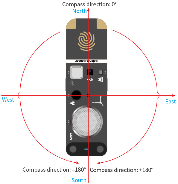
| | Capteur de champ magnétique | Mesure l'angle entre l'axe x du capteur de champ magnétique et le pôle Nord (90°N) après étalonnage. | - Plage de détection d'angle : -180° à +180° (L'angle 0° fait référence à 90°N.) - Plage de flux magnétique : ±30G (unité : gauss) |
| | | Remarque : - Placez le capteur sur un plan horizontal avant de l'utiliser. L'incliner peut entraîner une déviation de détection importante. - Assurez-vous qu'aucun matériau magnétique puissant, tel qu'un aimant, n'est placé à proximité. Sinon, des erreurs de détection peuvent se produire. | |
| | | | |
| | Capteur de flamme | Détecte une flamme et sa force par détection de lumière infrarouge. | - Plage de longueur d'onde de détection : 600-1000nm - Plage de force de flamme : 1-100 |
| | | Remarque : N'utilisez pas le capteur en plein soleil. Le soleil peut causer des interférences sévères. | |
| | | | |
| | Capteur de pression d'air | Estime l'altitude en fonction de la pression d'air détectée. | - Plage de détection de la pression de l'air : 300-1100 hPa (unité : centaines de pascals) - Plage de valeurs d'altitude : -500 m à +6000 m |
| | | Remarque : Assurez-vous qu'il n'y a pas de particules, telles que de la poussière, sur la surface du capteur. Sinon, le capteur peut être endommagé. | |
| | | | |
| | Capteur d'humiture | Détecte l'humidité et la température de l'air. | - Plage de valeurs de température : -40°C à +125°C - Erreur de température : - ±0,5°C (dans l'environnement de 0°C à 50°C) - ±1°C (dans l'environnement de -20°C à +85°C) - Plage de valeurs d'humidité : 0-100% - Erreur d'humidité : - ±3% (dans l'environnement de 50% HR) - ±5% (dans l'environnement de 20% à 80% HR) |
| | | Remarque : Assurez-vous qu'il n'y a pas de particules, telles que de la poussière, sur la surface du capteur. Sinon, la déviation de détection peut être importante ou le capteur peut ne pas fonctionner correctement. | |
| | | | |
| | Capteur PIR | Détecte si un être humain ou un animal homéotherme passe. | - Portée de détection : < 2 m - Angle de détection sur l'axe x : 80° 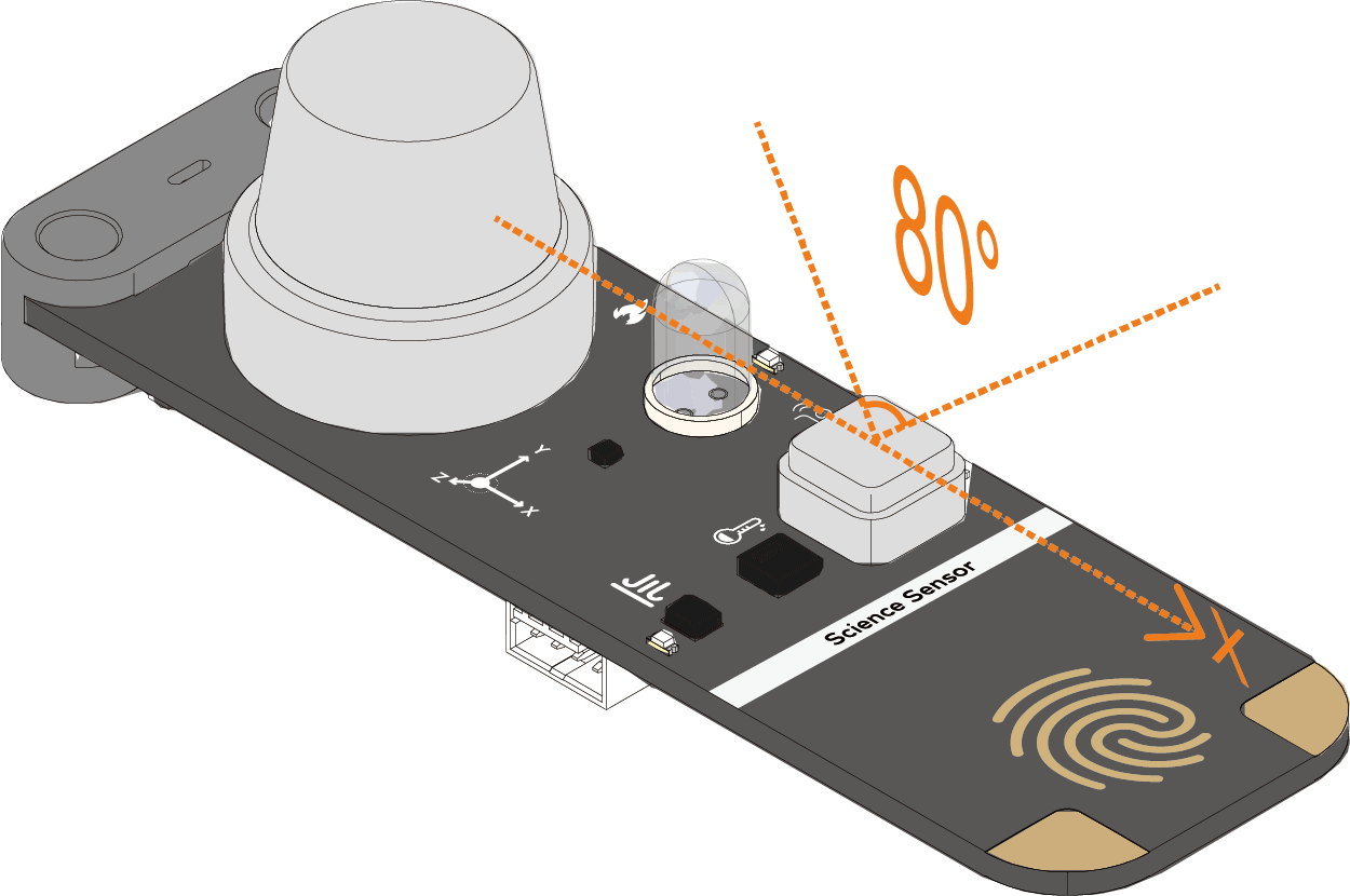 - Angle de détection sur l'axe y : 55°
 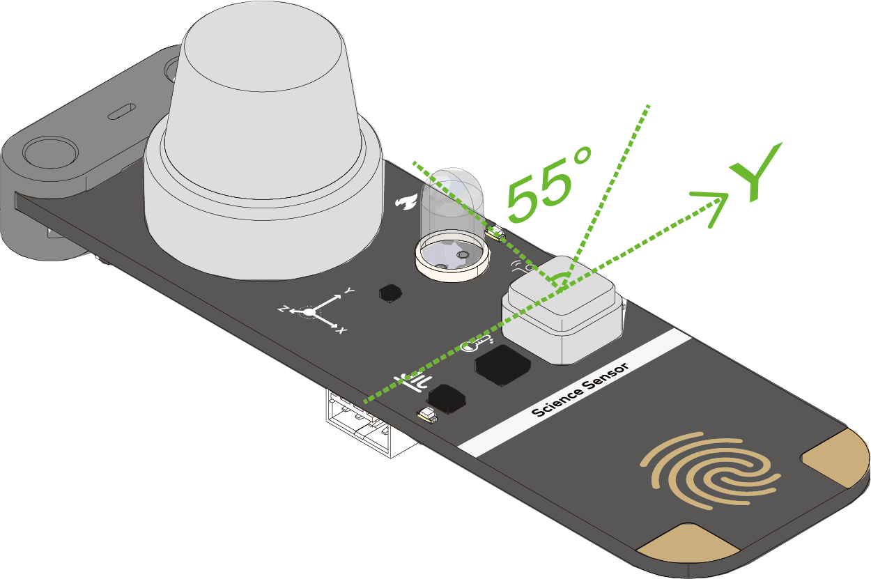 - Durée de détection après déclenchement : 2 secondes |
| | | Remarque : Ne retirez pas le filtre Fresnel blanc. Sinon, une déviation de détection importante peut être causée. | |
| | | | |
| | Capteur tactile | Détecte si une main touche le capteur. | - Zone tactile : zone avec l'empreinte digitale
- Durée de détection après déclenchement : 2 secondes |
| | | Remarque : Ne retirez pas le filtre Fresnel blanc. Sinon, une déviation de détection importante peut être causée. | |
| | | | |
| | Capteur tactile | Détecte si une main touche le capteur. | - Zone tactile : zone avec l'empreinte digitale 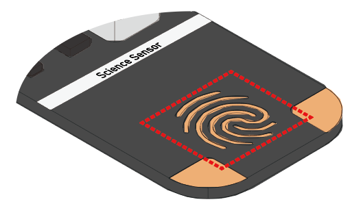 - Plage de valeurs de résistance : 0-102300000kΩ |
| | | Remarque : Gardez la zone de l'empreinte digitale claire sans aucune poussière ou goutte d'eau pour éviter les erreurs de détection. | |
| | | | |
| | Capteur d'humidité du sol | Détecte l'humidité du sol. | - Plage de détection : sondes
- Plage de valeurs de résistance : 0-102300000kΩ |
| | | Remarque : Gardez la zone de l'empreinte digitale claire sans aucune poussière ou goutte d'eau pour éviter les erreurs de détection. | |
| | | | |
| | Capteur d'humidité du sol | Détecte l'humidité du sol. | - Plage de détection : sondes 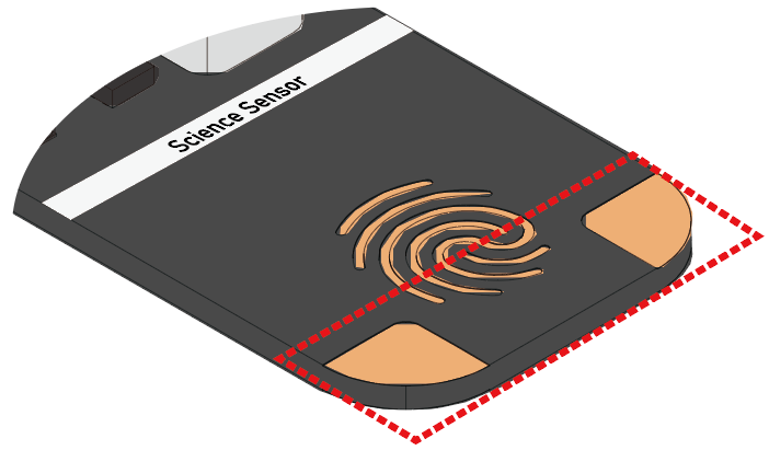 - Plage de valeurs d'humidité : 0-100% (HR) - Plage de valeurs de résistance : 0-102200kΩ |
| | | Remarque : Assurez-vous que la plaque signalétique du capteur scientifique est maintenue au-dessus du sol lorsque vous insérez le capteur dans le sol. Sinon, les autres composants de détection peuvent être endommagés. | |
- Plage de valeurs d'humidité : 0-100% (HR) - Plage de valeurs de résistance : 0-102200kΩ |
| | | Remarque : Assurez-vous que la plaque signalétique du capteur scientifique est maintenue au-dessus du sol lorsque vous insérez le capteur dans le sol. Sinon, les autres composants de détection peuvent être endommagés. | |
Programmes d'exemple
Programmes d'exemple pour le capteur scientifique
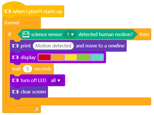
Exemple 1 : Lampe sensible au PIR (utilisation du capteur PIR)
Vous pouvez contrôler les LED sur CyberPi en fonction du capteur PIR et afficher le résultat de détection du capteur PIR sur l'écran. Pour le principe de fonctionnement du capteur PIR, voir le Principe de fonctionnement du capteur PIR.
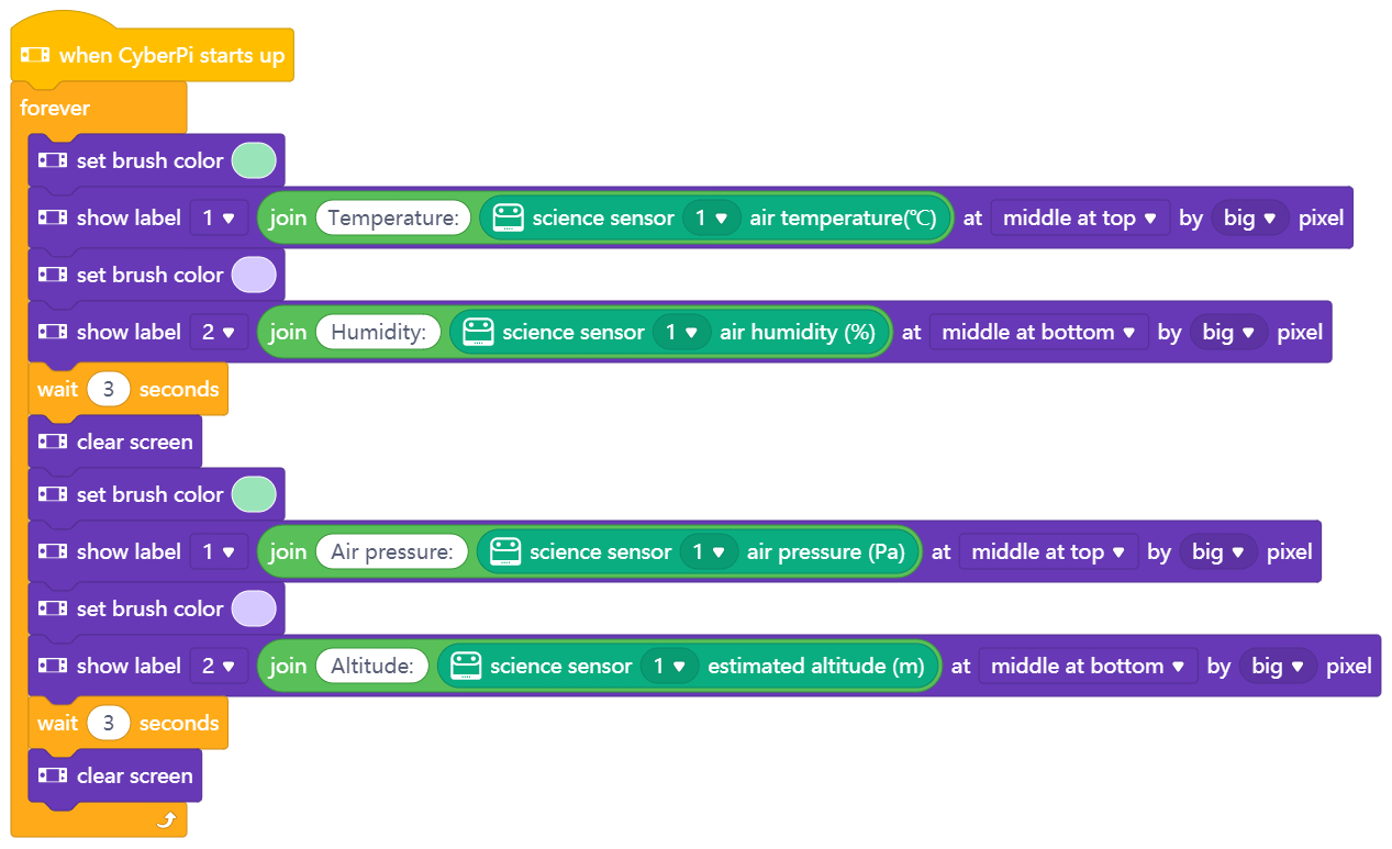
Exemple 2 : Détecteur d'environnement (utilisation du capteur d'humiture et du capteur de pression d'air)
Le capteur d'humiture sur le capteur scientifique peut être utilisé pour détecter la température et l'humidité ambiantes, et le capteur de pression d'air peut être utilisé pour détecter la pression de l'air et estimer l'altitude. Vous pouvez programmer l'écran de CyberPi pour afficher toutes les données de sortie des capteurs.
Exemple 3 : Alarme incendie (utilisation du capteur de gaz MQ2 et du capteur de flamme)
Le capteur scientifique intègre un capteur de gaz MQ2 et un capteur de flamme, qui peuvent être utilisés pour détecter les fuites de gaz et les incendies dans les foyers. Avec ces deux capteurs, vous pouvez réaliser une alarme simple qui doit être déclenchée par un gaz inflammable ou une flamme. Lorsque l'alarme est déclenchée, CyberPi émet un son d'avertissement.
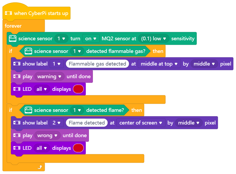
Pour le principe de fonctionnement du capteur de flamme, voir le Principe de fonctionnement du capteur de flamme. Le capteur de flamme est déclenché par le rayonnement infrarouge, et le rayonnement infrarouge émis par un corps humain peut également le déclencher. Par conséquent, dans la pratique, vous pouvez définir un seuil (force de la flamme détectée) pour déclencher le capteur de flamme.

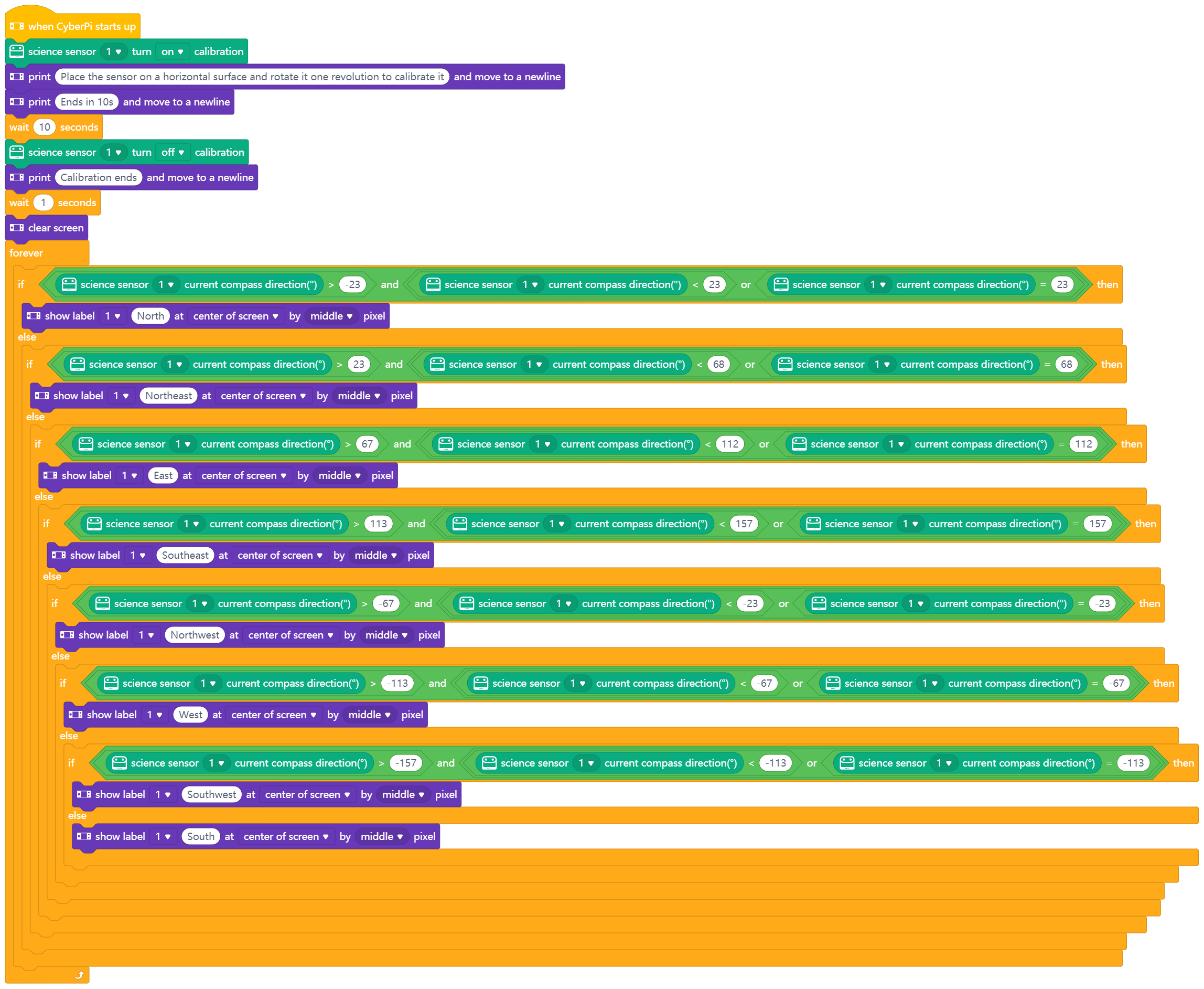
Exemple 4 : Boussole (utilisation du capteur de champ magnétique)
Le capteur de champ magnétique sur le capteur scientifique peut être utilisé pour fonctionner comme une boussole. La déclinaison magnétique varie en fonction de la région, et donc vous devez étalonner le capteur de champ magnétique avant de l'utiliser.
:::info
Remarque : Vous devez étalonner le capteur de champ magnétique dans un environnement non magnétique. Un espace extérieur ouvert est recommandé.
:::
Utilisez le bloc suivant pour activer ou désactiver l'étalonnage.
 Plage de valeurs de sortie : -180° à +180° (où 0° indique que le capteur scientifique pointe vers 90°N, le pôle Nord)
Programmez le capteur scientifique pour qu'il fonctionne comme une boussole.
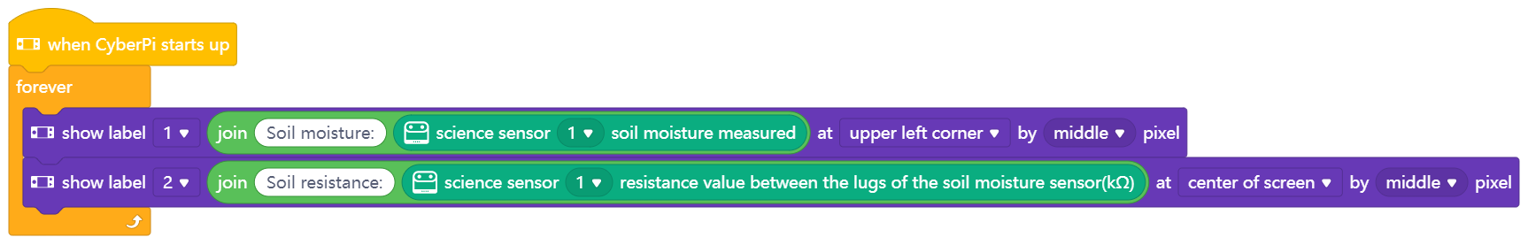
Exemple 5 : Détecteur d'humidité du sol (utilisation du capteur d'humidité du sol)
Le capteur d'humidité du sol sur le capteur scientifique est de type résistif. Lorsque l'humidité du sol augmente, l'eau peut dissoudre les ions contenus dans une partie du sol, de sorte que la résistance du sol diminue et que la valeur de sortie du capteur d'humidité du sol devient plus grande. Lorsque la teneur en eau dans le sol augmente encore (dans les cas extrêmes, imaginez que vous jetez du sol dans l'eau), la concentration en ions dans le sol est diluée par l'excès d'eau, ce qui entraîne une diminution de la conductivité électrique et une augmentation de la résistance. C'est pourquoi vous pouvez constater que le capteur d'humidité du sol produit une valeur plus faible dans l'eau pure que dans le sol humide (bien que l'ancien ait une teneur en eau significativement plus élevée) car la concentration en ions dans le sol humide est plus élevée et la résistance est plus faible.
Avec le programme suivant, vous pouvez afficher le changement d'humidité et de résistance du sol détecté par le capteur d'humidité du sol.
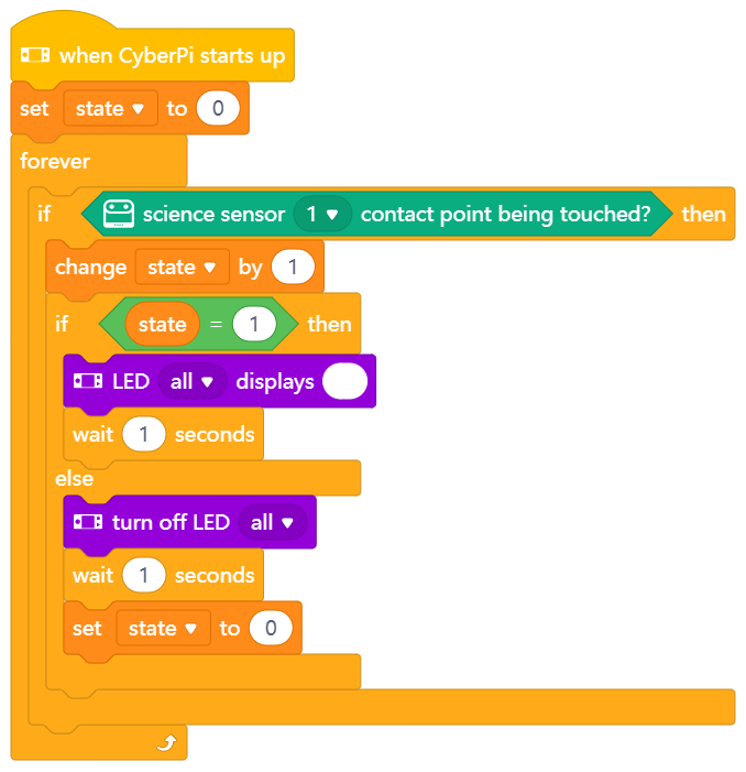
Exemple 6 : Lampe à commande tactile (utilisation du capteur tactile)
Le capteur tactile sur le capteur scientifique peut détecter si le point de contact est touché et peut donc implémenter un contrôle basé sur le toucher. Avec le programme suivant, vous pouvez contrôler les LED sur CyberPi en touchant le capteur tactile.
Capteur RGB quadruple
Le capteur RGB quadruple utilise la lumière visible comme source de remplissage, ce qui réduit considérablement les interférences de la lumière ambiante. De plus, il offre la fonction de reconnaissance des couleurs. La nouvelle fonction de calibration de la lumière ambiante réduit également les interférences de la lumière ambiante lors du suivi de ligne. Avec quatre capteurs de lumière, il peut prendre en charge plus de scénarios de programmation.

| Capteur RGB quadruple | Capteur de couleur RGB double | |
|---|---|---|
| Boîtier en plastique pour améliorer la durabilité et la qualité | Oui | Non |
| Capteur de suivi de ligne | 4 | 2 |
| Capteur de couleur | 4 | |
| (qui servent également de capteurs de suivi de ligne) | Non | |
| Capteur de lumière | 4 | |
| (qui servent également de capteurs de suivi de ligne) | Non | |
| Lumière de remplissage | Lumière visible | Lumière infrarouge |
| Calibration de la lumière ambiante pour réduire significativement les interférences de la lumière ambiante | Oui | Non |
Spécifications
Plage de détection : 5–15 mm de l'objet à détecter
Description du bouton
- Double pression : Lorsque le bouton est pressé deux fois, le capteur RGB quadruple commence à apprendre l'arrière-plan et la ligne pour le suivi de ligne.
Placez les capteurs de lumière sur l'arrière-plan de la carte de suivi de ligne et appuyez deux fois sur le bouton. Lorsque vous voyez les LEDs indiquer l'état de suivi de ligne clignoter rapidement, balancez les capteurs de gauche à droite au-dessus de l'arrière-plan et de la ligne jusqu'à ce que les LEDs arrêtent de clignoter. Cela prend environ 2,5 secondes. Les valeurs des paramètres obtenues sont automatiquement stockées. Si l'apprentissage échoue, les LEDs clignotent lentement, et vous devez recommencer l'apprentissage.
- Appui long : Lorsque le bouton est pressé longuement, le capteur RGB quadruple change la couleur des lumières de remplissage. En général, vous n'avez pas besoin de changer la couleur. La couleur est définie automatiquement après que l'apprentissage est terminé.
Guide de programmation
Vous pouvez utiliser mBlock 5 pour programmer le capteur RGB quadruple. Connectez le capteur RGB quadruple à CyberPi, ajoutez CyberPi et connectez-le à mBlock 5, puis ajoutez l'extension Quad RGB Sensor. Pour plus de détails sur la façon d'ajouter CyberPi et de le connecter à mBlock 5 et sur la façon d'ajouter l'extension, voir "Ajouter et connecter mBot2" et "Ajouter des extensions."
Définir le mode de détection
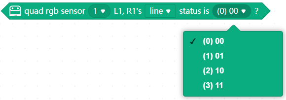
Le capteur RGB quadruple peut être programmé pour détecter l'une des deux options suivantes :
- couleur
- niveaux de gris
Pour la détection des couleurs, le capteur RGB quadruple mesure la lumière réfléchie par un objet en termes de ses valeurs Rouge, Vert et Bleu (RVB). Huit couleurs sont disponibles.
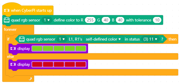
Pour détecter une couleur, vous devez sélectionner une couleur dans le bloc à utiliser, par exemple :
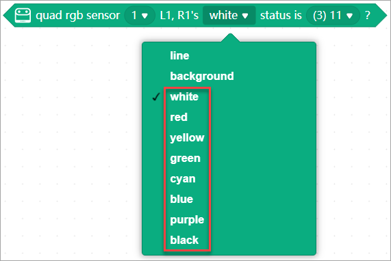
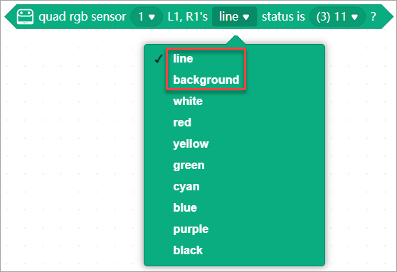
Pour la détection des niveaux de gris, le capteur RGB quadruple mesure l'intensité de la lumière réfléchie par un objet indépendamment de sa couleur.
Pour détecter le niveau de gris, vous devez sélectionner ligne ou arrière-plan dans le bloc à utiliser, par exemple :
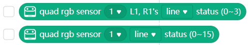
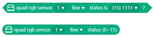
Obtenir les valeurs de sortie
Le capteur RGB quadruple peut produire des valeurs basées sur la couleur ou le niveau de gris qu'il détecte, et vous pouvez obtenir ces valeurs en utilisant les blocs reporters, par exemple :
Changer la couleur des lumières de remplissage
Vous pouvez changer la couleur des lumières de remplissage entre vert, rouge et bleu en appuyant longuement sur le bouton ou en utilisant le bloc suivant :
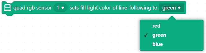
:::info Remarque : Le capteur RGB quadruple peut détecter les couleurs indépendamment des couleurs des lumières de remplissage. :::
Vous devez changer la couleur des lumières de remplissage dans certains scénarios d'application. Pour plus de détails, voir "Scénarios de détection de ligne."
Scénarios de détection de ligne
Avant d'utiliser le capteur RGB quadruple pour détecter des lignes, vous devez effectuer une calibration de base sur celui-ci.
Calibration de base
- Placez les quatre capteurs de lumière du capteur RGB quadruple sur l'arrière-plan et appuyez deux fois sur le bouton du capteur, puis balancez le capteur horizontalement sur la ligne et l'arrière-plan.
- Vérifiez les deux capteurs de lumière au milieu (L1 et R1) du capteur RGB quadruple. Si le robot est sur la ligne, les LEDs bleues des deux capteurs de lumière doivent être éteintes. Les deux LEDs s'allument et s'éteignent alternativement lorsque vous balancez le robot sur la ligne. :::tips Conseils : Le capteur RGB quadruple peut détecter les lignes sombres sur des arrière-plans clairs indépendamment de la couleur de l'éclairage. :::
Les scénarios de détection de ligne suivants décrivent plusieurs scénarios, et les objectifs et blocs recommandés pour chaque scénario.
Scénario 1 : Ligne noire + marge blanche autour de la ligne + fond blanc
Par exemple :
 Effectuez une calibration de base sur le capteur RGB quadruple, afin qu'il puisse reconnaître la ligne et l'arrière-plan.
| Niveau | Objectif(s) et bloc(s) recommandé(s) | Remarques |
|---|---|---|
| 1a: débutant |
- Pour déterminer si le capteur RGB quadruple détecte l'état spécifique de la ligne :
- Pour obtenir l'état de la ligne détectée
 |
|
| 1b: intermédiaire |
|
|
| 1b: intermédiaire |  Pour détecter les croisements
 | Le capteur RGB quadruple ne peut pas ignorer la ligne, et donc il ne peut pas déterminer si une intersection est réellement un croisement ("+" forme, la ligne réelle continue après la T). Ceci peut seulement être vérifié en roulant droit sur la T et en détectant si la ligne continue. |
| 1c: avancé | Pour mettre en œuvre un suivi de ligne fluide :
| Le capteur RGB quadruple ne peut pas ignorer la ligne, et donc il ne peut pas déterminer si une intersection est réellement un croisement ("+" forme, la ligne réelle continue après la T). Ceci peut seulement être vérifié en roulant droit sur la T et en détectant si la ligne continue. |
| 1c: avancé | Pour mettre en œuvre un suivi de ligne fluide :
 | Vérifiez la valeur de sortie de ce bloc.
Changez la couleur des lumières de remplissage pour vous assurer que la valeur de sortie est 0 lorsque le robot est au milieu de la ligne.
La couleur de la lumière de remplissage peut avoir un léger impact sur la valeur de sortie. |
| Vérifiez la valeur de sortie de ce bloc.
Changez la couleur des lumières de remplissage pour vous assurer que la valeur de sortie est 0 lorsque le robot est au milieu de la ligne.
La couleur de la lumière de remplissage peut avoir un léger impact sur la valeur de sortie. |
Scénario 2 : Ligne noire avec des sections colorées + marge blanche autour de la ligne + fond blanc
Par exemple :
 Les objectifs et blocs recommandés sont les mêmes que ceux du Scénario 1, mais une calibration spéciale est nécessaire.
L'une des méthodes suivantes peut être utilisée :
Les objectifs et blocs recommandés sont les mêmes que ceux du Scénario 1, mais une calibration spéciale est nécessaire.
L'une des méthodes suivantes peut être utilisée :
-
Effectuez la calibration de base sur la couleur la plus claire parmi les sections colorées, par exemple, jaune, de sorte que toutes les couleurs plus sombres soient reconnues comme noires.
-
Effectuez une calibration de base sur la ligne noire, puis appuyez longuement sur le bouton du capteur pour changer la couleur des lumières de remplissage et voir si le capteur reconnaît les différentes sections colorées comme la ligne à suivre.
- section rouge : utilisez les lumières de remplissage vertes ou bleues/blanches
- section jaune : utilisez les lumières de remplissage bleues/blanches
- sections verte et bleue : toutes les lumières de remplissage fonctionnent :::warning Important à savoir :
-
Si vous avez défini la couleur des lumières de remplissage sur mBlock 5, la calibration réinitialise les lumières de remplissage (chaque lumière de remplissage passe rapidement par l'illumination R/G/B).
-
Les sections colorées à l'intérieur de la ligne à suivre peuvent affecter le suivi de ligne avancé et fluide (reconnu comme l'écart par rapport à la ligne). Par exemple, lorsque la calibration de base est effectuée sur la section jaune, la section bleue peut être signalée comme un écart même si elle est à 100% sur la ligne. :::
Scénario 3 : Ligne monocolore + marge blanche autour de la ligne + fond blanc
Par exemple :
 Effectuez une calibration de base sur le capteur RGB quadruple, afin qu'il puisse reconnaître la ligne et l'arrière-plan.
Les objectifs et blocs recommandés sont les mêmes que ceux du Scénario 1.
:::info
Remarques :
Effectuez une calibration de base sur le capteur RGB quadruple, afin qu'il puisse reconnaître la ligne et l'arrière-plan.
Les objectifs et blocs recommandés sont les mêmes que ceux du Scénario 1.
:::info
Remarques :
- Si vous utilisez le bloc de reporting de l'écart, appuyez longuement sur le bouton du capteur RGB quadruple pour changer la couleur des lumières de remplissage pour vous assurer que la valeur de sortie est 0 lorsque vous placez le robot au milieu de la ligne.
- Il n'est pas recommandé d'utiliser le bloc de reporting de l'écart lorsque le contraste entre la ligne et l'arrière-plan est faible. :::
Scénario 4 : Ligne noire + marge blanche autour de la ligne + fond coloré/illustrations
Par exemple :
 Effectuez une calibration de base sur le capteur RGB quadruple, afin qu'il puisse reconnaître la ligne et l'arrière-plan.
| Niveau | Objectif(s) et bloc(s) recommandé(s) | Remarques |
|---|---|---|
| 4a: débutant |
- Pour déterminer si le capteur RGB quadruple détecte l'état spécifique de la ligne :

- Pour obtenir l'état de la ligne détectée
 |
|
| 4b: intermédiaire |
|
|
| 4b: intermédiaire | 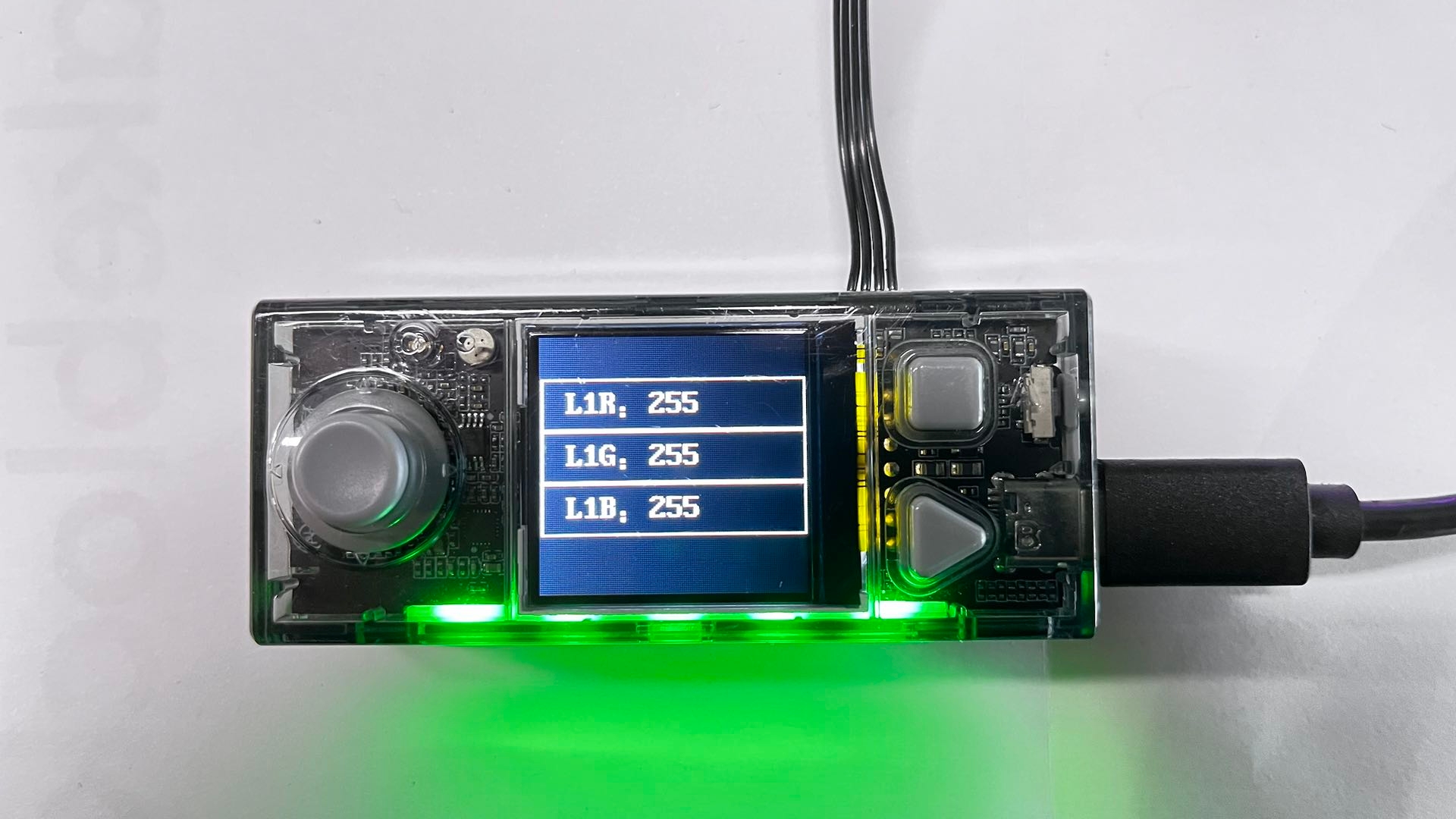 Pour détecter les croisements :
 | Les zones extérieures (arrière-plan) peuvent être reconnues comme la ligne à suivre, en fonction des conditions d'éclairage.
Lorsque cela se produit, vous pouvez utiliser uniquement les capteurs de lumière L1 et R1 pour détecter les lignes, ou vous assurer que la marge blanche autour de la ligne est suffisamment large pour empêcher les capteurs de détecter l'arrière-plan extérieur. |
| 4c: avancé | Pour détecter l'écart par rapport à la ligne :
 | Si les couleurs des zones extérieures sont suffisamment proches de la couleur de la ligne à suivre, la valeur de sortie du bloc de reporting de l'écart peut être affectée, et la détection de l'écart peut ne pas être fiable. |
Scénario 5 : Ligne noire + marge blanche autour de la ligne + fond réfléchissant
Par exemple :
 Effectuez une calibration de base sur le capteur RGB quadruple, afin qu'il puisse reconnaître la ligne et l'arrière-plan.
Les objectifs et blocs recommandés sont les mêmes que ceux du Scénario 1.
:::info
Remarques :
Effectuez une calibration de base sur le capteur RGB quadruple, afin qu'il puisse reconnaître la ligne et l'arrière-plan.
Les objectifs et blocs recommandés sont les mêmes que ceux du Scénario 1.
:::info
Remarques :
- L'arrière-plan réfléchissant peut refléter la lumière, ce qui peut affecter la détection de la ligne. Lorsque cela se produit, utilisez une bande de ruban adhésif noire sur les zones réfléchissantes pour améliorer la détection de la ligne.
- Si la ligne n'est pas reconnue, vérifiez si elle est trop réfléchissante et utilisez une bande de ruban adhésif noire pour améliorer la détection de la ligne. :::
Scénario 6 : Ligne noire + marge noire autour de la ligne + fond blanc
Par exemple :
 Effectuez une calibration de base sur le capteur RGB quadruple, afin qu'il puisse reconnaître la ligne et l'arrière-plan.
| Niveau | Objectif(s) et bloc(s) recommandé(s) | Remarques |
|---|---|---|
| 6a: débutant |
- Pour déterminer si le capteur RGB quadruple détecte l'état spécifique de la ligne :

- Pour obtenir l'état de la ligne détectée
 |
|
| 6b: intermédiaire |
|
|
| 6b: intermédiaire |  Pour détecter les croisements :
| Les zones extérieures (arrière-plan) peuvent être reconnues comme la ligne à suivre, en fonction des conditions d'éclairage.
Pour détecter les croisements :
| Les zones extérieures (arrière-plan) peuvent être reconnues comme la ligne à suivre, en fonction des conditions d'éclairage.
Lorsque cela se produit, vous pouvez utiliser uniquement les capteurs de lumière L1 et R1 pour détecter les lignes, ou vous assurer que la marge blanche autour de la ligne est suffisamment large pour empêcher les capteurs de détecter l'arrière-plan extérieur. |
| 6c: avancé | Pour détecter l'écart par rapport à la ligne :
| Si les couleurs des zones extérieures sont suffisamment proches de la couleur de la ligne à suivre, la valeur de sortie du bloc de reporting de l'écart peut être affectée, et la détection de l'écart peut ne pas être fiable. |
Scénario 7 : Ligne noire + marge blanche autour de la ligne + fond réfléchissant + variations de luminosité
Par exemple :
 Effectuez une calibration de base sur le capteur RGB quadruple, afin qu'il puisse reconnaître la ligne et l'arrière-plan.
| Niveau | Objectif(s) et bloc(s) recommandé(s) | Remarques |
|---|---|---|
| 7a: débutant |
- Pour déterminer si le capteur RGB quadruple détecte l'état spécifique de la ligne :

- Pour obtenir l'état de la ligne détectée
 |
|
| 7b: intermédiaire |
Pour détecter les croisements :
| Les zones extérieures (arrière-plan) peuvent être reconnues comme la ligne à suivre, en fonction des conditions d'éclairage.
|
|
| 7b: intermédiaire |
Pour détecter les croisements :
| Les zones extérieures (arrière-plan) peuvent être reconnues comme la ligne à suivre, en fonction des conditions d'éclairage.
Lorsque cela se produit, vous pouvez utiliser uniquement les capteurs de lumière L1 et R1 pour détecter les lignes, ou vous assurer que la marge blanche autour de la ligne est suffisamment large pour empêcher les capteurs de détecter l'arrière-plan extérieur. |
| 7c: avancé | Pour détecter l'écart par rapport à la ligne :
| Si les couleurs des zones extérieures sont suffisamment proches de la couleur de la ligne à suivre, la valeur de sortie du bloc de reporting de l'écart peut être affectée, et la détection de l'écart peut ne pas être fiable. |
Scénario 8 : Ligne monocolore + marge blanche autour de la ligne + fond coloré + variations de luminosité
Par exemple :
 Effectuez une calibration de base sur le capteur RGB quadruple, afin qu'il puisse reconnaître la ligne et l'arrière-plan.
Les objectifs et blocs recommandés sont les mêmes que ceux du Scénario 1.
:::info
Remarques :
Effectuez une calibration de base sur le capteur RGB quadruple, afin qu'il puisse reconnaître la ligne et l'arrière-plan.
Les objectifs et blocs recommandés sont les mêmes que ceux du Scénario 1.
:::info
Remarques :
- L'arrière-plan coloré et les variations de luminosité peuvent affecter la détection de la ligne. Lorsque cela se produit, vérifiez si la couleur de l'éclairage de remplissage est uniforme et si la couleur de la ligne à suivre est suffisamment contrastée par rapport à l'arrière-plan.
- Si la ligne n'est pas reconnue, essayez de changer la couleur des lumières de remplissage et répétez le processus de calibration de base. :::
FAQ
Pourquoi les lumières de remplissage clignotent-elles rapidement sur un mélange de couleurs ?
Lorsque les lumières de remplissage passent rapidement par l'illumination R/G/B, cela signifie que les lumières de remplissage sont réinitialisées. Cela se produit lorsque vous effectuez une calibration de base, et lorsque vous définissez la couleur des lumières de remplissage sur mBlock 5, ce qui peut affecter les valeurs de sortie du capteur RGB quadruple.
Pourquoi le capteur RGB quadruple ne détecte-t-il pas la ligne ?
Si le capteur RGB quadruple ne détecte pas la ligne, vérifiez les points suivants :
- Vérifiez si la ligne est suffisamment contrastée par rapport à l'arrière-plan, et essayez de modifier la couleur des lumières de remplissage.
- Vérifiez si la ligne est trop réfléchissante ou trop sombre. Si c'est le cas, utilisez une bande de ruban adhésif noire sur la ligne réfléchissante pour améliorer la détection de la ligne.
- Vérifiez si la couleur de la lumière de remplissage affecte la valeur de sortie du capteur RGB quadruple.
- Assurez-vous que le capteur RGB quadruple est placé au-dessus de la ligne de manière équilibrée. Si ce n'est pas le cas, il peut ne pas être capable de détecter la ligne.
- Si la ligne est fine ou s'il y a des variations de luminosité dans l'environnement, cela peut affecter la détection de la ligne.
Pourquoi le capteur RGB quadruple détecte-t-il l'arrière-plan extérieur comme la ligne ?
Lorsque l'arrière-plan extérieur est reconnu comme la ligne à suivre, vérifiez les points suivants :
- Vérifiez si la marge blanche autour de la ligne est suffisamment large pour empêcher les capteurs de détecter l'arrière-plan extérieur.
- Vérifiez si les zones extérieures sont suffisamment sombres et si la ligne est suffisamment lumineuse pour être reconnue comme la ligne à suivre.
- Essayez de changer la couleur des lumières de remplissage et répétez le processus de calibration de base.
- Si cela se produit dans des conditions de faible luminosité, augmentez la luminosité de l'environnement.
Pourquoi la détection de l'écart par rapport à la ligne est-elle affectée ?
Si la détection de l'écart par rapport à la ligne est affectée, vérifiez les points suivants :
- Vérifiez si la couleur des zones extérieures est suffisamment proche de la couleur de la ligne à suivre. Si c'est le cas, la valeur de sortie du bloc de reporting de l'écart peut être affectée, et la détection de l'écart peut ne pas être fiable.
- Essayez de changer la couleur des lumières de remplissage et répétez le processus de calibration de base.
- Si la détection de l'écart est affectée par les variations de luminosité, assurez-vous que la luminosité de l'environnement est uniforme.
- Si la détection de l'écart est affectée par des sections colorées dans la ligne, utilisez une autre méthode de calibration pour améliorer la détection de la ligne.
Comment résoudre les problèmes de détection de la ligne dans des conditions de faible luminosité ?
Pour résoudre les problèmes de détection de la ligne dans des conditions de faible luminosité, vous pouvez :
- Augmenter la luminosité de l'environnement en ajoutant des sources de lumière supplémentaires.
- Utiliser des lumières de remplissage plus lumineuses ou changer la couleur des lumières de remplissage.
- Utiliser des bandes de ruban adhésif noires sur les zones réfléchissantes pour améliorer la détection de la ligne.
Ressources
Pour plus d'informations sur le capteur RGB quadruple, voir la page officielle. Pour plus de conseils de dépannage, voir "FAQ."
Capteur ultrasonique 2
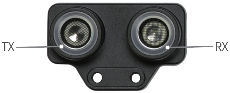
Le capteur ultrasonique 2 peut être utilisé pour détecter la distance entre un obstacle et lui. Le transmetteur à gauche émet des ondes ultrasonores, et le récepteur à droite reçoit les ondes ultrasonores réfléchies.
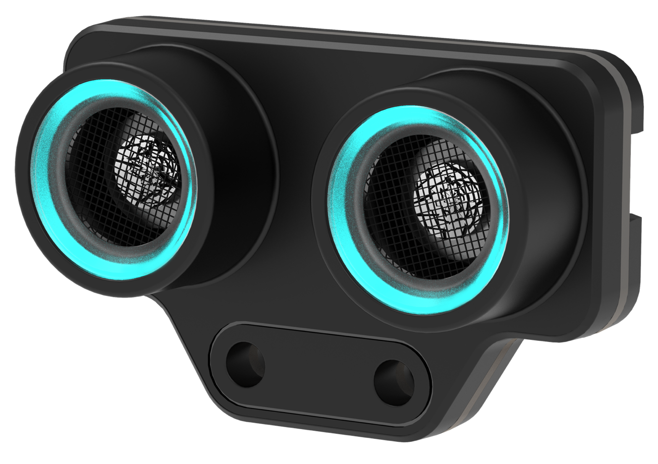
Comparé au capteur ultrasonique que nous avons développé précédemment, le capteur ultrasonique 2 est amélioré dans son boîtier, sa puce et ses LED bleues. Les LED bleues peuvent augmenter le potentiel d'expression émotionnelle et d'interaction.
Comparaison des capteurs ultrasoniques
| Capteur ultrasonique 2 | Capteur ultrasonique | |
|---|---|---|
| Boîtier en plastique pour améliorer la durabilité et la qualité | Oui | Non |
| Puce intégrée pour améliorer la stabilité de fonctionnement | Oui | Non |
| LED bleues (fonction supplémentaire) | 8 | 0 |
Spécifications
- Plage de sortie : 5–300 cm (La valeur de sortie est de 300 lorsque la distance détectée est hors de la plage de sortie.)
- Erreur de valeur de sortie : ±5%
Principe de fonctionnement
Les êtres humains peuvent entendre des sons de 20 à 20 000 Hz. Les ondes sonores avec des fréquences supérieures à 20 000 Hz sont appelées ondes ultrasonores. Les ondes sonores sont renvoyées par les obstacles qu'elles rencontrent et sont reçues par le récepteur du capteur ultrasonique. En se basant sur le temps entre la transmission et la réception, les distances entre le capteur ultrasonique et les obstacles peuvent être calculées.
Exemple de la vie réelle
- Les chauves-souris localisent les objets avec des ondes ultrasonores.

Guide de programmation
Vous pouvez utiliser mBlock 5 pour programmer le capteur ultrasonique 2. Connectez le capteur ultrasonique 2 à CyberPi, ajoutez CyberPi et connectez-le à mBlock 5, puis ajoutez l'extension Capteur ultrasonique 2. Pour plus de détails sur la façon d'ajouter CyberPi et de le connecter à mBlock 5 et sur la façon d'ajouter l'extension, consultez "Ajouter et connecter mBot2" et "Ajouter des extensions".
Détection et détermination de la distance
Pour obtenir la distance entre l'obstacle et le capteur ultrasonique 2, utilisez :
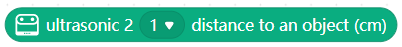
Pour déterminer si un obstacle est trouvé dans la plage de sortie de 5 cm à 300 cm, utilisez :

Généralement, les fonctions de détection et de détermination de la distance sont utilisées pour mettre en œuvre l'évitement des obstacles. Par exemple :
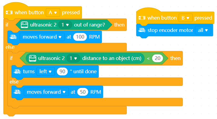
Lorsqu'aucun obstacle n'est détecté dans la plage de détection du capteur ultrasonique 2, mBot2 avance à la vitesse de 100 tours par minute ; lorsqu'un obstacle est détecté, il avance à la vitesse de 50 tours par minute ; et lorsque la distance entre l'obstacle et lui est inférieure à 20 cm, il tourne à gauche.
Expression d'émotions et d'informations
Le capteur ultrasonique 2 est équipé de huit LED bleues. En programmant leur luminosité, vous pouvez utiliser le capteur ultrasonique 2 pour exprimer différents types d'émotions et d'informations.
Exemple 1 :
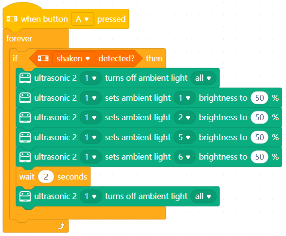
Après avoir appuyé sur le bouton A, le capteur ultrasonique 2 exprime l'émotion de bonheur en "souriant" lorsque vous le secouez. :::info Remarque : Dans cet exemple, le "sourire" est effectué en allumant les LED bleues aux positions 1, 2, 5 et 6 et en éteignant celles aux positions 3, 4, 7 et 8. :::
Alternativement, vous pouvez utiliser le bloc d'émotion fourni sur mBlock 5 pour exprimer une émotion :
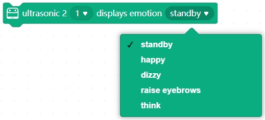
Exemple 2 :
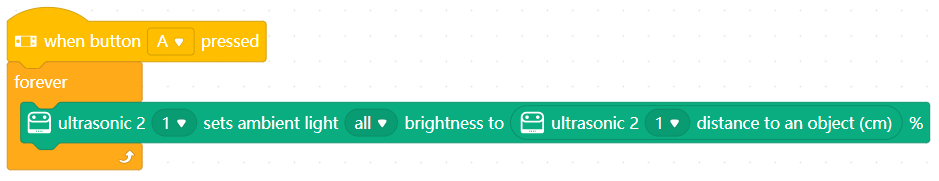
Après avoir appuyé sur le bouton A, placez un obstacle près du capteur
ultrasonique 2, puis éloignez lentement l'obstacle de celui-ci. Vous pouvez voir que les LED bleues deviennent plus lumineuses à mesure que vous éloignez l'obstacle. Une luminosité plus élevée indique une plus grande distance.
- Original: Ultrasonic Sensor 2
Capteur de gaz MQ2
Le capteur de gaz MQ2 peut facilement détecter la fumée, le gaz naturel liquéfié (GNL), le butane, le propane, le méthane, l'alcool et l'hydrogène dans l'air.
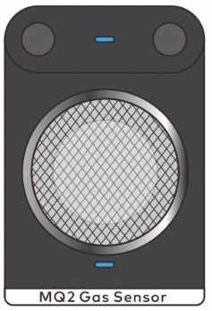
Principe de fonctionnement
Le capteur de fumée de type MQ-2 est constitué d'un matériau semi-conducteur d'oxyde d'étain. Lorsqu'il fonctionne à une température de 200 à 300 °C, l'oxyde d'étain adsorbe l'oxygène dans l'air, ce qui réduit la densité des électrons sur le semi-conducteur et augmente ainsi la résistance. Lorsqu'il entre en contact avec de la fumée, si les barrières aux joints de grains sont modifiées par la fumée, la conductivité en surface est modifiée en conséquence. De cette manière, la fumée peut être détectée. Une densité de fumée plus élevée indique une conductivité plus élevée et une résistance de sortie plus faible.
Exemple de la vie réelle
- Une alarme incendie peut détecter la fumée et le gaz inflammable.
Spécifications
- Dimensions : 24 × 36 (mm)
- Courant de fonctionnement : 160 mA
- Impédance lorsqu'il est chauffé : 33Ω
- Consommation d'énergie de préchauffage : < 800 mW
Remarque
L'erreur de détection peut être importante lorsque le module commence à fonctionner. Le module peut être préchauffé pendant cinq minutes pour de meilleures performances.
Capteur magnétique
Le capteur magnétique détecte la présence d'un aimant dans son environnement.
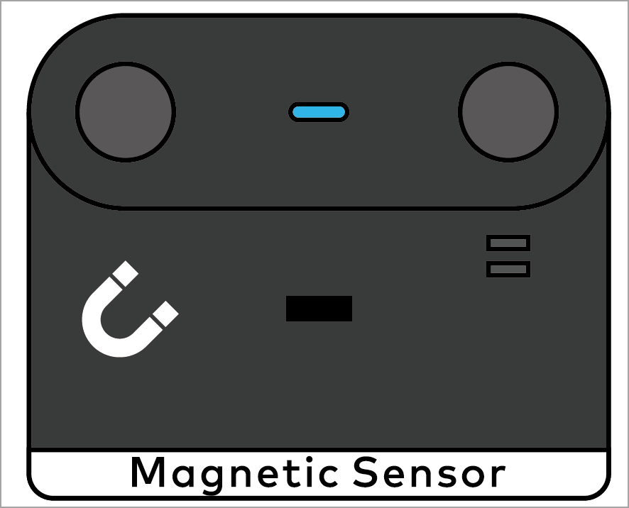
Exemple de la vie réelle
Un robot aspirateur utilise la fonction de détection du champ magnétique dans son mur virtuel pour déterminer s'il peut passer.
Spécifications
- Dimensions : 24 × 20 (mm)
- Distance de détection : <1 cm
- Courant de fonctionnement : 15 mA
Capteur d'humidité et de température
Le capteur d'humidité et de température peut détecter la température et l'humidité dans l'environnement environnant. Vous pouvez l'utiliser pour fabriquer un ventilateur intelligent, un humidificateur intelligent, et ainsi de suite.
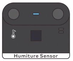
Exemple de la vie réelle
- Les appareils domotiques utilisent un capteur d'humidité et de température pour détecter la température et l'humidité, ajustant ainsi les conditions environnementales intérieures.
Spécifications
- Dimensions : 24 × 20 (mm)
- Plage de température : –40 à +125 (℃)
- Erreur de température : ±1℃
- Plage d'humidité : 0–100%
- Erreur d'humidité : ±3%
- Courant de fonctionnement : 15 mA
Capteur de température
Le capteur de température peut détecter la température de l'objet qui entre en contact avec sa sonde.
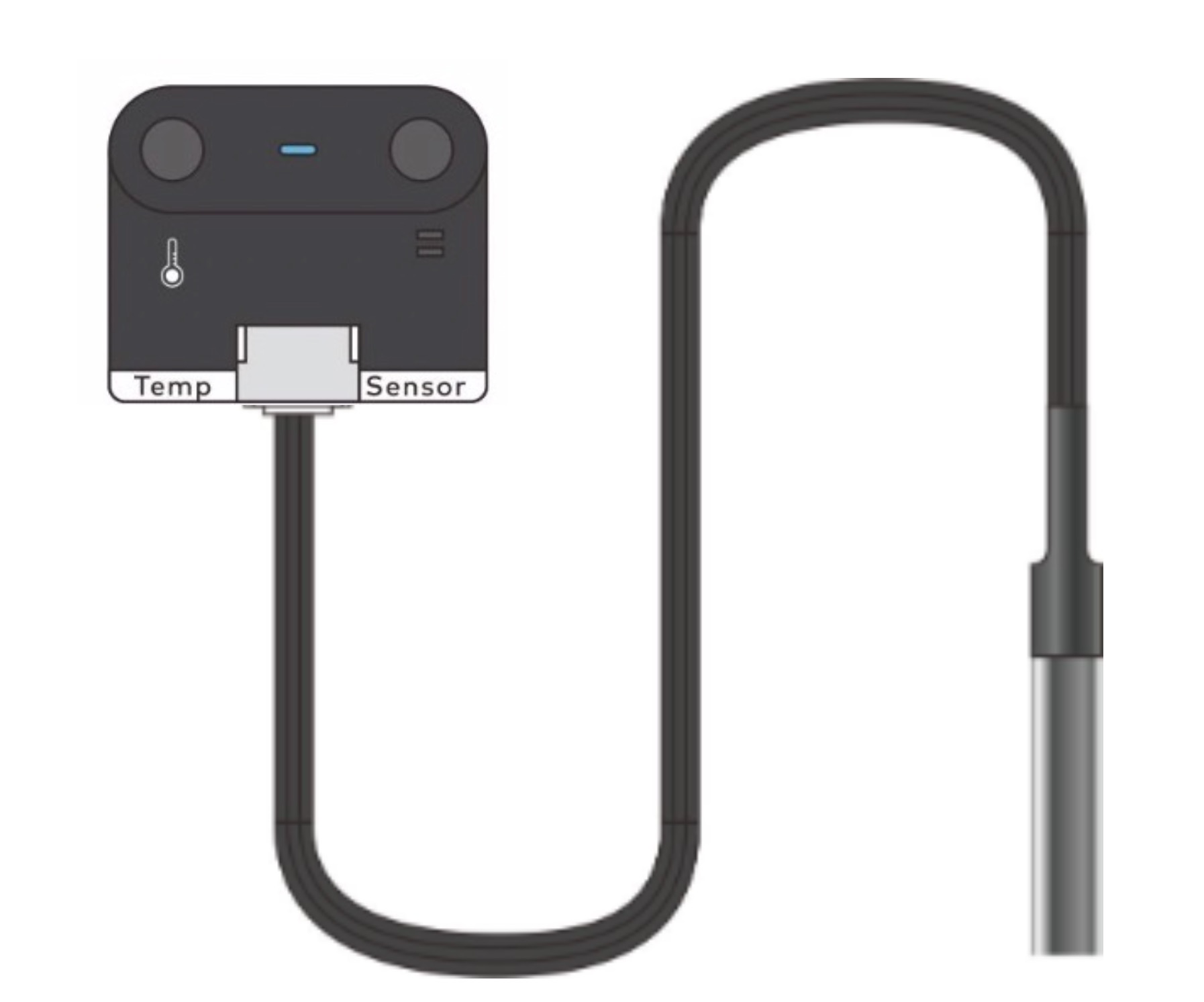
Avant d'utiliser le capteur de température, connectez-le à la sonde fournie avec celui-ci, comme indiqué dans la figure ci-dessus.
Exemple de la vie réelle
- Un thermomètre électronique utilise un capteur de température.

Spécifications
- Dimensions : 24 × 20 (mm)
- Plage de valeurs : -55 à +125 (℃)
- Erreur de valeur : ±0,5℃
- Courant de fonctionnement : 14 mA
Capteur PIR (Passive Infrared Sensor)
Le capteur infrarouge passif (capteur PIR) peut détecter si une personne ou un animal homéotherme passe à proximité.
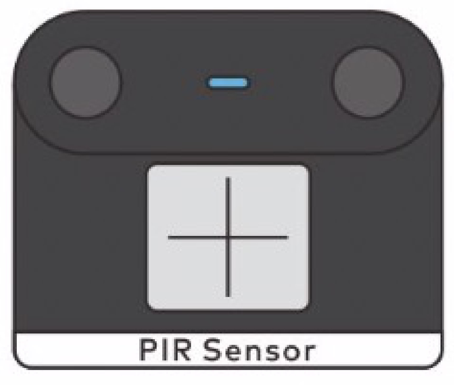
Principe de fonctionnement
Le capteur PIR utilise un capteur infrarouge pyroélectrique humain comme composant central. La température normale d'un corps humain est de 37 °C, correspondant à la lumière infrarouge de 10 μm de longueur d'onde. Le capteur PIR détecte le mouvement d'un corps humain ou d'une source de chaleur à proximité en détectant le changement de la lumière infrarouge de 10 μm de longueur d'onde.
Pour détecter de manière sensible le changement de la lumière infrarouge de 10 μm, le capteur PIR utilise un filtre de Fresnel pour concentrer la lumière infrarouge afin que le capteur puisse recevoir autant de lumière infrarouge que possible dans l'environnement.
Exemple de la vie réelle
- Un centre commercial utilise un capteur PIR sur sa porte automatique pour déterminer s'il faut ouvrir ou fermer la porte.

Spécifications
- Dimensions : 24 × 20 (mm)
- Plage de détection : 3–5 (m)
- Plage d'angle de détection sur l'axe x : 80 degrés
- Plage d'angle de détection sur l'axe y : 55 degrés
- Durée de fonctionnement après déclenchement : 3s
- Courant de fonctionnement : 15 mA
Capteur de mouvement
Le capteur de mouvement est composé d'un gyroscope à 3 axes et d'un accéléromètre à 3 axes et peut détecter le mouvement, l'accélération et les vibrations d'un objet.
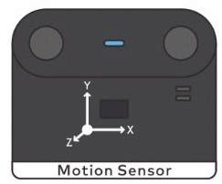
Axes et angles
| Axe | Nom de l'angle | Plage d'angle |
|---|---|---|
| X | Tangage | –180° à +180° |
| Y | Roulis | –90° à +90° |
| Z | Lacet | –180° à +180° |
Principe de fonctionnement
Si vous recherchez des gyroscopes sur Internet, vous trouverez probablement le schéma suivant.
 Il s'agit d'une théorie basée sur la conservation du moment angulaire. Un gyroscope est un mécanisme utilisé pour détecter et maintenir des directions. Il est principalement composé d'un rotor rotatif situé sur l'axe. En raison du moment angulaire du rotor, une fois que le gyroscope commence à tourner, il a tendance à résister au changement de direction. Ces gyroscopes sont utilisés dans les premiers systèmes de navigation.
Dans les produits électroniques modernes, grâce à la technologie microélectromécanique florissante et en raison de la limitation du volume, les gyroscopes basés sur les systèmes microélectromécaniques (MEMS) sont largement utilisés. Ils sont de petite taille et peuvent être directement soudés sur un PCB. C'est pourquoi nous pouvons produire un capteur de mouvement avec des dimensions de 24 × 20 mm.
Les principes de fonctionnement de ces deux types de gyroscopes sont très différents, mais ce que vous devez savoir, c'est qu'ils peuvent refléter de manière plus réaliste la posture et l'état de mouvement d'un objet dans l'espace.
Exemple de la vie réelle
- Le gyroscope utilisé dans la Nintendo Switch vous permet de jouer à des jeux sensoriels.
- L'iPhone utilise un gyroscope pour implémenter sa fonction Niveau.
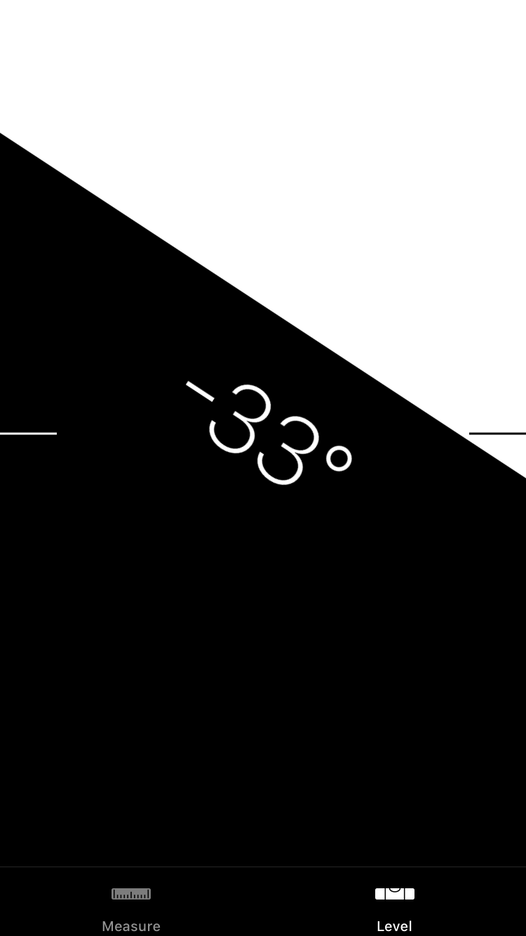
Spécifications
- Dimensions : 24 × 20 (mm)
- Précision de l'angle:±1 (degré)
- Plage de détection de l'accélération : ±8g
- Courant de fonctionnement : 18 mA
Capteur de flamme
Le capteur de flamme peut détecter une flamme et sa taille en détectant la lumière infrarouge.
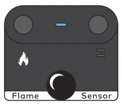
La lumière du soleil contient une grande quantité de lumière infrarouge, ce qui peut interférer gravement avec le fonctionnement du capteur de flamme, et donc le capteur de flamme ne peut pas fonctionner correctement lorsqu'il est placé en plein soleil.
Exemple de la vie réelle
- Les capteurs de flamme peuvent être d'une grande aide dans les endroits où le feu est strictement interdit.

Spécifications
- Dimensions : 24 × 20 (mm)
- Plage de valeurs : 0–100
- Erreur de consistance :
- Courant de fonctionnement : 20 mA
Capteur de distance
Le capteur de distance peut détecter la distance entre un obstacle et lui-même en détectant les ondes infrarouges.
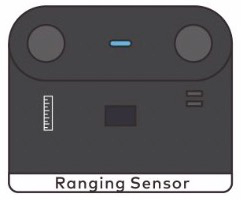
Exemple de la vie réelle
- L'iPhone utilise la détection d'ondes infrarouges pour obtenir les structures faciales et les stocker en tant que données biométriques afin de mettre en œuvre la fonction Face ID.

Spécifications
-
Dimensions : 24 × 20 (mm)
-
Plage de valeurs : 2–200 (cm)
-
Précision de la valeur : ±5%
-
Courant de fonctionnement : 33 mA
-
Original: Ranging Sensor
Capteur ultrasonique
Le capteur ultrasonique peut être utilisé pour détecter la distance entre un obstacle et lui. La sonde gauche du capteur ultrasonique émet des ondes ultrasonores et celle de droite les reçoit.
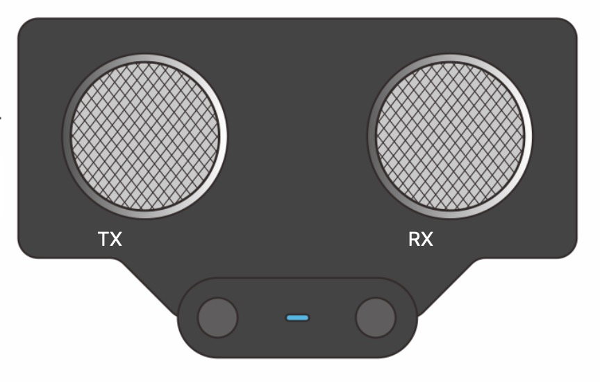
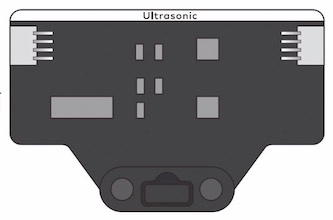
Principe de fonctionnement
Les êtres humains peuvent entendre des sons de 20 à 20 000 Hz. Les ondes sonores avec des fréquences supérieures à 20 000 Hz sont appelées ondes ultrasonores. Les ondes sonores rebondissent sur les obstacles qu'elles rencontrent et sont reçues par la sonde du capteur ultrasonique. En se basant sur le temps entre la transmission et la réception, la distance entre la sonde du capteur ultrasonique et l'obstacle peut être calculée.
Exemple de la vie réelle
- Les chauves-souris localisent les objets avec des ondes ultrasonores.

Spécifications
- Plage de valeurs : 5–300 (cm) (La valeur 300 est rapportée lorsque la valeur dépasse la plage.)
- Erreur de valeur : ±5%
- Courant de fonctionnement : 26 mA
SoundSensor
Capteur de couleur RGB double
Le capteur de couleur RGB double se compose d'une paire d'éléments sensibles à la lumière pour détecter la couleur d'un objet. Il peut faciliter le suivi de ligne des robots tout en détectant les couleurs.
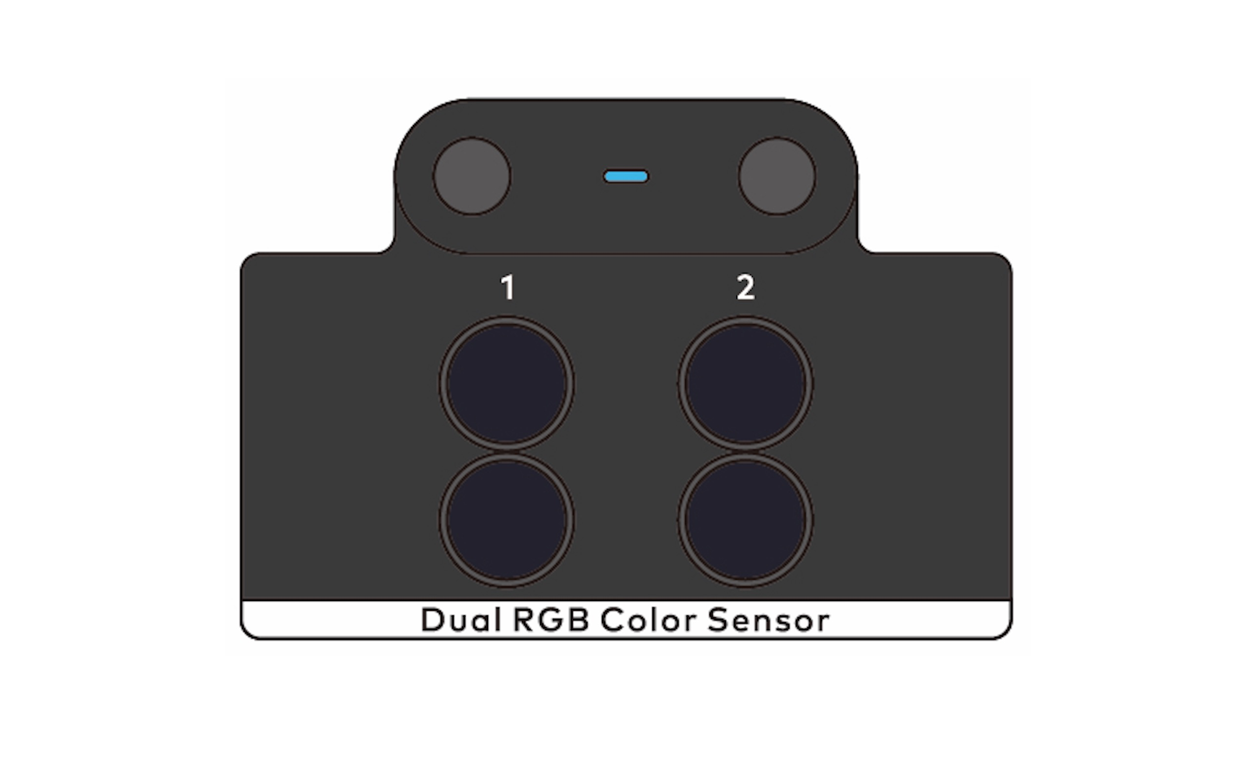
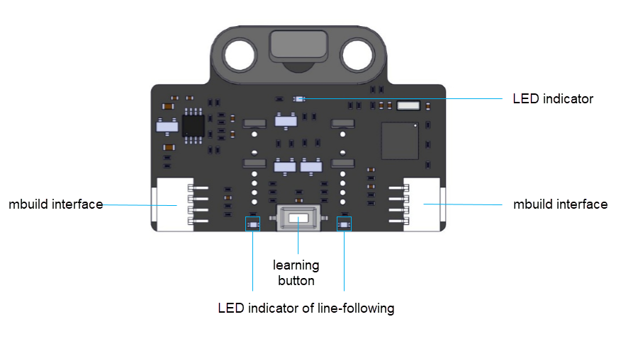
Le capteur de couleur RGB double peut fournir plusieurs types de données, y compris la sortie analogique qui indique l'intensité lumineuse, la sortie numérique qui indique les états de la ligne et de l'arrière-plan, et les valeurs de paramètres calculées pour le contrôle moteur, ce qui garantit une flexibilité suffisante tout en simplifiant votre processus d'application. Sur la base de la sortie des données, les enseignants peuvent expliquer les connaissances et les principes de fonctionnement sous différents aspects.
Le capteur de couleur RGB double fournit la fonction d'apprentissage de carte adaptative. Il définit automatiquement les seuils après avoir appris les couleurs de l'arrière-plan et de la ligne à suivre. Le micrologiciel du capteur comprend un algorithme de suivi de ligne et peut fournir directement des valeurs de paramètres pour contrôler la vitesse de rotation des moteurs, ce qui rend le suivi de ligne à haute vitesse plus facile.
Description des boutons
-
Appui simple : Aucune fonction n'est définie.
-
Double pression : Lorsque le bouton est pressé deux fois, le capteur de couleur RGB double commence à apprendre l'arrière-plan et la ligne pour le suivi de ligne.
Placez les capteurs de lumière sur l'arrière-plan de la carte de suivi de ligne et appuyez deux fois sur le bouton. Lorsque vous voyez les LED indiquant que l'état de suivi de ligne clignote rapidement, balayez les capteurs de côté à côté au-dessus de l'arrière-plan et de la ligne jusqu'à ce que les LED arrêtent de clignoter. Cela prend environ 2,5 secondes. Les valeurs de paramètres obtenues sont automatiquement stockées. Si l'apprentissage échoue, les LED clignotent lentement, et vous devez recommencer l'apprentissage.
- Appui long : Lorsque le bouton est maintenu enfoncé pendant deux à trois secondes, le capteur de couleur RGB double change la couleur des lumières de remplissage dans l'ordre du rouge, du vert et du bleu. En général, vous n'avez pas besoin de changer la couleur. La couleur est définie automatiquement après la fin de l'apprentissage.
Principe de fonctionnement
Chaque groupe de capteurs de couleur se compose d'un capteur de lumière et d'une LED RGB. Dans le monde réel, lorsque vous voyez un objet en rouge, cela signifie que l'objet absorbe plus de lumière que la lumière rouge. Par conséquent, si vous utilisez une lumière de remplissage pour éclairer un objet avec de la lumière rouge, plus l'objet est rouge, plus il réfléchit de lumière, et plus grande est la valeur de sortie du capteur de lumière. De cette manière, vous pouvez obtenir l'intensité rouge de l'objet. De même, vous pouvez changer la couleur des lumières de remplissage pour obtenir l'intensité verte et bleue de l'objet et ainsi déterminer la couleur de l'objet.
Interférences environnementales et erreurs de détection
Dans le monde physique, vous pouvez trouver des interférences environnementales et des erreurs de détection presque partout. Si un capteur de couleur doit déterminer la couleur d'un objet en fonction de l'intensité de la lumière (éclairée par une lumière de remplissage et réfléchie par l'objet) qu'il détecte, des erreurs de détection peuvent être causées car la lumière ambiante est également détectée.
Faites attention aux erreurs de détection. Lorsque vous utilisez deux capteurs de couleur RGB double pour détecter la couleur d'un objet dans le même environnement, les résultats de détection peuvent être différents. Mais en général, la différence est faible.
En pratique, les ingénieurs utilisent des algorithmes ou une conception spéciale pour éviter les interférences environnementales et les erreurs de détection. Par exemple, vous pouvez utiliser une impression 3D pour bloquer la lumière ambiante afin qu'elle n'atteigne pas l'objet à détecter et le capteur de couleur RGB double; alternativement, vous pouvez utiliser un algorithme : enregistrer l'intensité de la lumière ambiante lorsque les lumières de remplissage sont éteintes, et enregistrer immédiatement l'intensité lorsque les lumières de remplissage sont allumées ; puis calculer la différence entre ces deux valeurs d'intensité. Cette différence peut être déterminée comme l'intensité de la lumière de remplissage réfléchie par l'objet. Dans l'algorithme, l'intensité de la lumière ambiante est considérée comme presque inchangée en un très court laps de temps.
Pour les erreurs de détection, vous pouvez également utiliser un algorithme pour classer plusieurs valeurs proches comme une couleur.
Exemple de la vie réelle
- Les capteurs de couleur sont utilisés pour concevoir une ligne d'assemblage pour le tri des pièces.
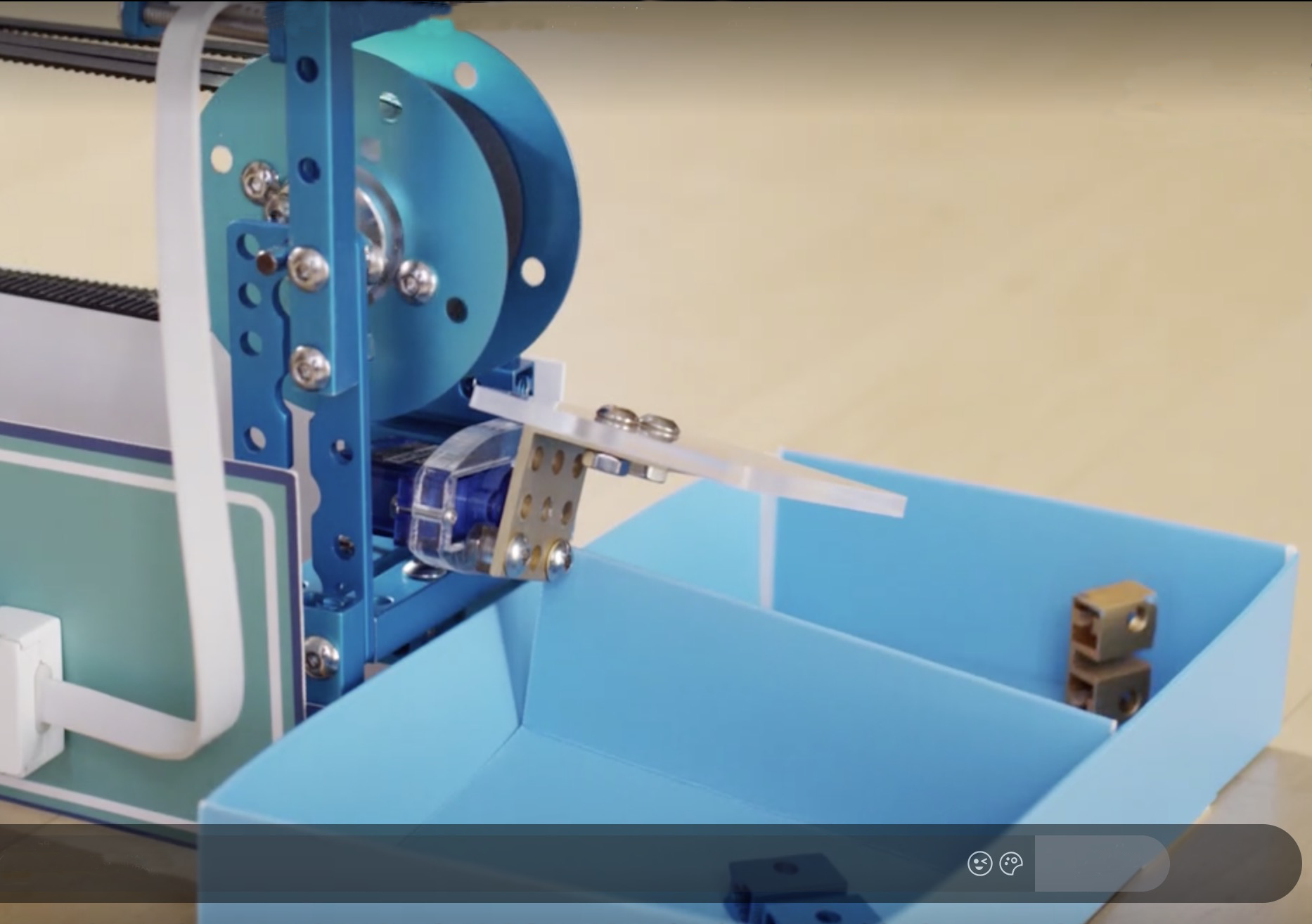
Spécifications
- Plage de détection : 5–15 (mm) de l'objet à détecter
- Courant de fonctionnement : 70 mA
Capteur de lumière
Le capteur de lumière peut détecter l'intensité de la lumière ambiante.
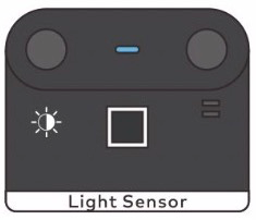
Principe de fonctionnement
Le capteur de lumière mBuild utilise une photoresistance comme composant central qui peut changer la résistance en fonction de l'intensité lumineuse. Le changement de résistance peut être détecté par le MCU, et donc le MCU peut déterminer l'intensité lumineuse dans l'environnement.
Exemples de la vie réelle
- Un capteur de lumière peut être utilisé pour faciliter le réglage de la luminosité de l'écran d'un téléphone portable.

- Les capteurs de lumière sont utilisés dans certaines lampes intelligentes pour faciliter le réglage de la luminosité en fonction de l'intensité de la lumière ambiante détectée.
Spécifications
- Dimensions : 24 × 20 (mm)
- Plage de valeurs : 0–100%
- Courant de fonctionnement : 15 mA
Capteur d'Humidité du Sol
Le capteur d'humidité du sol peut détecter le niveau d'humidité dans le sol.
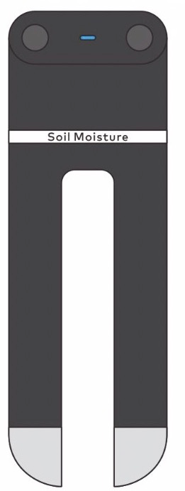
Principe de fonctionnement
Il existe deux types courants de capteurs d'humidité du sol, les capteurs capacitifs et les capteurs résistifs. Un capteur d'humidité du sol capacitif mesure le changement de capacité causé par l'humidité du sol pour estimer l'humidité du sol. Un capteur résistif estime l'humidité du sol en fonction de la résistance détectée entre les deux contacts.
La définition stricte de l'humidité du sol est le pourcentage d'eau dans le sol. Ni le capteur d'humidité du sol résistif ni le capteur capacitif ne peuvent prédire avec précision la teneur en eau dans le sol. Ils ne peuvent rapporter que des valeurs d'humidité qui sont positivement corrélées à la teneur en eau.
Le capteur d'humidité du sol mBuild est de type résistif. Lorsque l'humidité du sol augmente, l'eau peut dissoudre les ions contenus dans une partie du sol, de sorte que la résistance du sol diminue, et par conséquent, la valeur de sortie du capteur d'humidité du sol devient plus grande. Lorsque la teneur en eau dans le sol augmente davantage (dans le cas d'extrêmes, imaginez que vous jetez de la terre dans l'eau), la concentration ionique dans le sol est diluée par l'eau en excès, ce qui entraîne une diminution de la conductivité électrique et une augmentation de la résistance. Par conséquent, vous pouvez constater que le capteur d'humidité du sol produit une valeur plus petite dans l'eau pure que dans un sol humide (bien que ce dernier ait une teneur en eau significativement plus élevée) car la concentration ionique dans le sol humide est plus élevée et la résistance est plus faible.
:::tips Remarques : Le capteur d'humidité du sol mBuild est de type résistif, et il peut donc également être utilisé, dans une certaine mesure, pour détecter la résistance. Nous envisageons de développer des ports connexes à cet effet. :::
Spécifications
- Dimensions : 24 × 72 (mm)
- Plage de valeurs : 0–100
- Erreur de consistance : ±5%
- Courant de fonctionnement : 14 mA
- Source originale : Centre d'Aide Makeblock
Caméra Intelligente
La caméra intelligente peut apprendre et reconnaître des objets de couleurs vives ainsi que détecter les codes-barres et les lignes, ce qui lui permet d'être utilisée dans divers scénarios d'application, tels que le tri des déchets, le transport intelligent, le suivi d'objets et le suivi intelligent de lignes.
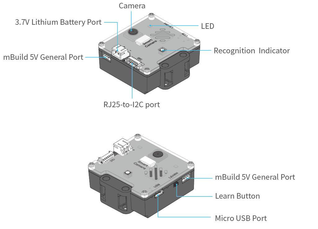
Connexion à mBot ou Halocode
En fonction du mode de câblage, la caméra intelligente peut être utilisée comme un module électronique RJ25 ou un module électronique mBuild. Après l'avoir connectée à mBot ou Halocode, vous pouvez la contrôler via mBot ou Halocode.
Connexion à mBot
Après avoir connecté la caméra intelligente à mBot, vous pouvez l'alimenter avec une batterie lithium 3,7V ou le module d'alimentation mBuild.
Méthode 1 Alimentation via le module d'alimentation mBuild (recommandée)
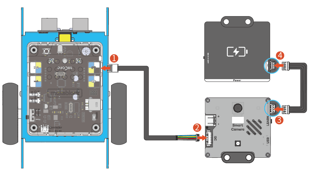
Méthode 2 Alimentation via une batterie lithium 3,7V
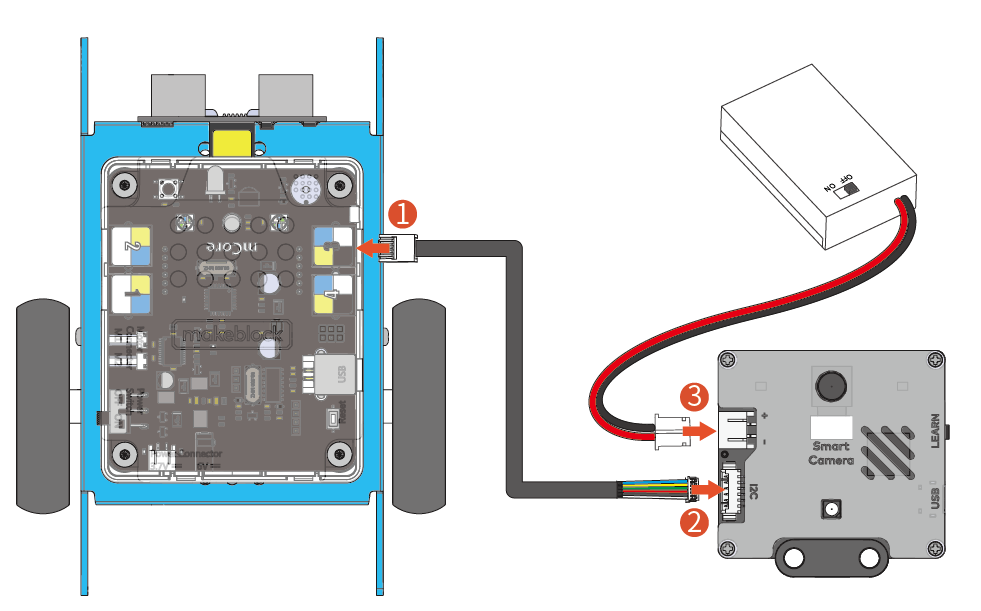
Connexion à Halocode
Remarque : Il est recommandé d'alimenter la caméra intelligente via le module d'alimentation mBuild. L'alimentation uniquement via le port USB peut affecter l'utilisation correcte du bloc.
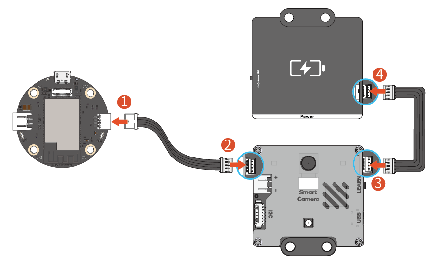
Caractéristiques
Apprentissage des couleurs
La caméra intelligente peut apprendre les objets de couleur vive et identifier les blocs de couleur après l'apprentissage, puis renvoyer leurs coordonnées, longueur et largeur. Apprenez un objet coloré comme suit :
- Maintenez le bouton d'apprentissage enfoncé jusqu'à ce que le voyant devienne rouge (orange, jaune, vert, bleu ou violet, différentes couleurs indiquent l'apprentissage d'objets différents), puis relâchez le bouton.
- Placez le bloc de couleur à apprendre devant la caméra.
- Observez le voyant à l'avant ou à l'arrière de la caméra intelligente, et déplacez lentement l'objet à apprendre jusqu'à ce que la couleur du voyant corresponde à celle de l'objet.
- Appuyez brièvement sur le bouton d'apprentissage pour enregistrer l'objet appris actuel. Après que l'apprentissage a réussi, lorsque la caméra reconnaît un objet appris, la couleur du voyant devient la même que celle de l'objet appris.
Un maximum de sept objets peut être appris et enregistré dans ce mode.
| Action | Description |
|---|---|
| Maintien enfoncé jusqu'à ce que la lumière rouge s'allume | Commence à apprendre la couleur 1 |
| Maintien enfoncé jusqu'à ce que la lumière orange s'allume | Commence à apprendre la couleur 2 |
| Maintien enfoncé jusqu'à ce que la lumière jaune s'allume | Commence à apprendre la couleur 3 |
| Maintien enfoncé jusqu'à ce que la lumière verte s'allume | Commence à apprendre la couleur 4 |
| Maintien enfoncé jusqu'à ce que la lumière cyan s'allume | Commence à apprendre la couleur 5 |
| Maintien enfoncé jusqu'à ce que la lumière bleue s'allume | Commence à apprendre la couleur 6 |
| Maintien enfoncé jusqu'à ce que la lumière violette s'allume | Commence à apprendre la couleur 7 |
Après l'apprentissage, vous pouvez utiliser le programme suivant pour suivre le bloc de couleur (bloc de couleur 1).
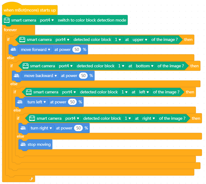
Remarque
- Plus la couleur de l'objet appris est vive, plus la reconnaissance est précise.
Exemple d'avertissement : apprentissage d'une peluche panda

- La caméra intelligente peut apprendre et enregistrer sept objets, qui doivent être facilement distinguables par leur couleur.
Exemple d'avertissement : apprentissage d'une balle jaune et d'un chapeau jaune
 Bon exemple : apprentissage d'une balle orange et d'une balle verte
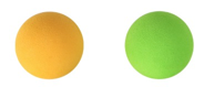
- Basculez la caméra intelligente en mode détection de blocs de couleur pour détecter les coordonnées et la taille du bloc de couleur.
- La caméra intelligente peut prévenir les interférences lumineuses. Cependant, une lumière changeante peut encore affecter la précision de la reconnaissance. Les résultats d'apprentissage précédents peuvent ne pas réussir à être utilisés dans un nouvel environnement. Voici quelques solutions:
- Réinitialisez la balance des blancs
- Allumez la LED avant l'apprentissage ou la reconnaissance
- Réglez les paramètres détaillés dans PixyMon
- Utilisez un abat-jour pour couvrir les blocs
Reconnaissance de codes-barres et de lignes
La caméra intelligente peut détecter simultanément les codes-barres, les lignes et les routes secondaires sans apprentissage.
Basculez la caméra intelligente en mode suivi de ligne/étiquette pour détecter et renvoyer les informations de coordonnées des codes-barres, des lignes et des routes secondaires.
Reconnaissance des codes-barres
Des cartes et autocollants de codes-barres sont inclus dans le package. Cliquez pour télécharger les cartes de codes-barres. 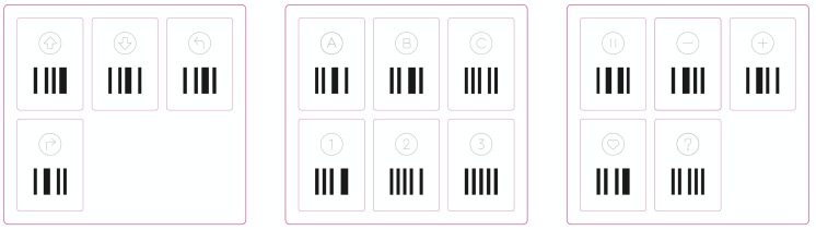 Vous pouvez placer les cartes sur la carte de suivi de ligne.
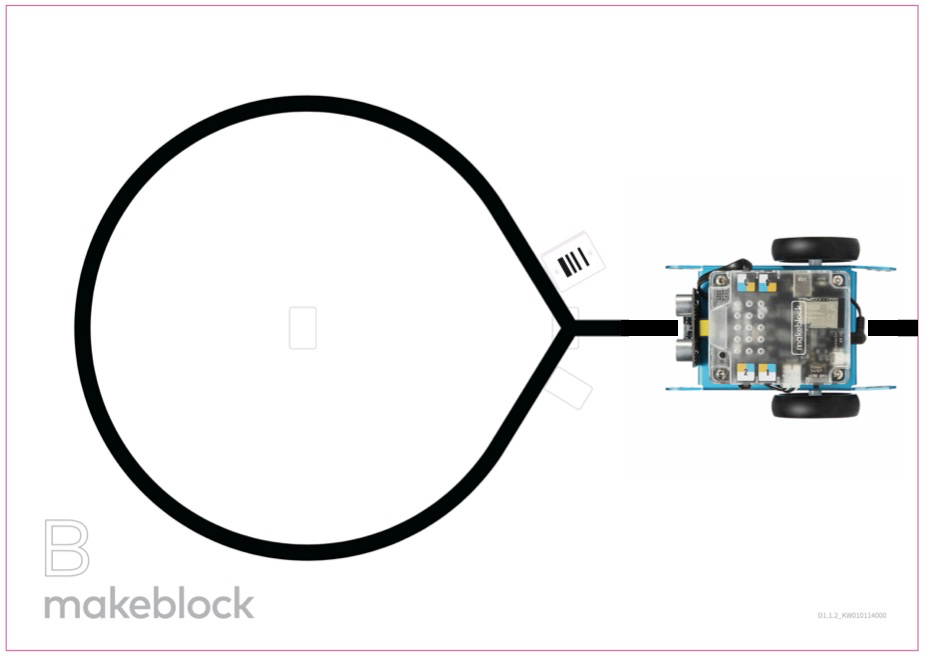 Reconnaissance des lignes et des routes secondaires
La caméra intelligente peut détecter les lignes et le nombre de routes secondaires, et renvoyer les coordonnées, directions et le nombre de routes secondaires.
Reconnaissance des lignes et des routes secondaires
La caméra intelligente peut détecter les lignes et le nombre de routes secondaires, et renvoyer les coordonnées, directions et le nombre de routes secondaires.
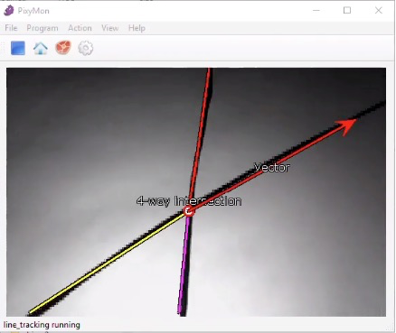 Note
Note
- Vous pouvez définir le mode de suivi de ligne en ligne sombre sur clair ou ligne claire sur sombre dans le programme.
- La caméra intelligente filtrera par défaut les lignes étroites. Consultez le guide de l'utilisateur de PixyMon pour modifier les paramètres par défaut.
PixyMon
La caméra intelligente prend en charge le logiciel PixyMon. Vous pouvez utiliser PixyMon pour afficher l'écran de la caméra, ajuster les fonctions de la caméra intelligente et régler certains paramètres pour explorer des fonctionnalités plus complexes. Suivez les étapes ci-dessous pour installer et utiliser PixyMon :
- Cliquez sur les liens suivants pour télécharger PixyMon. Télécharger PixyMon pour Windows Télécharger PixyMon pour Mac
- Double-cliquez sur le package d'installation et suivez les instructions pour l'installer.
- Après l'installation, ouvrez PixyMon.
- Connectez la caméra intelligente à l'ordinateur via un câble USB.
- Après avoir vu la barre d'état indiquant connecté comme indiqué ci-dessous, vous pouvez commencer à explorer la caméra intelligente avec PixyMon.
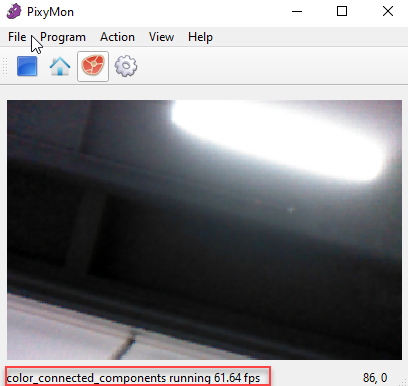 Remarque : Pour faciliter l'utilisation du module, nous n'avons pas développé de nombreuses fonctions sur les blocs. Si vous souhaitez contrôler la caméra intelligente via les blocs pour implémenter plus de fonctionnalités, utilisez le Constructeur d'Extensions mBlock 5.
Documentation du Constructeur d'Extensions mBlock
Remarque : Pour faciliter l'utilisation du module, nous n'avons pas développé de nombreuses fonctions sur les blocs. Si vous souhaitez contrôler la caméra intelligente via les blocs pour implémenter plus de fonctionnalités, utilisez le Constructeur d'Extensions mBlock 5.
Documentation du Constructeur d'Extensions mBlock
Paramètres
- Dimensions : 48 × 48 (mm)
- Résolution : 640 x 480
- Champ de vision : 65.0 degrés
- Longueur focale effective : 4.65±5% mm
- Vitesse de reconnaissance : 60 ips
- Distance de reconnaissance : 0.25–1.2 (m)
- Résistance à la chute : 1m
- Alimentation : Batterie lithium 3,7V ou module d'alimentation mBuild 5V
- Plage de consommation électrique : 0.9–1.3W
- Température de fonctionnement : -10℃–55℃
Programmes d'exemple
Programmes d'exemple de caméra intelligente
Exemple 1 : Suivi de blocs de couleur 1 – Suivi de la position des blocs de couleur
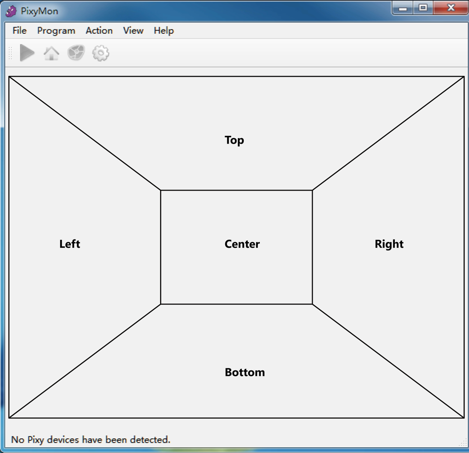
Dans cet exemple, mBot se déplace en suivant le bloc de couleur spécifié. Les moteurs tournent en fonction de la position du bloc de couleur dans l'image capturée par la caméra intelligente. Ils cessent de tourner lorsque le bloc de couleur est détecté au centre de l'image ou lorsqu'aucun bloc de couleur n'est détecté.
Notez que la manière dont vous installez la caméra intelligente affecte le suivi du bloc de couleur et donc le mouvement de mBot. La figure suivante montre un exemple de la manière dont la caméra intelligente peut être installée.
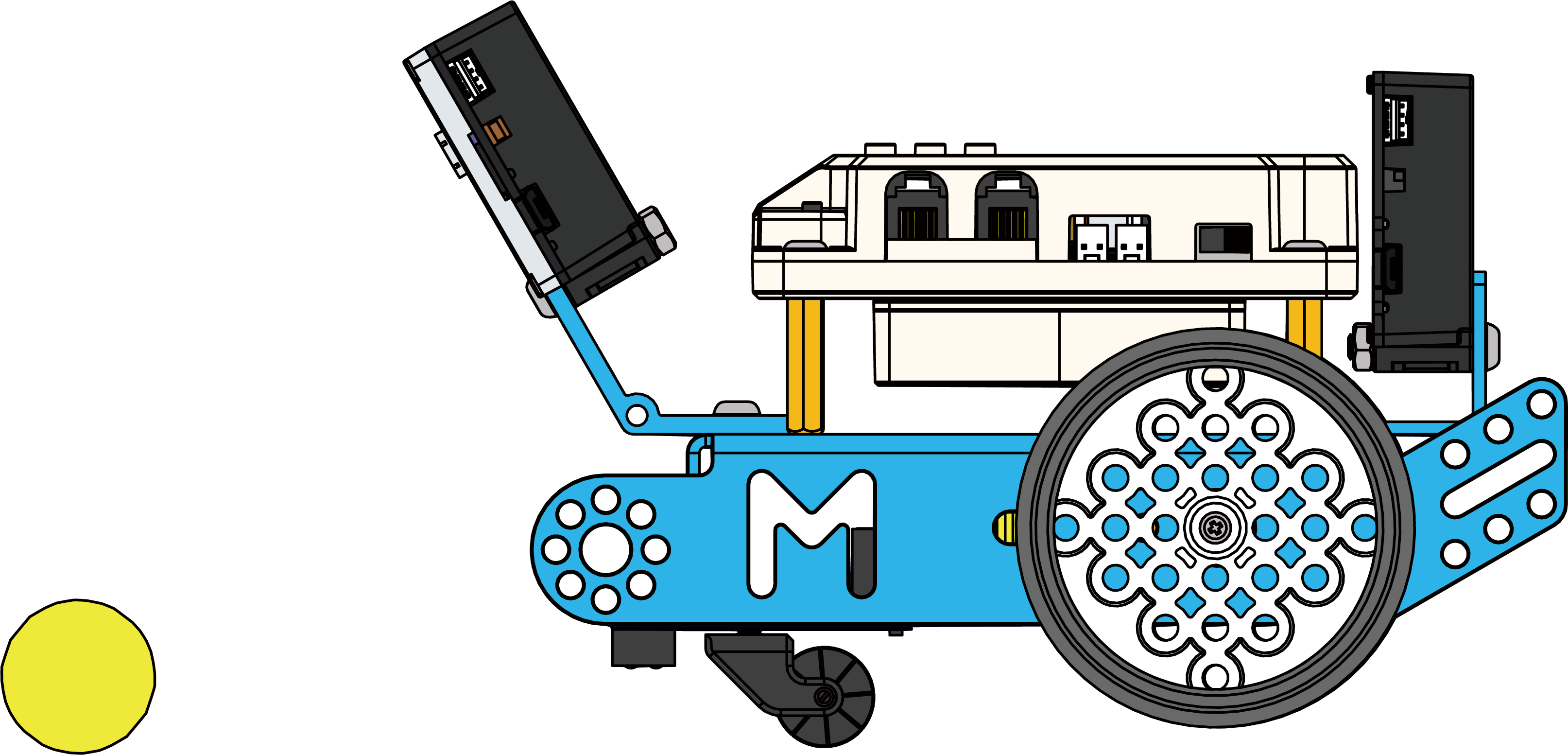
Détails du programme
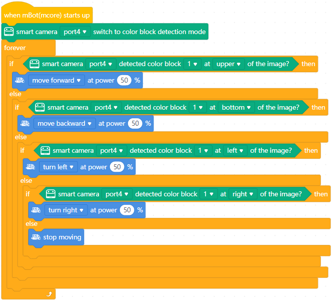
Exemple 2 : Suivi de blocs de couleur 2 – Suivi des coordonnées des blocs de couleur
Dans cet exemple, la position (définie comme A) du bloc de couleur dans l'image capturée est obtenue, et la position cible est définie comme B. Les moteurs tournent en fonction de la différence entre A et B, où la différence est calculée en fonction des coordonnées de A et B. De cette manière, un suivi plus précis est effectué. La manière dont mBot se déplace en suivant les coordonnées des blocs de couleur est similaire à celle dont il se déplace en suivant les positions des blocs de couleur.
Détails du programme
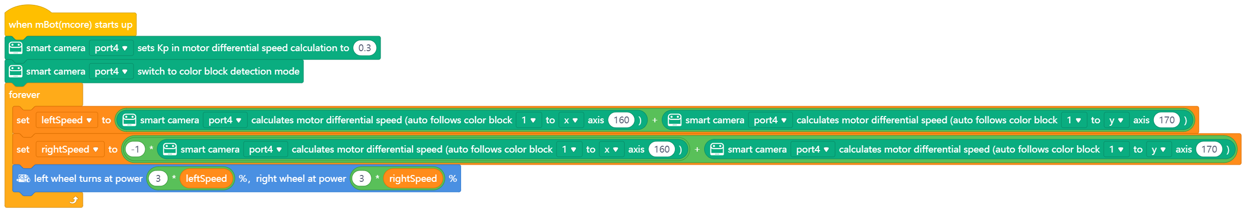
Exemple 3 : Suivi de ligne
La caméra intelligente peut reconnaître les segments de ligne. Les moteurs tournent en fonction de la vitesse différentielle calculée en fonction de l'écart du segment de ligne par rapport au centre de l'image capturée.
En mode de suivi de ligne, il est recommandé d'installer la caméra intelligente parallèlement au segment de ligne à reconnaître.
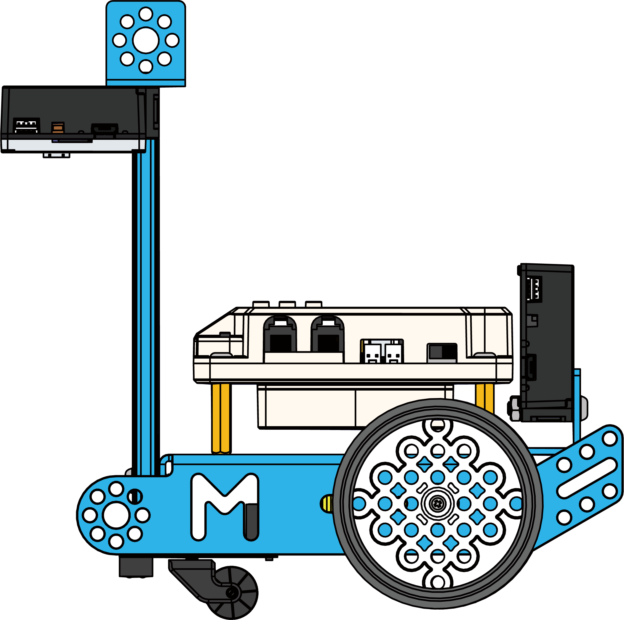
Détails du programme
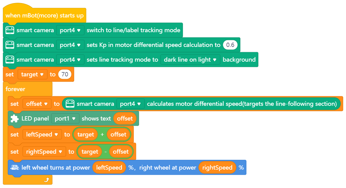 **Remarque : **
- Kp : Sensibilité dans la prise de virage. Lorsque la vitesse initiale est plus élevée ou que le virage est plus prononcé, un Kp plus grand est nécessaire.
- cible : vitesse initiale
- offset : écart par rapport à la ligne à suivre. Une valeur positive indique un écart vers la gauche de la ligne, et une valeur négative indique un écart vers la droite de la ligne.
Matrice LED bleue 8x16
La matrice LED bleue 8x16 peut afficher des animations, des émoticônes, des textes ou des chiffres. Chaque point de la matrice contient une LED, qui peut être contrôlée individuellement.
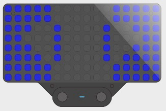
Exemple dans la vie réelle
- Les affichages d'informations de vol utilisés dans les aéroports sont d'énormes matrices LED.

Spécifications
- Dimensions : 64 × 44 (mm)
- Courant de fonctionnement : 150 mA
- Texte original : https://www.yuque.com/makeblock-help-center-en/cyberpi/led-matrix
LED RVB
La LED RVB est programmable. Vous pouvez l'allumer dans différentes couleurs et régler sa luminosité par programmation.
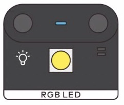
Exemples de la vie réelle
- Une LED monochrome est utilisée sur une lampe torche.
- Les LED sont également utilisées dans le clavier d'un ordinateur portable de jeu.

Spécifications
- Dimensions : 24 × 20 (mm)
- Courant de fonctionnement : 15-73 (mA)
- Texte original : https://www.yuque.com/makeblock-help-center-en/cyberpi/rgb_led
Pilote LED
Le pilote LED peut piloter divers accessoires lumineux, notamment des LED, des bandeaux LED et des anneaux LED.
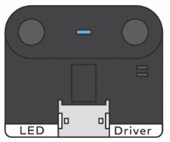
Paramètres
Dimensions : 24 mm × 20 mm Courant de référence : dépend de la charge Accessoires pris en charge : Mini bande LED et anneau
- Texte original : https://www.yuque.com/makeblock-help-center-en/cyberpi/led_driver
Speaker
The speaker can play various preset sounds. You can easily store your audio files in the module and play them through corresponding blocks.
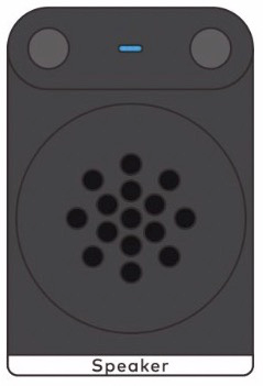
Store user-defined audio files
1. Connect the module to a PC.
Connect the speaker module to a PC by using a Micro USB cable. Use the Micro USB port of the module and a USB port of the PC. After the successful connection, the PC displays the disk of the module, and you can open the disk to view the files stored on it.
2. Store an audio file.
Drag the audio file that you want to play by the speaker to the disk. :::info **Note: **The disk space of the module is limited. It may fail to store a large file. It is recommended that you compass a large file before storing it on the disk. :::
3. Change the file name (# Haut-parleur
Le haut-parleur peut jouer divers sons prédéfinis. Vous pouvez facilement stocker vos fichiers audio dans le module et les lire grâce aux blocs correspondants.
Stockage de fichiers audio définis par l'utilisateur
1. Connectez le module à un PC.
Connectez le module haut-parleur à un PC à l'aide d'un câble Micro USB. Utilisez le port Micro USB du module et un port USB du PC. Après la connexion réussie, le PC affiche le disque du module, et vous pouvez ouvrir le disque pour voir les fichiers qui y sont stockés.
2. Stockez un fichier audio.
Faites glisser le fichier audio que vous souhaitez lire par le haut-parleur sur le disque. :::info Remarque : L'espace disque du module est limité. Il peut échouer à stocker un gros fichier. Il est recommandé de compresser un gros fichier avant de le stocker sur le disque. :::
3. Modifiez le nom du fichier (étape importante).
En raison de la conception matérielle, le module haut-parleur ne peut identifier qu'un fichier audio que par les quatre premiers caractères (lettres anglaises, chiffres ou ponctuations) de son nom de fichier. Pour lire un fichier audio, vous devez changer le nom du fichier au format spécial, c'est-à-dire une combinaison de 4 chiffres de caractères anglais, de chiffres ou de ponctuations. Les exemples suivants décrivent quelques exemples pour vous aider à changer un nom de fichier. Les noms du côté gauche sont les originaux, et ceux du côté droit sont ceux après le changement.
- 龙的传人.mp3 ------------------> ldcr.mp3
- 改革春风吹满地.mp3 ---------> ggcf.mp3
- happy birthday.mp3 ----------> M001.mp3
Après avoir changé les noms des fichiers audio, vous pouvez lire les fichiers audio en utilisant les blocs correspondants sur mBlock 5.
Lecture de fichiers audio définis par l'utilisateur
mBlock 5 fournit les deux blocs suivants pour lire les fichiers audio :

 Exemple :
 Ce bloc est utilisé pour lire le fichier audio nommé "ldcr" par le premier haut-parleur connecté.
Restaurer les fichiers audio par défaut du haut-parleur
Les mauvais fonctionnements peuvent endommager la bibliothèque de sons prédéfinis, ce qui entraîne l'impossibilité de jouer les sons prédéfinis. Ci-dessous se trouve le dernier package compressé des fichiers audio par défaut. Vous pouvez le télécharger et le décompresser sur le disque du haut-parleur pour remplacer les fichiers endommagés. Suivez ces étapes :
- Connectez le haut-parleur à l'ordinateur avec un câble USB (le haut-parleur est reconnu comme un lecteur USB).
- Formatez le lecteur USB.
- Téléchargez et décompressez le package sons prédéfinis ci-dessous, puis copiez tous ses fichiers audio à la racine de l'USB.
- Sélectionnez 'Éjecter en toute sécurité le lecteur USB' puis débranchez le module haut-parleur de l'ordinateur.
[Preset sounds.rar](https://www.yuque.com/attachments/yuque/0/2021/rar/757912/1618301500291-82ccc3b7-46cb-43b8-9c6d-9911b3122c3f.rar?_lake_card=%7B%22src%22%3A%22https%3A%2F%2Fwww.yuque.com%2Fattachments%2Fyuque%2F0%2F2021%2Frar%2F757912%2F1618301500291-82ccc3b7-46cb-43b8-9c6d-9911b3122c3f.rar%22%2C%22name%22%3 important step). Due to hardware design, the speaker module can identify an audio file only by the first four characters (English characters, numbers, or punctuations) of its file name. To play an audio file, you need to change the file name to the special format, that is, a 4-digit combination of English characters, numbers, or punctuations. The following describes some examples to help you change a file name. The names on the left side are the original ones, and those on the right side are the ones after the change.
- 龙的传人.mp3 ------------------> ldcr.mp3
- 改革春风吹满地.mp3 ---------> ggcf.mp3
- happy birthday.mp3 ----------> M001.mp3
After changing the names of audio files, you can play the audio files by using the corresponding blocks on mBlock 5.
Play user-defined audio files
mBlock 5 provides the following two blocks for playing audio files:
Example:
This block is used to play the audio file named "ldcr" by the first speaker connected.
Restore the default audio files of the speaker
Misoperations may damage the preset sound library, causing the failure to play the preset sounds. Below is the latest compressed package of the default sound files. You can download and decompress it on the disk of the speaker to replace the damaged files. Follow these steps:
- Connect the speaker to the computer with a USB cable (the speaker is recognized as a USB drive).
- Format the USB drive.
- Download and decompress the preset sounds package below and then copy all its audio files to the USB root directory.
- Select 'Safely eject USB drive' and then unplug the speaker module from the computer.
Parameters
- Dimensions: 24 × 36 (mm)
- Total memory size: 16M
- Supported audio format: mp3
- Connector type: Micro-USB
- Rated operating current: 400 mA
Pilote de servomoteur
Le pilote de servomoteur peut piloter tous les types de servomoteurs à 180 degrés, en contrôlant le degré de rotation. Les broches, de gauche à droite, sont définies comme sortie numérique, VCC et GND.

Spécifications
- Dimensions : 24 × 24 (mm)
- Courant de fonctionnement : < 1A
- Texte original : https://www.yuque.com/makeblock-help-center-en/cyberpi/servo-driver
Pilote de moteur
Le pilote de moteur peut piloter divers moteurs CC et vous pouvez l'utiliser pour contrôler la vitesse de rotation et le sens de rotation d'un moteur CC.
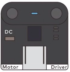
Exemples de la vie réelle
- Des pilotes de moteur sont utilisés sur les voitures Tesla.

- Un moteur permet à un sèche-cheveux de sécher vos cheveux avec de l'air.
Spécifications
- Dimensions : 24 × 24 (mm)
- Courant de fonctionnement : < 1A
- Texte original : https://www.yuque.com/makeblock-help-center-en/cyberpi/motor_driver
Contrôleur Bluetooth
En s'associant aux robots, aux cartes de commande principales, aux modules Bluetooth et aux clés Bluetooth de Makeblock, le contrôleur Bluetooth peut être utilisé pour contrôler à distance une gamme de projets.
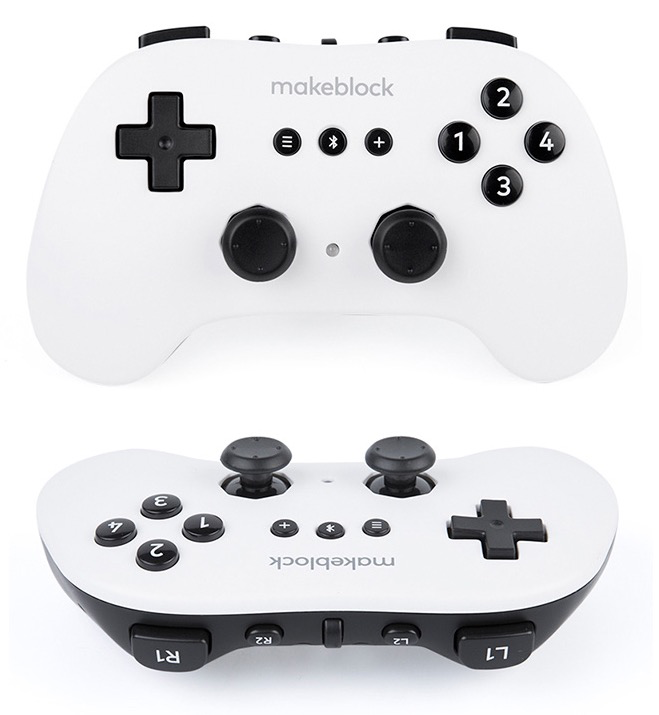
Le contrôleur Bluetooth est principalement utilisé pour le contrôle de robot dans les sessions manuelles de la compétition de robotique MakeX.
Prise en main
Installation des piles
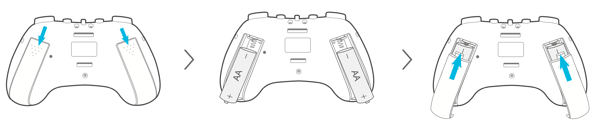 *Remarques : Lorsque l'indicateur est rouge fixe, cela indique que la batterie est faible et doit être remplacée à temps. *
Appairage Bluetooth
Allumez le contrôleur Bluetooth. L'indicateur clignote lentement en bleu.
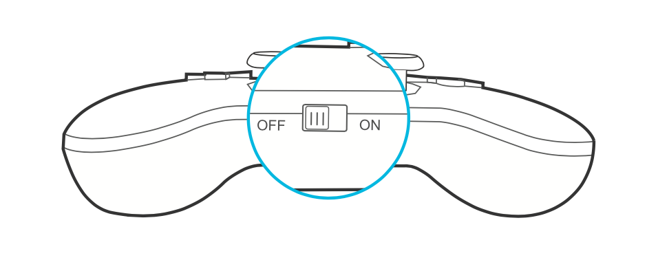 Placez le contrôleur à proximité du module Bluetooth du mBot et appuyez sur le bouton
  jusqu'à ce que l'indicateur clignote rapidement. Relâchez ensuite le bouton et l'appairage est effectué automatiquement.
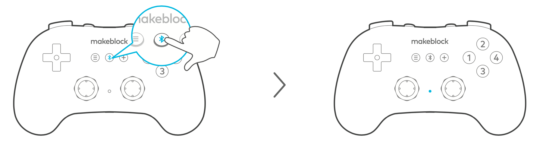
Ajout d'extensions
Lorsque vous utilisez le contrôleur Bluetooth pour contrôler CyberPi, mBot2, etc., vous devez ajouter les extensions correspondantes sur mBlock5 en premier lieu.
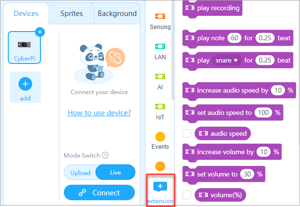
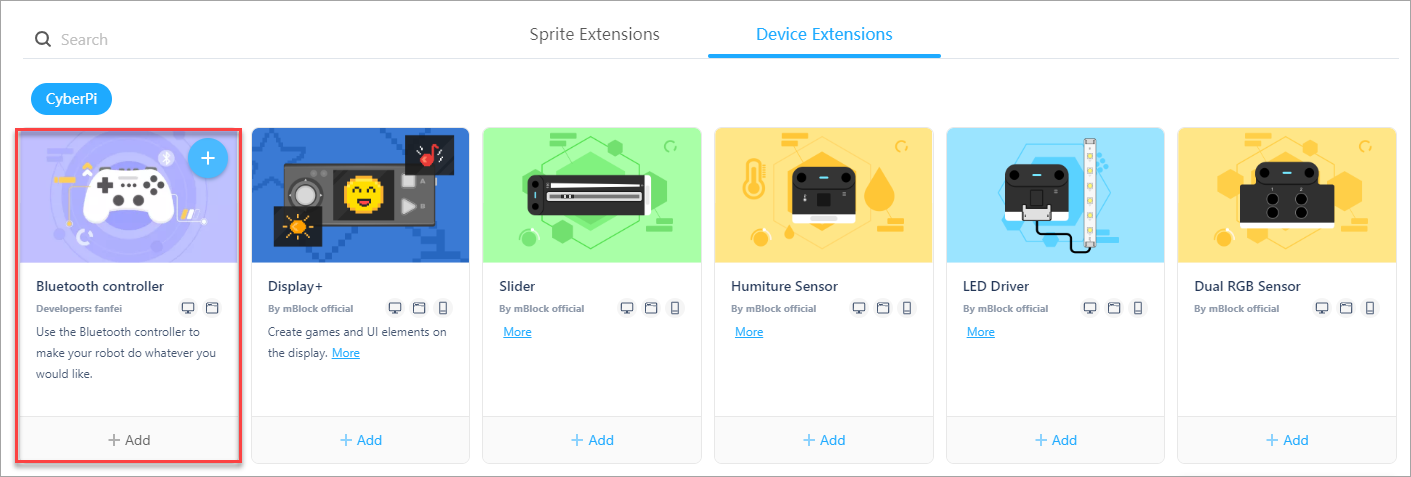
Commencez à programmer
Après avoir ajouté l'extension, vous pouvez écrire des programmes avec les blocs de l'extension, afin de pouvoir contrôler des produits tels que CyberPi et mBot2 avec un contrôleur Bluetooth.
Programmes d'exemple
La version Bluetooth de mBot ne comporte pas de programmes préinstallés pour le contrôleur Bluetooth. Donc, si vous voulez contrôler mBot avec le contrôleur Bluetooth, vous devez écrire un programme dans mBlock5 et le télécharger sur mBot.
Pour plus de détails et de programmes d'exemple sur la façon d'associer et de contrôler mBot avec le contrôleur Bluetooth, veuillez vous référer au fichier ci-dessous. mBot蓝牙手柄代码.zip
| Fonctions du contrôleur Bluetooth | |
|---|---|
| 1.Utiliser le joystick pour déplacer mBot | |
| Déplacer le joystick gauche | mBot se déplace dans la même direction que le joystick et sa vitesse de déplacement dépend de la distance à laquelle le joystick est poussé. 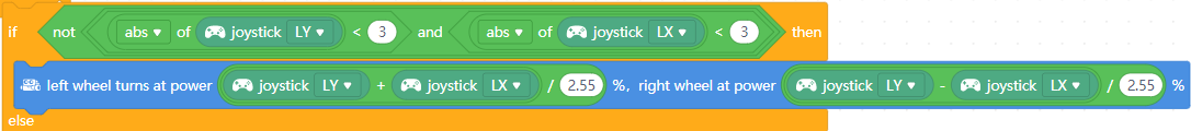 |
| 2.Utiliser les boutons pour déplacer mBot | |
| Appuyer sur la touche fléchée ↑ | Avance à une puissance de 100 % 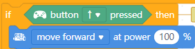 |
| Appuyer sur la touche fléchée ↓ | Recule à une puissance de 100 % 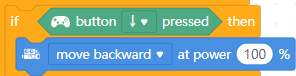 |
| Appuyer sur la touche fléchée ← | Tourne à gauche à une puissance de 100 % 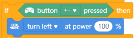 |
| Appuyer sur la touche fléchée → | Tourne à droite à une puissance de 100 % 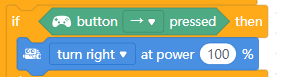 |
| 3.Utiliser les boutons pour faire tourner mBot | |
| Appuyer sur le bouton L1 | Tourne de droite à gauche 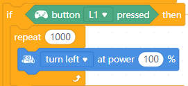 |
| Appuyer sur le bouton R1 | Tourne de gauche à droite 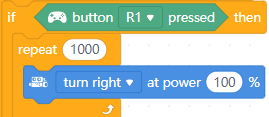 |
| 4.Utiliser les boutons pour contrôler la couleur des LED | |
| Appuyer sur le bouton numéro 1 | Toutes les LED s'allument en rouge 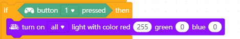 |
| Appuyer sur le bouton numéro 2 | Toutes les LED s'allument en vert  |
| Appuyer sur le bouton numéro 3 | Toutes les LED s'éteignent 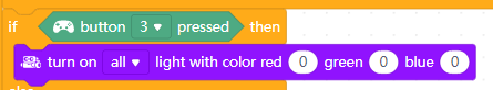 |
| Appuyer sur le bouton numéro 4 | Toutes les LED s'allument en bleu  |
| Appuyer sur plusieurs boutons numériques | Toutes les LED s'allument en couleur mixte |
| 5.Utiliser les boutons pour contrôler le buzzer | |
| Appuyer sur le bouton L2 | Jouer la note D5 pendant 0,25 temps  |
| Appuyer sur le bouton R2 | Jouer la note A3 pendant 0,5 temps  |
Spécifications
- Matériau : ABS
- Version Bluetooth : 4.0
- Distance de transmission : 20 m
- Capacité anti-interférence : 80 contrôleurs Bluetooth peuvent fonctionner ensemble sans s'interférer les uns les autres.
- Alimentation : deux piles 5AA
Télécharger le manuel
蓝牙手柄_说明书_十国语言_D1.3.9_KD010194000_View.pdf
Télécommande infrarouge
La télécommande infrarouge peut fonctionner avec le transcepteur IR mBuild. mBlock 5 a fourni le bloc permettant de détecter si une touche de la télécommande infrarouge est pressée.
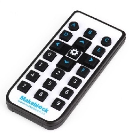
:::info Remarque : La télécommande infrarouge est alimentée par une pile bouton. En général, elle est livrée avec une pile et vous devez retirer la feuille d'isolation avant de l'utiliser. :::
Spécifications
- Dimensions : 90 × 40 × 12 (mm)
- Bande de fréquence : 940 nm
- Protocole pris en charge : NEC
- Portée de transmission : 8 m
- Alimentation : utilisation d'une pile bouton CR2025
- Durée de vie : plus de 200 mille fois
mBot2 LiPo Rechargeable Battery Enhancement Pack
The mBot2 Lithium-ion Polymer (LiPo) Rechargeable Battery Enhancement Pack is a replaceable battery pack for the MakeX Explorer competition. The pack comes to address the limitations of the insufficient power output and short battery life of mBot2 under high-load scenarios. And you can quickly replenish the power with multiple battery packs.
Specifications
| ** Parameters** | Description |
|---|---|
| Model No. | HL 21700-2P |
| Rated voltage | 3.7V |
| Capacity | 8000mAh |
| Watt hour | 29.6Wh |
Features
- Replaceable; independent charging
- Larger capacity, longer battery life
- Higher power output for scenarios with higher load requirements
Examples
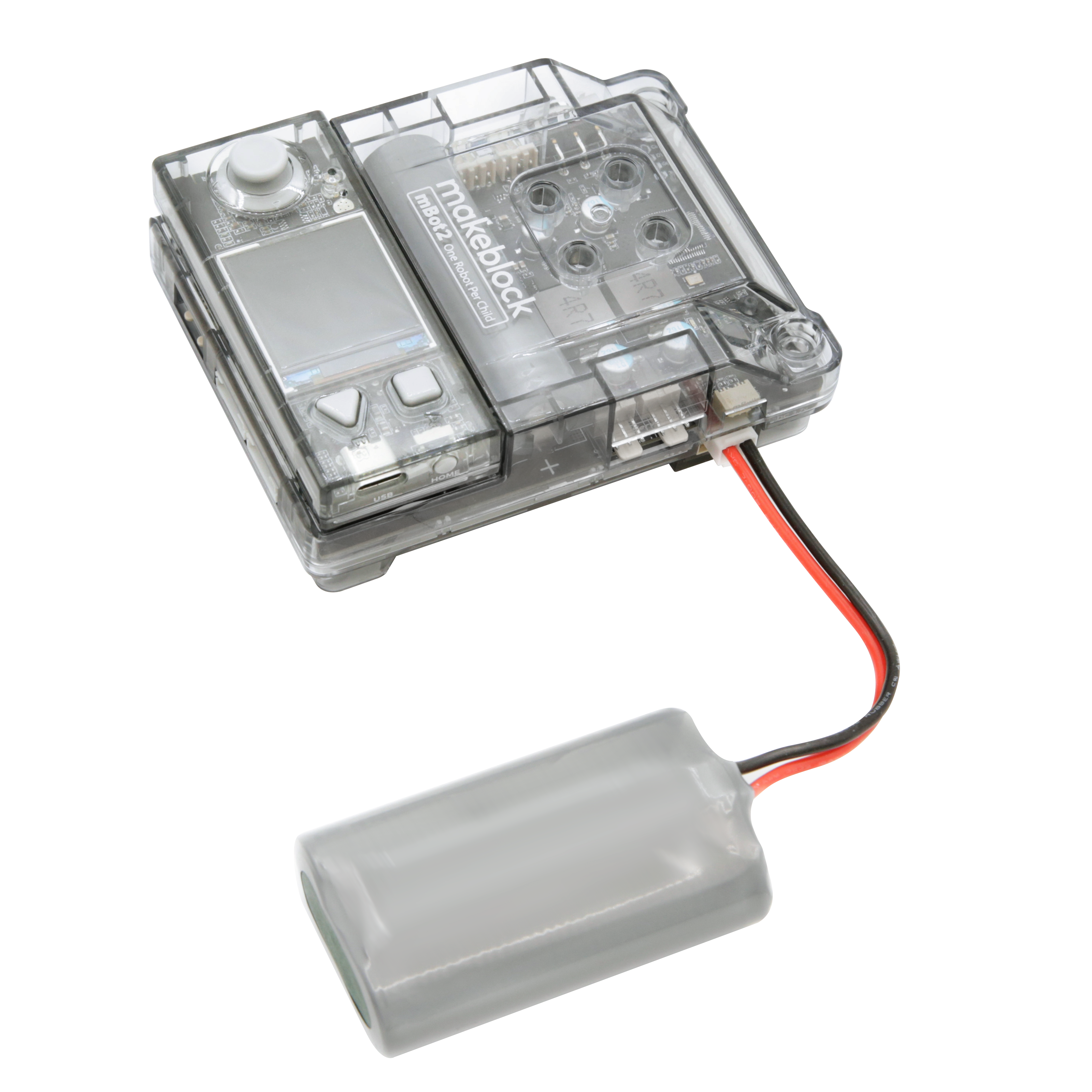
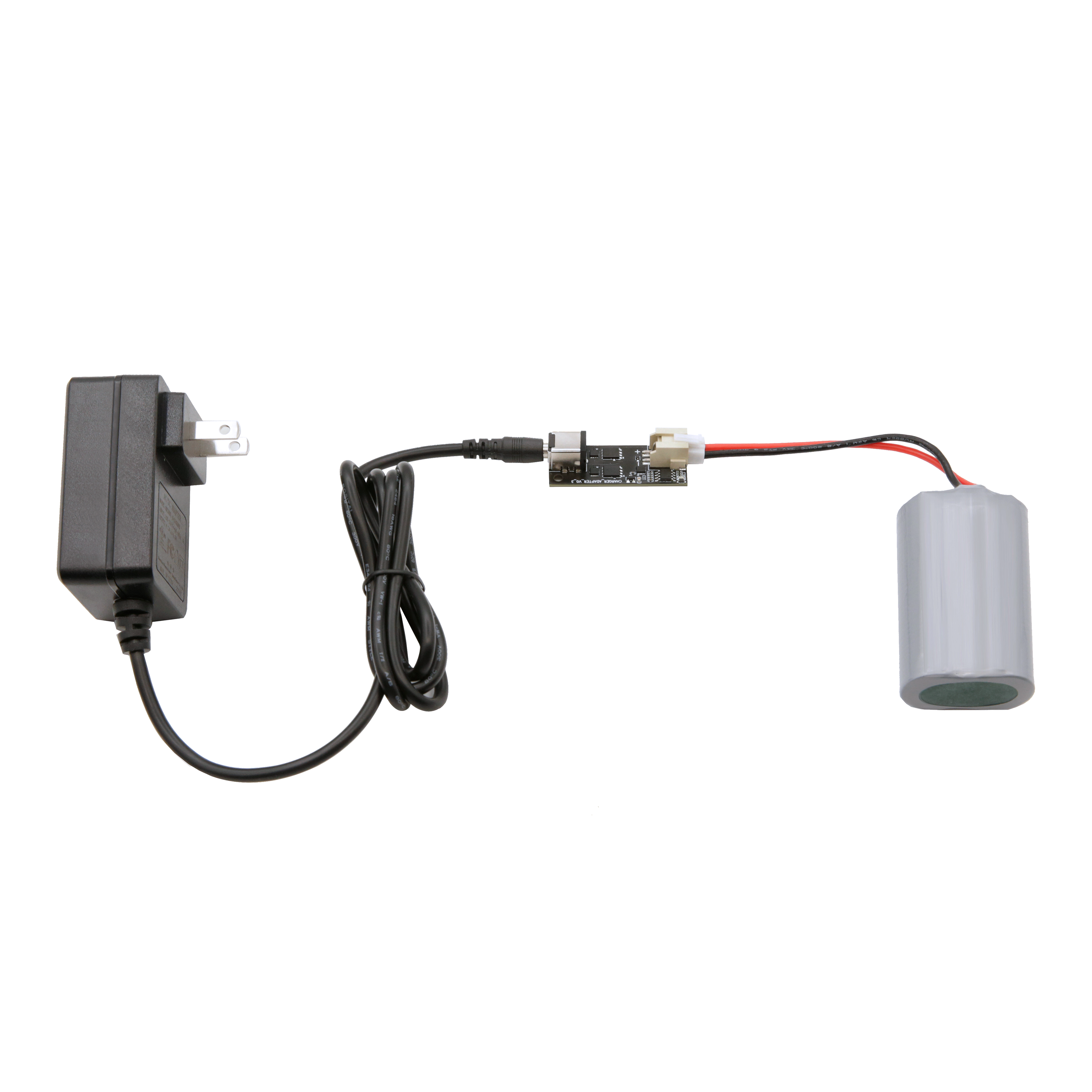
- 原文: https://www.yuque.com/makeblock-help-center-en/cyberpi/mbot2-battery-enhancement# Pack d'amélioration de batterie rechargeable LiPo mBot2
Le pack d'amélioration de batterie rechargeable LiPo mBot2 est un pack de batterie remplaçable pour la compétition MakeX Explorer. Ce pack a été conçu pour pallier les limites de la faible puissance de sortie et de la courte durée de vie de la batterie de mBot2 dans les scénarios à forte charge. Vous pouvez rapidement recharger la batterie avec plusieurs packs de batterie.
Spécifications
| Paramètres | Description |
|---|---|
| Numéro de modèle | HL 21700-2P |
| Tension nominale | 3,7 V |
| Capacité | 8000 mAh |
| Wattheure | 29,6 Wh |
Caractéristiques
- Remplaçable ; charge indépendante
- Capacité plus élevée, durée de vie de la batterie plus longue
- Puissance de sortie plus élevée pour les scénarios avec des exigences de charge plus élevées
Exemples
Adaptateur sans fil
Scénarios d'application
Votre appareil Makeblock ne peut pas se connecter à mBlock 5 directement via Bluetooth si :
- vous utilisez mBlock 5 sur un ordinateur de bureau sans adaptateur Bluetooth ; ou
- vous utilisez mBlock 5 sur un ordinateur portable équipé d'un adaptateur Bluetooth antérieur à Bluetooth 4.0 ou qui n'est pas compatible avec les appareils Makeblock en raison d'exceptions de pilote.
Pour résoudre ce problème, nous vous proposons l'adaptateur sans fil Makeblock. Avec celui-ci, vous pouvez connecter vos appareils Makeblock, tels que CyberPi, Codey Rocky, mBot de la version Bluetooth et mBot Ranger, à mBlock 5 sans fil, et ainsi déboguer les programmes de vos appareils en ligne et télécharger des programmes sur CyberPi, Halocode et Codey Rocky sans fil.

Description de l'indicateur
| Clignote lentement | En veille | Recherche de l'appareil avec lequel il a été apparié la dernière fois et effectue automatiquement l'appariement |
|---|---|---|
| Clignote rapidement | Appariement | Recherche d'un nouvel appareil à appairer avec lui |
| Allumé en permanence | Apparié |
Connexion matérielle
- Ouvrez le capuchon de protection.
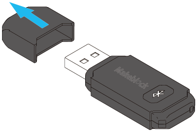
- Insérez l'adaptateur sans fil dans un port USB de votre ordinateur.
L'indicateur clignote lentement.
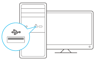
Appariement
Utilisez CyberPi comme exemple (dans cet exemple, Pocket Shield alimente CyberPi)
- Allumez CyberPi.

- Appuyez sur le bouton de l'adaptateur sans fil.
L'indicateur clignote rapidement. L'adaptateur sans fil entre dans l'état d'appariement.

- Placez CyberPi à proximité de l'adaptateur sans fil.
L'appariement est effectué automatiquement.
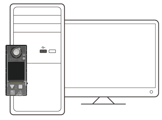 L'indicateur sur l'adaptateur sans fil reste allumé, indiquant que l'appariement est réussi.
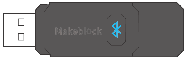
Connexion logicielle
Après qu'un appareil a été appairé avec succès avec l'adaptateur sans fil, vous devez le connecter à mBlock 5 avant de le programmer.
Dans cet exemple, CyberPi est l'appareil à programmer.
Cliquez sur Connecter, sélectionnez le port série utilisé par l'adaptateur sans fil dans la boîte de dialogue qui apparaît, et cliquez sur Connecter.
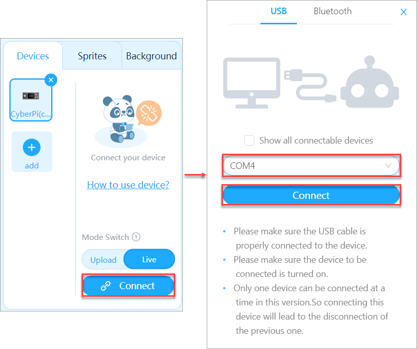
Un message s'affiche après la connexion de l'appareil, indiquant que la connexion est réussie.

Maintenant, vous pouvez commencer à programmer CyberPi sur mBlock 5 !
Pompe à eau
Avec les câbles de connexion spécifiés, la pompe à eau peut fonctionner avec Pocket Shield, mBot2 et les pilotes de moteur CC.
Lorsqu'elle est pilotée par Pocket Shield, mBot2 ou un pilote de moteur CC, la pompe à eau aspire de l'eau ou souffle de l'air pour contrôler le débit d'eau.
:::info Note :
- La pompe à eau doit être utilisée en combinaison avec un tube qui la supporte.
- La pompe à eau ne peut pas être utilisée dans l'eau. :::
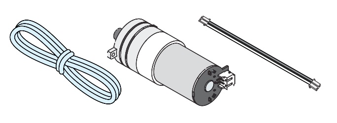
Description de la compatibilité
| Piloté par | Avec | Remarques |
|---|---|---|
| Port moteur CC — Pocket Shield |  | Note : Après avoir connecté la pompe à eau à Pocket Shield, mBot2 Shield ou mBuild DC motor driver, réglez la puissance de sortie du port, auquel la pompe à eau est connectée, sur une valeur positive lorsque vous la programmez sur mBlock 5. Sinon, la pompe à eau ne peut pas fonctionner correctement. |
| Port moteur CC — mBot2 Shield | ||
| Pilote de moteur CC mBuild |  | |
| Port pilote de moteur CC prenant en charge une tension de sortie de 5 V et un courant de crête de sortie supérieur à 1 A | Connectez-les par soudure ou utilisez un câble de connexion qui prend en charge le pilote |
- Texte original : https://www.yuque.com/makeblock-help-center-en/cyberpi/water_pump
Ventilateur
Avec les câbles de connexion spécifiés, le ventilateur peut fonctionner avec Pocket Shield, mBot2 et les pilotes de moteur CC.
Lorsqu'il est piloté par Pocket Shield, mBot2 ou un pilote de moteur CC, le ventilateur peut tourner dans le sens horaire ou antihoraire pour contrôler la puissance et la direction du vent.
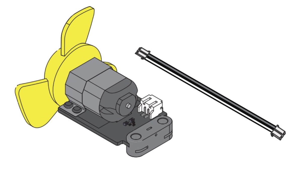
Description de la compatibilité
| Piloté par | Avec |
|---|---|
| Port moteur CC — Pocket Shield | 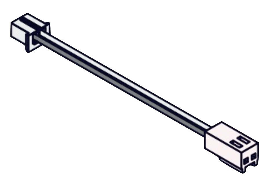 |
|
| Port moteur CC — mBot2 Shield | |
| Pilote de moteur CC mBuild | 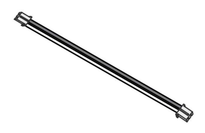 |
| Port pilote de moteur CC prenant en charge une tension de sortie de 5 V et un courant de crête de sortie supérieur à 1 A | Connectez-les par soudure ou utilisez un câble de connexion prenant en charge le pilote |
|
| Port pilote de moteur CC prenant en charge une tension de sortie de 5 V et un courant de crête de sortie supérieur à 1 A | Connectez-les par soudure ou utilisez un câble de connexion prenant en charge le pilote |
- Texte original : https://www.yuque.com/makeblock-help-center-en/cyberpi/fan_package
Servomoteur MS-1.5A
Le servomoteur MS-1.5A a été développé indépendamment par Makeblock. Ses dimensions sont similaires à celles des servomoteurs 9g courants.
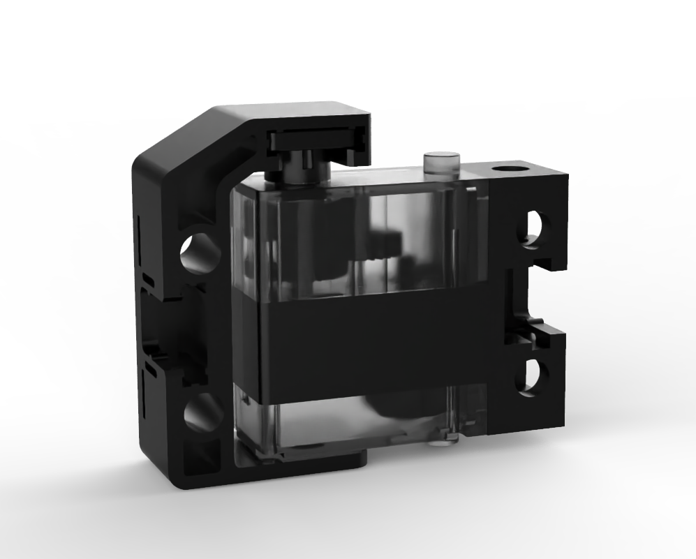
Comparaison des fonctionnalités
| Servomoteur MS-1.5A | Servomoteurs 9g plus anciens | |
|---|---|---|
| Hub de servomoteur monté avant livraison | Oui | Non |
| Prise en charge de l'assemblage rapide | Oui | Non |
| Compatible avec les pièces métalliques Makeblock et les blocs Lego | Oui | Oui, mais des supports d'adaptation sont nécessaires |
| Limite physique | Non (Les circuits ont été redessinés pour mieux protéger le servomoteur et ainsi garantir une durée de vie plus longue.) | Oui |
Exemple de connexion
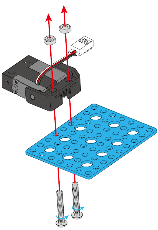
Dimensions (en millimètres)
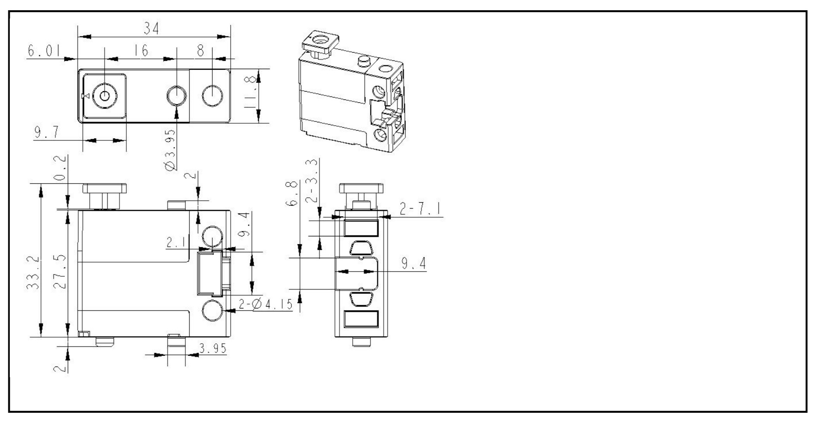
Spécifications
Grâce à la technologie la plus récente dans l'industrie des servomoteurs, le servomoteur MS-1.5 offre des performances considérablement améliorées. Les spécifications suivantes sont décrites ci-dessous.
Spécifications électriques (paramètres de performance)
| Élément | 4,6 V | 6,0 V |
|---|---|---|
| Vitesse de fonctionnement (sans charge) | 0,11 ± 0,01 sec/60° | 0,10 ± 0,01 sec/60° |
| Courant de fonctionnement (sans charge) | 270 mA ± 50 mA | 380 mA ± 50 mA |
| Couple de blocage (verrouillé) | 1,5 kg ± 0,30 kg·cm | 1,8 kg ± 0,30 kg·cm |
| Courant de blocage (verrouillé) | 1200 mA ± 50 mA | 1500 mA ± 70 mA |
| Courant d'arrêt (arrêté) | 4 mA ± 1 mA | 4 mA ± 1 mA |
| Durée de vie (sans charge) | > 180 mille fois | > 150 mille fois |
:::info Note : Le servomoteur fonctionne sans charge lorsque la valeur moyenne de l'élément 2 est définie. :::
Spécifications mécaniques
| Élément | Spécification |
|---|---|
| Dimensions globales | Voir "Dimensions." |
| Angle limite | Non |
| Poids | Selon le poids réel |
| Spécification du fil | JST 2,54 mm #30 PVC noir-blanc-rouge |
| Longueur du fil | 260 ± 5 mm (connecteurs non inclus) |
| Spécification de la corne | 20T |
| Type de corne | Sans objet |
| Jeu excessif | ≤ 1° |
Spécifications de contrôle
| Élément | Spécification |
|---|---|
| Système de contrôle | Sans objet |
| Type d'amplificateur | Sans objet |
| Course de fonctionnement | 180°± 5° (500 à 2500 µ sec) |
| Écart angulaire gauche-droite | ≤ 5° |
| Écart de centrage | ≤ 1° |
| Position neutre | Sans objet |
| Largeur de bande morte | Sans objet |
| Sens de rotation | Sens inverse des aiguilles d'une montre (500 à 2500 µ sec) |
| Plage de largeur d'impulsion | 500 à 2500 µ sec |
| Course maximale | Environ 180° (500 à 2500 µ sec) |
- Texte original : https://www.yuque.com/makeblock-help-center-en/cyberpi/ms-1.5a_servo
Servo 9g Micro (engrenage métallique)
Le servo 9g Micro (engrenage métallique) de Makeblock est un servo de haute qualité personnalisé par Makeblock. Il peut être livré assemblé ou non assemblé dans un pack, comprenant les quatre éléments suivants : servo 9g micro (engrenage métallique), corne de servo, vis et support de servo.
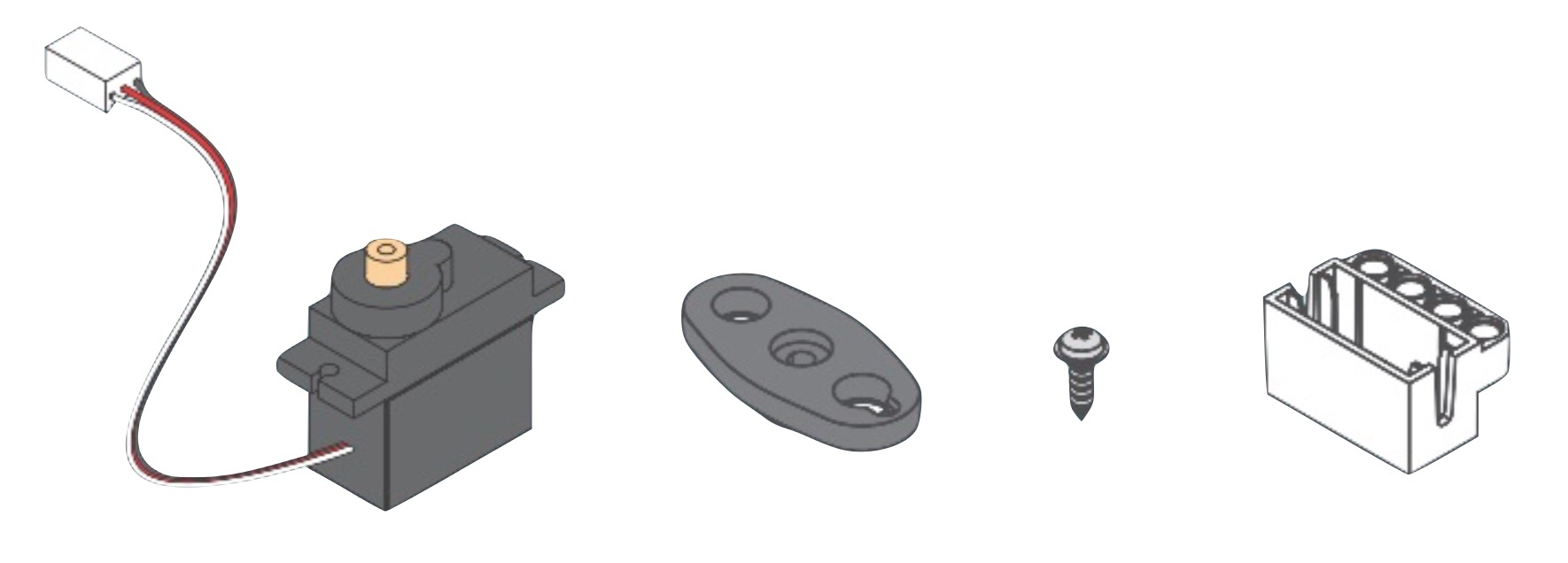
Dimensions
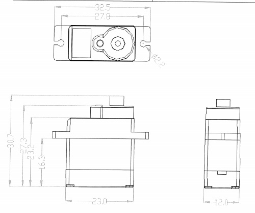
Spécifications
| Spécifications électriques | ||
|---|---|---|
| Élément | 4,8 V | 6,0 V |
| Vitesse de fonctionnement (sans charge) | 0,15±0,015 sec/60° | 0,13±0,015 sec/60° |
| Courant de fonctionnement (sans charge) | 80±35 mA | 90±35 mA |
| Charge maximale en fonctionnement | 1,0±0,05kg·cm | 1,1±0,1kg·cm |
| Couple de blocage (verrouillé) | 1,5±0,05kg·cm | 1,8±0,1kg·cm |
| Courant de blocage (verrouillé) | 680±40 mA | 750±50 mA |
| Courant d'arrêt (arrêté) | 6±1 mA | 6±1 mA |
| Dérive de température (à 25°C) | ≤5° | ≤7° |
| Spécifications mécaniques | ||
| Dimensions globales | Voir "Dimensions". | |
| Angle limite | 180°±10° | |
| Poids | 13,5±0,5g | |
| Section du fil de connexion | #28 PVC, noir-rouge-blanc, fiche : 2510-3P, blanc | |
| Longueur du fil de connexion | 260±5 mm | |
| Fente de l'engrenage de la corne | 40T | |
| Type de corne | Double bras | |
| Rapport de réduction | 1/324 | |
| Jeu excessif | ≤1° | |
| Vis | PM2×5 mm | |
| Spécifications de contrôle | ||
| Système de contrôle | Modification de la largeur d'impulsion | |
| Type d'amplificateur | Contrôleur analogique | |
| Course de fonctionnement | 180°±10° (600 à 2400 µ sec) | |
| Écart angulaire gauche et droite | ≤7° | |
| Écart de centrage | ≤1° | |
| Position neutre | 1500 µ sec | |
| Largeur de bande morte | ≤7 µ sec | |
| Sens de rotation | Sens inverse des aiguilles d'une montre (1500 à 2000 µ sec) | |
| Plage de largeur d'impulsion | 500 à 2500 µ sec | |
| Course maximale | Environ 190° (500 à 2500 µ sec) |
Moteur TT haute vitesse
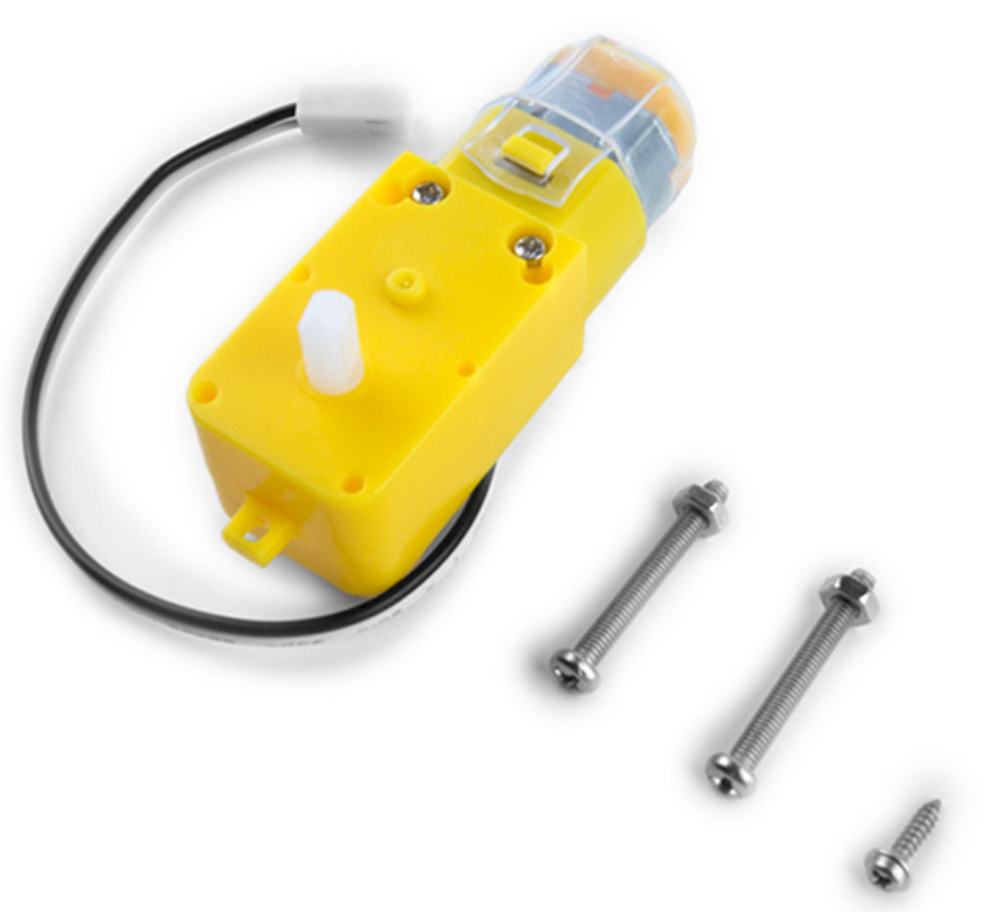
Le moteur TT haute vitesse Makeblock est un moteur à engrenages en plastique lancé par Makeblock. Vous pouvez utiliser des moteurs TT haute vitesse en combinaison avec des poulies de transmission en plastique Makeblock 62T ou 90T pour construire des mécanismes de roues dans les compétitions MakeX ou divers projets DIY.
Spécifications
| Élément | Description |
|---|---|
| Référence | M2010003000 |
| Tension nominale | 6V CC |
| Tension de fonctionnement | 4-8 V CC |
| Courant sans charge | ≤220mA |
| Courant avec charge nominale | ≤260mA |
| Vitesse de rotation sans charge | 15000 tr/min ±10% |
| Vitesse de rotation avec charge nominale | 310 tr/min ±10% |
| Rapport de démultiplication | 1 : 48 |
| Température et humidité de fonctionnement | -5℃ à + 40℃ ; 15%HR-90%HR |
| Température et humidité de stockage | -10℃ à +50℃ ; 15%HR-90%HR (sans condensation) |
Structure et dimensions
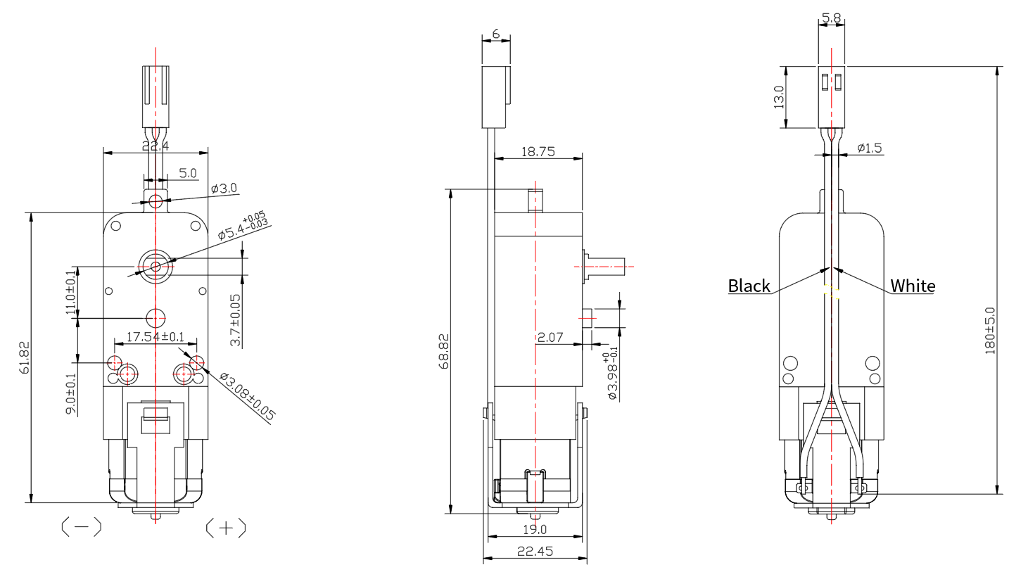
- Texte original : https://www.yuque.com/makeblock-help-center-en/cyberpi/high-speed-tt
Moteur TT à double arbre
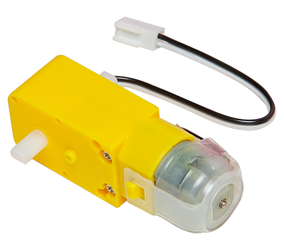 Le moteur TT à double arbre Makeblock est un moteur à engrenages en plastique à courant continu qui fournit une sortie à double arbre. Il prend en charge les ports de moteur CC des cartes d'extension de la série CyberPi et peut être utilisé dans divers projets DIY pour entraîner la rotation de toutes les pièces (comme les roues) connectées à ses arbres.
Spécifications
| Élément | Spécification |
|---|---|
| Tension nominale | CC 6 V |
| Vitesse sans charge | 200 tr/min ± 10 % |
| Rapport de démultiplication | 1:48 |
Caractéristiques
- Fournit une sortie à double arbre
- Prend en charge la rotation positive et négative
- Fournit un contrôle de haute précision
- Conçu avec une structure simple, promettant un entretien peu coûteux
Structure et dimensions
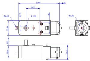
Exemple
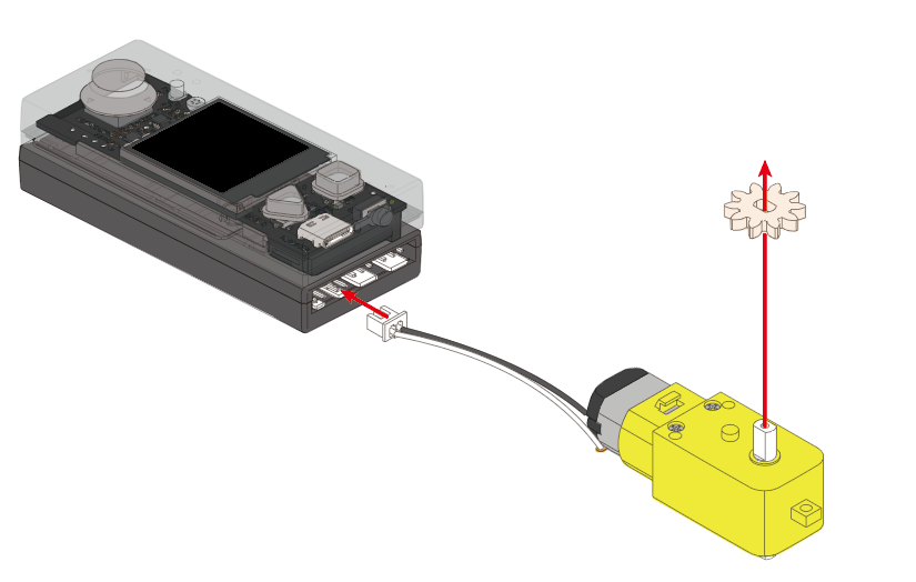
- Texte original : https://www.yuque.com/makeblock-help-center-en/cyberpi/tt-dual-shaft
Moteur à encodeur optique 180
Vue d'ensemble
Le moteur à encodeur optique 180 est équipé d'un encodeur optique qui permet un contrôle de haute précision. Avec deux trous filetés M4 sur chacun des trois côtés, il peut être facilement connecté à des pièces mécaniques Makeblock et ainsi être utilisé de manière flexible en combinaison avec diverses autres pièces. Le matériau personnalisé qu'il utilise réduit le bruit et garantit un couple de sortie élevé. Il prend en charge plusieurs pilotes de moteur et cartes de contrôle principales, tels qu'Orion, MegaPi, MegaPi Pro, Me Auriga et mBot2 Shield.
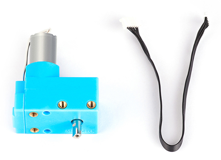
Performances électriques
| Tension d'alimentation | 5V | 7.4V |
|---|---|---|
| Plage de vitesse de rotation | 1-207 (tr/min) | 0-350 ± 5% (tr/min) |
| Précision de rotation | ≤ 5° | |
| Précision de détection | 1° | |
| Couple de rotation | 1 500 g·cm | Couple de démarrage : 5 000 g·cm |
| Couple nominal : 800 g·cm | ||
| Matériau de l'arbre de sortie | Métal |
Performances de contrôle
| Tournant | Tournant précis |
|---|---|
| Avançant droit | Écart : ≤2% |
| Fournir la commande pour avancer de XX mm | |
| Fonctionnant comme un servomoteur | Pris en charge |
| Précision de contrôle d'angle : ≤5° | |
| Fonctionnant comme une molette | Pris en charge |
| Précision de détection : 1° |
Spécifications mécaniques
- Rapport de réduction de l'engrenage : 39,6
- Longueur de l'arbre de sortie : 9 mm
- Texte original : https://www.yuque.com/makeblock-help-center-en/cyberpi/photoelectric-encoder-motor-180rpm
Bandeau LED (0,5 m et 1 m)
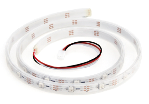
Vue d'ensemble
Le bandeau LED (adressable, étanche) est composé de plusieurs LED RVB adressables. Le bandeau LED RVB de 1 mètre comprend 30 LED RVB. En plus des caractéristiques de haute luminosité et de couleur complète, vous pouvez également contrôler la couleur et la luminosité de chaque LED RVB individuellement via la programmation.
Spécifications
- Longueur du câble : 1 m, 0,5 m
- Tension de fonctionnement : 5V CC
- Courant de fonctionnement : 1,8 A/m (courant maximum)
- Température de fonctionnement : -40 à +60°C
- Angle visible : >140°
- Durée de vie : > 50 000 heures
- Dimensions : 1000 x 13 x 3 mm (L x l x H), câble non inclus
Caractéristiques
- Fourniture de 256 niveaux de luminosité et de 16 777 216 couleurs pures
- Correspondance complète avec la bibliothèque Arduino pour faciliter la programmation
- Permettant de contrôler chaque LED individuellement
- Permettant de changer la forme du bandeau LED pour réaliser différents motifs lumineux
- Texte original : https://www.yuque.com/makeblock-help-center-en/cyberpi/led-strip
Mini bande LED et anneau
En raison du port physique et des protocoles de contrôle, la mini bande LED et l'anneau ne peuvent fonctionner correctement qu'avec le pilote LED mBuild. L'utilisation d'un pilote tiers pour piloter la mini bande LED ou l'anneau peut entraîner une déviation de couleur.
Bande LED
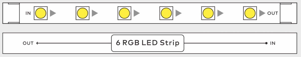
La bande LED peut être utilisée pour fabriquer une épée lumineuse ou des mots lumineux, ou pour créer une ambiance.

Lors de l'utilisation de la bande LED, connectez la prise IN au pilote LED ou à la prise OUT d'une autre LED, d'une bande LED ou d'un anneau LED.
La bande LED n'est pas étanche. Son utilisation dans l'eau peut l'endommager et ce type de dommage n'est pas couvert par la garantie.
Paramètre
- Dimensions : 8 mm × 112 mm
Anneau de 12 LED
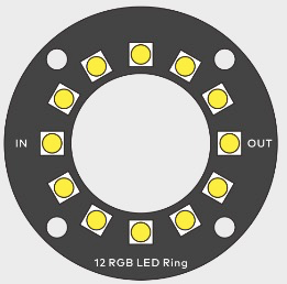
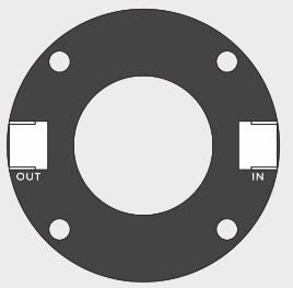
Lors de l'utilisation de l'anneau LED, connectez la prise IN au pilote LED ou à la prise OUT d'une autre LED, d'une bande LED ou d'un anneau LED.
L'anneau LED n'est pas étanche. Son utilisation dans l'eau peut l'endommager et ce type de dommage n'est pas couvert par la garantie.
Les emplacements des LED sur l'anneau de 12 LED sont définis de la même manière qu'une horloge, comme indiqué dans la figure suivante.
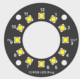
Paramètre
- Dimensions : diamètre de 45 mm
Description de la compatibilité
| Piloté par | Avec |
|---|---|
| Pilote LED mBuild | 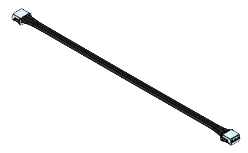 |
Adaptateur M4
L'adaptateur M4 est utilisé pour connecter des modules mBuild à d'autres pièces avec des trous M4 ou pour assembler des modules mBuild ensemble.
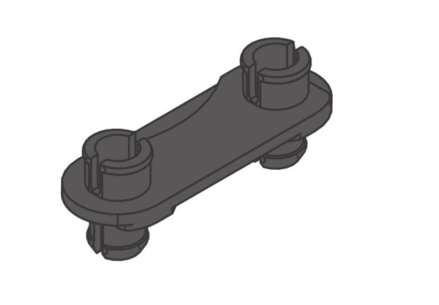
Exemples de connexion
Exemple 1
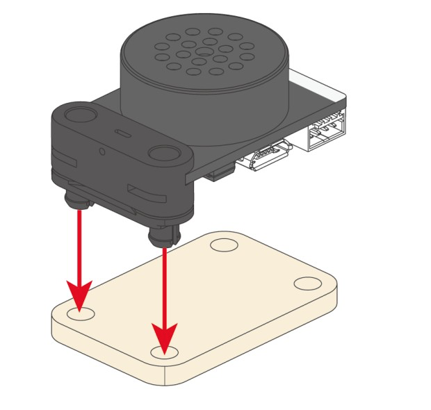
Exemple 2
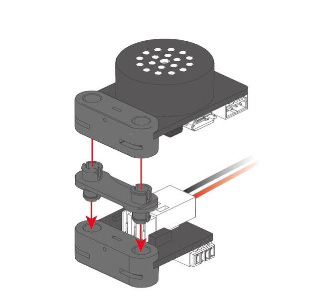
Câble universel 5V
Le câble universel 5V est utilisé pour connecter les modules mBuild ou connecter les modules mBuild à tout contrôleur principal compatible avec les modules mBuild. Actuellement, des câbles mBuild de 10 cm, 20 cm et 60 cm sont disponibles.
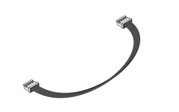
Si vous avez besoin d'un câble mBuild d'une autre longueur, vous pouvez combiner différents câbles avec le module d'extension.
Module d'extension
Le module d'extension peut être utilisé pour connecter deux câbles universels 5V afin de former un câble plus long.
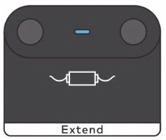
Exemple de connexion
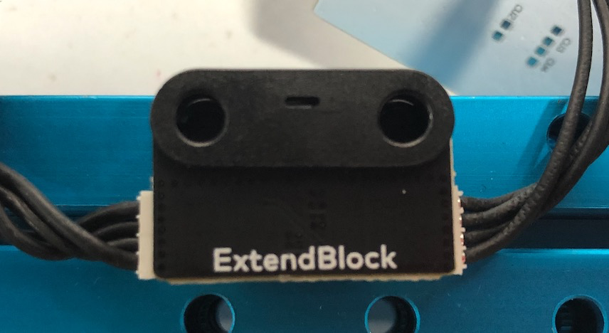
Doodle Boy (Détails de la fonction Doodle en détail)
1. Avant de commencer
- Les fonctions et programmes Doodle décrits dans cet article sont basés sur la version 006, assurez-vous que vos environnements matériels et logiciels sont de la version 006 ou supérieure.
- Ouvrez mBlock5, ajoutez CyberPi à la bibliothèque, sélectionnez Extension, et ajoutez l'extension Display+.
- Consultez le Guide d'exploitation de l'extension "Display+" pour CyberPi pour plus de détails.
2. Qu'est-ce que Doodle
Doodle est une fonction de l'extension Display+ qui émule les graphiques turtle en Python. C'est comme dessiner sur du papier avec un stylo. Dans mBlock5, nous pouvons utiliser les blocs Doodle pour contrôler l'épaisseur du trait, les coordonnées, et d'autres paramètres pour afficher des motifs personnalisés sur CyberPi.
3. Pour commencer
3.1 Commencer à dessiner
3.1.1 Ajouter Display+
Ajoutez CyberPi à la bibliothèque de périphériques et ajoutez l'extension "Display+", vous pouvez alors voir les catégories Sprites et Doodle comme illustré ci-dessous. Connectez CyberPi à l'ordinateur et vous pouvez commencer à programmer.
 _Remarque : Doodle ne peut être utilisé qu'en mode Téléversement
3.1.2. Entraînement avec exemple
Pour commencer à dessiner après avoir ajouté le bloc d'événement, vous devez également ajouter le bloc "Commencer à dessiner". Avant de commencer, vous pouvez définir l'épaisseur, la couleur et la position de départ du pinceau. Seulement en déplaçant le pinceau crée un chemin, tandis que la rotation ne laisse pas de trace sur l'écran. Après avoir fini de dessiner le motif, vous devez ajouter le bloc "Terminer le dessin" pour terminer le programme.
Voyons maintenant comment dessiner une ligne sur l'écran.
Pseudocode
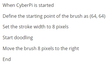
Blocs
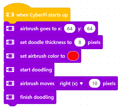
3.1.3 Téléverser le programme
Téléversez le programme sur l'appareil connecté et vous pouvez afficher le dessin sur l'écran.
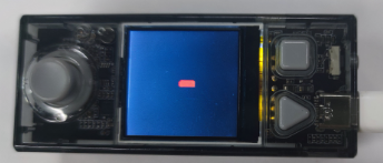
3.2 Utiliser le pinceau
Le pinceau est très important dans les blocs Doodle. Il fonctionne comme un pinceau pour dessiner des motifs sur l'écran. Vous pouvez utiliser les blocs Doodle dans mBlock5 pour déplacer, faire pivoter et positionner le pinceau, et vous pouvez utiliser des fonctions et des variables pour créer des motifs graphiques plus complexes.
Fonctions du pinceau
Vous pouvez utiliser les blocs pour ajuster la direction et les coordonnées du pinceau et pour définir le nombre de pixels qu'il se déplace. Pour dessiner des graphiques avec Doodle, vous devez utiliser les blocs pinceau.
Blocs du pinceau
| Fonction | Blocs | Description |
|---|---|---|
| Couleur | 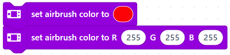 | Vous pouvez définir la couleur du pinceau de deux manières : |
- Sélectionnez la couleur via la palette de couleurs.
- Définissez les valeurs RGB, de 0 à 255, c'est-à-dire de la lumière minimale à la lumière maximale. |
| Mouvement linéaire |
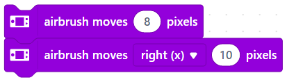 |
|
Le pinceau se déplace en pixels pour dessiner une ligne droite. La direction est par défaut vers la droite.
|
| Mouvement de rotation |  |
Vous pouvez définir le rayon et l'angle pour dessiner des cercles ou des arcs de tailles différentes.
|
Vous pouvez définir le rayon et l'angle pour dessiner des cercles ou des arcs de tailles différentes.
|
| Angle de rotation | 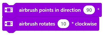 | Vous pouvez ajuster l'angle du pinceau de deux manières :
- Cliquez sur la boîte de saisie pour révéler le cadran et faites glisser la flèche pour ajuster l'angle. Ici, le pinceau pointe dans la direction 90°, parallèle à la direction positive de l'axe X.
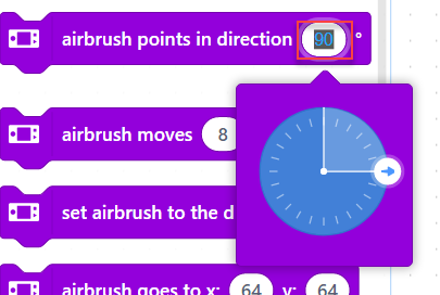
- Entrez un degré spécifié par lequel le pinceau tourne dans le sens des aiguilles d'une montre. La flèche du pinceau fait face à droite par défaut et change après chaque ajustement d'angle. La direction de l'angle que vous voyez est celle après le dernier ajustement. |
| Positionnement |
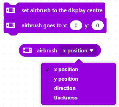 | Vous pouvez définir le point de départ du pinceau de trois manières :
 - Réglez-le au centre de l'écran
- Déplacez-le aux coordonnées spécifiées. Ici (0,0) est sur le sommet de l'angle droit dans le coin supérieur gauche de l'écran.
- Ajustez les paramètres. |
4. Aide aux blocs
Si vous avez des questions lors de l'utilisation du bloc, vous pouvez cliquer avec le bouton droit sur le bloc et sélectionner Aide dans le menu.
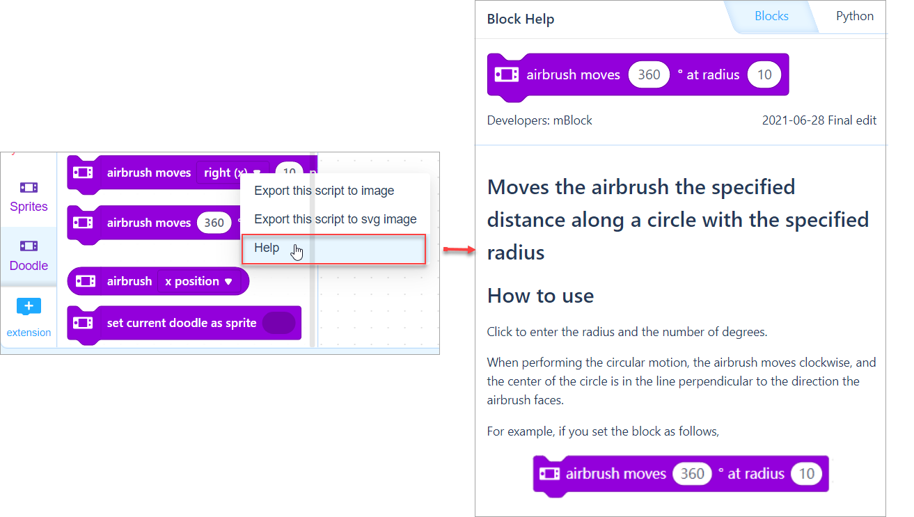 Alternativement, vous pouvez consulter l'aide aux blocs pour Display+.
5. Programmes d'exemple
Balle Doodle
Battement de cœur ECG
Course de balle de blocage
Suivi de ligne avec Kp
Comment le capteur quad RGB réagit-il lorsqu'il détecte une ligne?
Les quatre indicateurs du capteur quad RGB vous aident à savoir rapidement ce que le capteur a détecté : lorsque l'arrière-plan est détecté, l'indicateur s'allume ; sinon, l'indicateur ne s'allume pas.
Par défaut, le capteur quad RGB identifie les couleurs plus claires comme des arrière-plans et les couleurs plus sombres comme des lignes.
Comment le capteur différencie-t-il une ligne d'un arrière-plan?
Le capteur quad RGB possède 4 sondes capables de détecter l'intensité lumineuse. Elles fonctionnent en détectant activement l'intensité de la lumière réfléchie après que la lumière de remplissage ait éclairé l'objet.
Le capteur peut déduire la valeur de gris de l'objet. Plus la valeur de gris est élevée, plus l'objet est lumineux, sinon il est plus sombre.
Pour distinguer la ligne de l'arrière-plan, nous devons également donner au capteur une valeur de seuil, indiquant au capteur que les couleurs au-dessus ou en dessous de ce seuil sont des couleurs d'arrière-plan, sinon ce sont des lignes. De cette manière, le capteur peut distinguer les arrière-plans des lignes.
Par défaut, nous définissons une valeur de seuil uniforme pour le capteur quad RGB, afin que vous puissiez l'utiliser dès la sortie de la boîte.
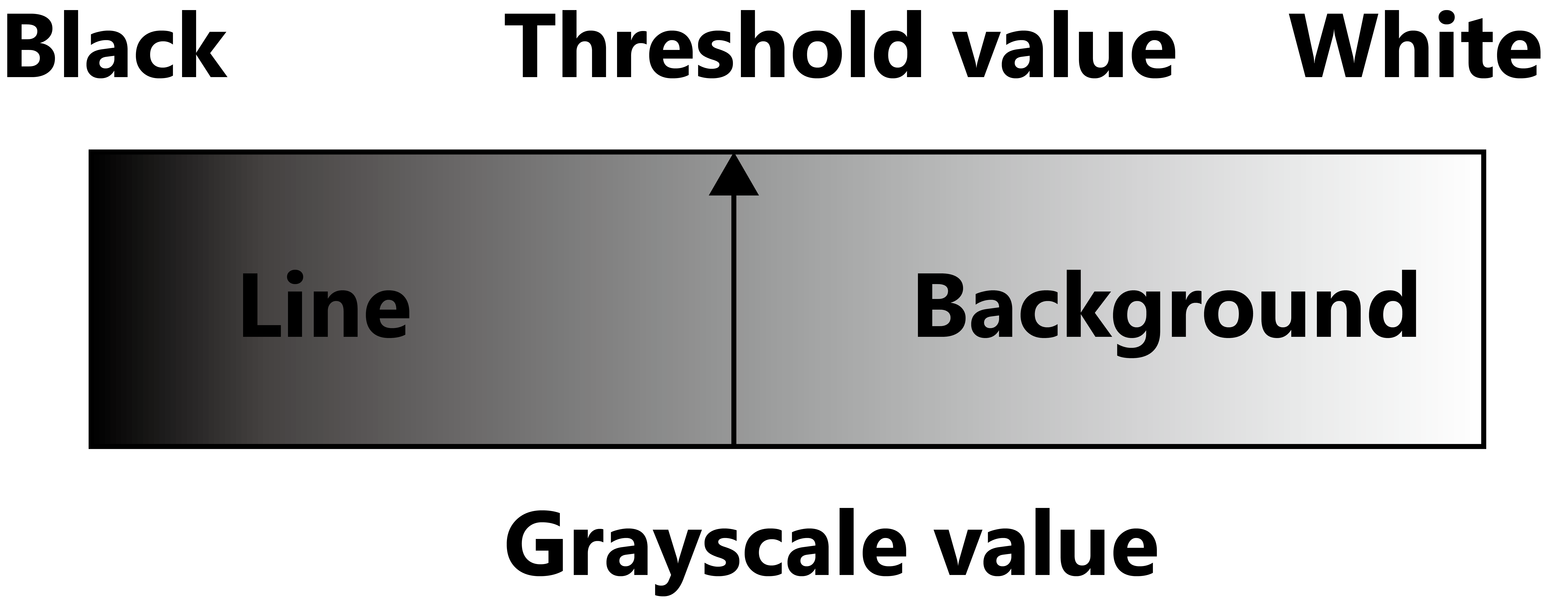
Valeur de seuil par défaut
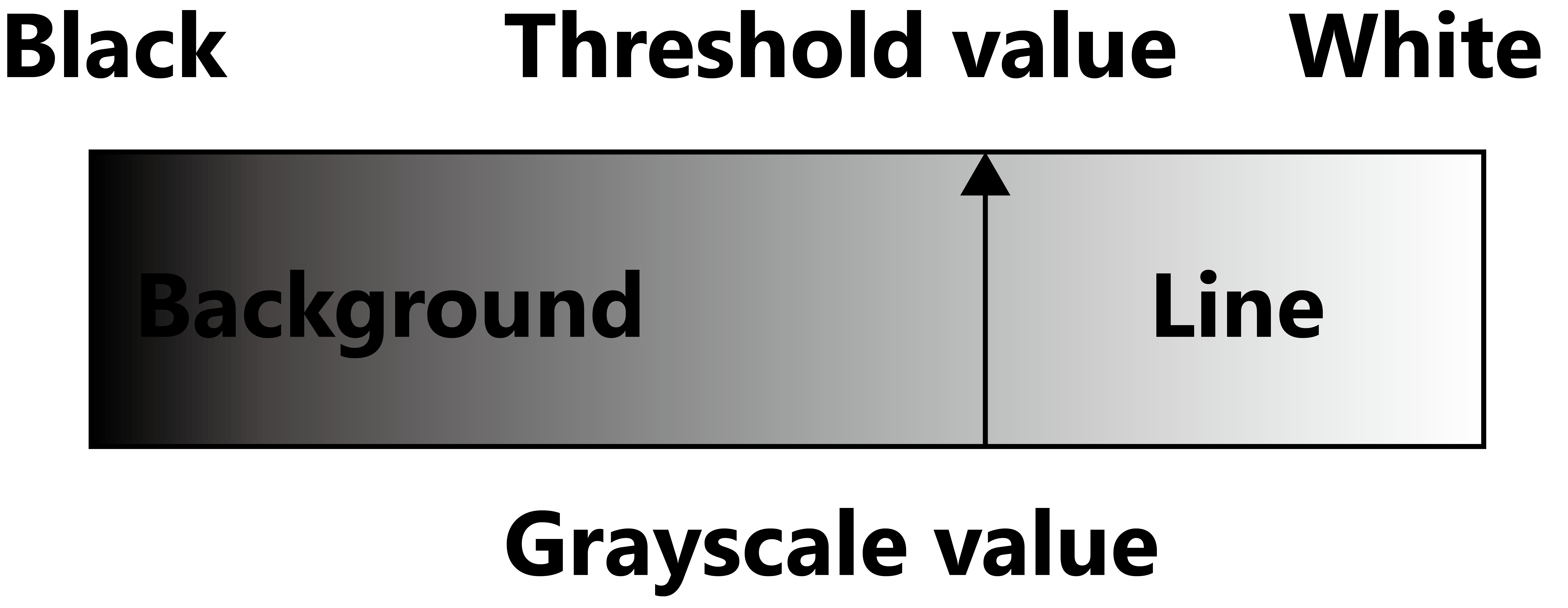 Vous pouvez également définir une nouvelle valeur de seuil ou définir des couleurs sombres comme arrière-plans en apprenant.
Permettez au capteur d'apprendre une nouvelle ligne et un nouvel arrière-plan avec le bouton d'apprentissage
Dans les concours, nous utilisons souvent des cartes de suivi de ligne avec des lignes blanches sur un fond noir (ce qui rend la carte plus durable) ou d'autres combinaisons de couleurs d'arrière-plan et de lignes. Dans ces cas, nous devons utiliser la fonction de calibrage du capteur quad RGB.
La fonction apprentissage permet au capteur quad RGB de trouver la couleur de la lumière de remplissage et la valeur de seuil qui correspondent le mieux à la lumière ambiante actuelle, à la couleur d'arrière-plan et à la couleur de la ligne. Les méthodes sont les suivantes.
-
Double clic : déclenche l'apprentissage du suivi de ligne.
- Placez les deux sondes du capteur sur l'arrière-plan de la carte de suivi de ligne, et double-cliquez sur le bouton apprentissage.
- Lorsque vous voyez les deux indicateurs de suivi de ligne clignoter rapidement, à une hauteur fixe sur l'arrière-plan, secouez le capteur jusqu'à ce que les indicateurs arrêtent de clignoter rapidement (cela prendra environ 2,5 secondes).
- Les paramètres d'apprentissage seront automatiquement enregistrés. Si l'apprentissage échoue, les deux indicateurs de suivi de ligne passeront en clignotement lent et vous devrez réapprendre.
-
Appui long : basculez la couleur de la lumière de remplissage (généralement, vous n'avez pas besoin de basculer la couleur de la lumière de remplissage, elle sera définie automatiquement après un apprentissage réussi)
Écrire un programme simple de suivi de ligne
Commençons par regarder un programme simple de suivi de ligne.
Répéter
Si (la tête du mBot est alignée avec la ligne)
	Le mBot avance tout droit
Si (la tête du mBot est sur le côté gauche de la ligne).
	Le mBot tourne à droite à un angle
Si (la tête du mBot est sur le côté droit de la ligne).
	Le mBot tourne à gauche à un angle
En anglais
Repeat
	If (the head of the mBot is aligned with the line)
		The mBot goes straight ahead
	If (the head of the mBot is on the left side of the line).
		The mBot turns right at an angle
	If (the head of the mBot is on the right side of the line).
		The mBot turns left at an angle
Notez que ce programme ne discute pas encore de ce qu'il faut faire lorsque le mBot s'écarte de la ligne, alors permettez-moi d'imbriquer une instruction if-else pour résoudre ce problème.
Répéter
	Si
		Si (la tête du mBot est alignée avec la ligne)
		Le mBot avance tout droit
	Si (la tête du mBot est sur le côté gauche de la ligne).
		Le mBot tourne à droite à un angle
	Si (la tête du mBot est sur le côté droit de la ligne).
		Le mBot tourne à gauche à un angle
	Sinon
	Le mBot s'arrête
Il existe également des blocs pour diriger le mBot.
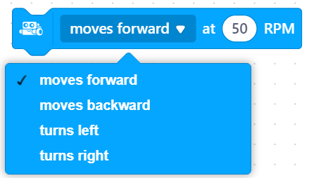
Lire la position du mBot par rapport à la ligne à partir du statut de suivi de ligne
Avec la bonne définition des couleurs de ligne et d'arrière-plan, nous pouvons mieux comprendre le statut de suivi de ligne du capteur quad RGB.
Le capteur quad RGB se compose de nombres binaires de 4 bits allant de 0000 à 1111, correspondant aux nombres décimaux de 0 à 15. Les nombres binaires, de haut en bas, correspondent aux résultats de la détection de ligne et d'arrière-plan détectés par les capteurs L2, L1, R1, R2. Lorsque le capteur détecte une couleur d'arrière-plan, le bit correspondant lit 1, sinon, il lit 0. Voici un résumé du statut de lecture et des résultats de détection des capteurs.
| Statut de suivi de ligne (Décimal) | Statut de suivi de ligne (Binaire) | État L2 | État L1 | État R1 | État R2 | Illustration (lignes noires sur fond blanc) |
|---|---|---|---|---|---|---|
| 0 | 0000 | Ligne | Ligne | Ligne | Ligne |  |
| 1 | 0001 | Ligne | Ligne | Ligne | Arrière-plan |  |
| 2 | 0010 | Ligne | Ligne | Arrière-plan | Ligne |  |
| 3 | 0011 | Ligne | Ligne | Arrière-plan | Arrière-plan |  |
| 4 | 0100 | Ligne | Arrière-plan | Ligne | Ligne |  |
| 5 | 0101 | Ligne | Arrière-plan | Ligne | Arrière-plan |  |
| 6 | 0110 | Ligne | Arrière-plan | Arrière-plan | Ligne |  |
| 7 | 0111 | Ligne | Arrière-plan | Arrière-plan | Arrière-plan |  |
| 8 | 1000 | Arrière-plan | Ligne | Ligne | Ligne |  |
| 9 | 1001 | Arrière-plan | Ligne | Ligne | Arrière-plan |  |
| 10 | 1010 | Arrière-plan | Ligne | Arrière-plan | Ligne |  |
| 11 | 1011 | Arrière-plan | Ligne | Arrière-plan | Arrière-plan |  |
| 12 | 1100 | Arrière-plan | Arrière-plan | Ligne | Ligne |  |
| 13 | 1101 | Arrière-plan | Arrière-plan | Ligne | Arrière-plan |  |
| 14 | 1110 | Arrière-plan | Arrière-plan | Arrière-plan | Ligne |  |
| 15 | 1111 | Arrière-plan | Arrière-plan | Arrière-plan | Arrière-plan |  |
Lire la position du mBot par rapport à la ligne à partir de la valeur de déviation
Sur la base de la lecture de la valeur de gris des sondes du capteur L1 et R1, ainsi que de la définition des couleurs de ligne et d'arrière-plan par le capteur, le capteur est capable de calculer la déviation du mBot par rapport au centre de la ligne.
- Lorsque le capteur est du côté gauche de la ligne, la valeur de déviation < 0 ; dans ce cas, la tête du mBot doit tourner à droite, et les roues gauche du mBot doivent accélérer ; les roues droite doivent décélérer.
- Lorsque le capteur est du côté droit de la ligne, la valeur de déviation > 0 ; dans ce cas, la tête du mBot doit tourner à gauche, et les roues gauche du mBot doivent décélérer ; les roues droite doivent accélérer.
En combinant le réglage de la vitesse des moteurs du châssis mBot et la définition de la vitesse avant du moteur encodeur (dans le sens antihoraire est la vitesse avant), on peut voir que si le mBot doit avancer tout droit à une vitesse de base, les roues gauche doivent tourner dans le sens antihoraire ; les roues droite doivent tourner dans le sens horaire. Nous pouvons définir la vitesse du moteur encodeur comme suit : Roue gauche : vitesse de base, roue droite : -1*vitesse de base.
Par conséquent, la valeur de déviation peut être utilisée pour augmenter ou diminuer dynamiquement la vitesse des moteurs pour un suivi de ligne plus fluide.
Lorsque le capteur est du côté gauche de la ligne, la valeur de déviation < 0 ; dans ce cas, la tête du mBot doit tourner à droite, et les roues gauche du mBot doivent accélérer ; vitesse gauche = vitesse de base + valeur absolue * valeur de déviation = vitesse de base - valeur de déviation les roues droite doivent décélérer, vitesse droite = -1*(vitesse de base-valeur absolue(valeur de déviation))=-1*(vitesse de base+valeur de déviation)
Lorsque le capteur est du côté droit de la ligne, la valeur de déviation > 0 ; dans ce cas, la tête du mBot doit tourner à gauche, et les roues gauche du mBot doivent décélérer ; vitesse gauche = vitesse de base - valeur absolue * valeur de déviation = vitesse de base - valeur de déviation Les roues droite doivent accélérer, vitesse droite = -1*(vitesse de base+valeur absolue(valeur de déviation))=-1*(vitesse de base+valeur de déviation)
Pour résumer, nous pouvons obtenir la formule pour régler la vitesse des moteurs lors du suivi de ligne. vitesse gauche = vitesse de base - valeur de décalage vitesse droite =-1*(vitesse de base+décalage)
La vitesse de base est la vitesse de base du mBot suivant la ligne, et la valeur de déviation est la position du mBot par rapport à la ligne telle qu'inférée par le capteur de suivi de ligne.
Appliquer le concept de Kp
Bien que très rudimentaire, avec vitesse gauche=vitesse de base-valeur de déviation vitesse droite =-1(vitesse de base+valeur de déviation)* un contrôle en boucle fermée simple est mis en œuvre. Le RPM du moteur contrôle le mouvement du mBot, qui change sa position par rapport à la ligne. La position du mBot est détectée par le capteur quad RGB et calculée comme une valeur de déviation, et finalement nous utilisons la valeur de déviation pour définir un nouveau RPM de moteur pour le mBot.
Cependant, si nous utilisons la formule ci-dessus directement, nous pouvons facilement constater que les résultats réels ne sont pas satisfaisants. Nous savons que nous devons tourner à droite lorsque le mBot s'écarte à gauche, mais s'il ne tourne pas à droite ou s'il tourne trop loin, il ne pourra pas obtenir un meilleur résultat de suivi de ligne. Nous avons besoin d'un paramètre pour contrôler l'effet de la valeur de déviation sur le degré de virage. C'est là que le contrôleur proportionnel "Kp" intervient.
Dans l'algorithme de contrôle de robot plus complexe, les ingénieurs introduisent souvent un contrôleur proportionnel intégrateur et différentiel pour lisser l'ensemble du processus de contrôle. Cependant, cela est beaucoup plus complexe et nous n'allons pas l'approfondir ici.
Avec le concept de Kp, nous pouvons réécrire la formule originale comme suit vitesse gauche=vitesse de base-Kp*valeur de déviation vitesse droite =-1(vitesse de base+Kp*valeur de déviation)*
En général, plus la vitesse de base est grande, plus la valeur de Kp devra être grande pour éviter que le mBot ne tourne pas à temps, tandis que plus la vitesse de base est petite, plus la valeur de Kp devra être petite pour éviter une surrotation. Il n'y a pas de réglage de Kp fixe, mais vous devez choisir la valeur en fonction de votre situation et de vos besoins.
Introductionto the 2024 MakeX Inspire Smart Logistics Arena and Frame
Introductionto the 2024 MakeX Starter All-Core Journey Educational Competition Kit
GettingStarted with the 2024 MakeX Starter All-Core Journey Educational Competition Kit
Introductionto the 2024 MakeX Starter Upgrade Kit
GettingStarted with the 2024 MakeX Starter Upgrade Kit
Introductionto the 2024 MakeX Starter All-Core Journey Arena and Frame
Introductionto the 2024 MakeX Starter Arena Upgrade Kit - Zero Carbon
Introductionto the 2024 MakeX Explorer Digital Pioneer Educational Competition Kit
GettingStarted with the 2024 MakeX Explorer Digital Pioneer Educational Competition Kit
Introductionto the 2024 MakeX Explorer Upgrade Kit
GettingStarted with the 2024 MakeX Explorer Upgrade Kit
Introductionto the 2024 MakeX Explorer Digital Pioneer Arena and Frame
Introductionto the 2024 MakeX Explorer Arena Upgrade Kit - Eco-Pioneer
Introductionto the 2024 MakeX Challenge Ultimate Winner Educational Competition Kit
GettingStarted with the 2024 MakeX Challenge Ultimate Winner Educational Competition Kit
Introductionto the 2024 MakeX Challenge Upgrade Kit
GettingStarted with the 2024 MakeX Challenge Upgrade Kit
Introductionto the 2024 MakeX Challenge Ultimate Winner Arena and Frame
Introductionto the 2024 MakeX Challenge Arena Upgrade Kit - Energy Innovator
Introductionto the CyberPi Educational Competition Kit
GettingStarted with the CyberPi Educational Competition Kit
Getting started with the CyberPi Educational Competition Kit
1. Foreword
Thank you for choosing CyberPi Educational Competition Kit, an upgraded version of CyberPi AI & IoT Innovation kit. If you are using this kit for the first time, we recommend that you read this guide carefully to get the most out of it.
2. Unpacking and check
Make sure the following parts are included in the kit. If there is any missing part, contact our after-sales service or distributors.

3. Learn about the main components
This kit contains a variety of electronic and structural parts that you can get to know as you go through the course.
You can also familiarize yourself with these parts before you start the course to quickly get into the swing of things.
| Name | Quantity | Documentation |
|---|---|---|
| CyberPi | 1 | For technical information on CyberPi, see makeblock.com/en/docs/cyberpi/cyberpi |
| For the operation guide of CyberPi, see | ||
| makeblock.com/en/docs/cyberpi/cyberpi-start | ||
| Pocket Shield | 1 | For technical information on Pocket Shield, see |
| makeblock.com/en/docs/cyberpi/pocket-shield | ||
| Servo MS-1.5A | 1 | For technical information on Servo MS-1.5A, see http://docs.makeblock.com/diy-platform/en/electronic-modules/motors/meds15-servo-motor.html |
| Ranging Sensor | 1 | For technical information on Ranging Sensor, see |
| makeblock.com/en/docs/cyberpi/ranging_sensor | ||
| Multi-touch Sensor | 1 | For technical information on Multi-touch Sensor, see |
| makeblock.com/en/docs/cyberpi/multi_touch | ||
| Angle sensor | 1 | For technical information on Angle sensor, see |
| makeblock.com/en/docs/cyberpi/angle_sensor | ||
| Fan | 1 | For technical information on Fan, see |
| makeblock.com/en/docs/cyberpi/fan-package | ||
| Dual Shaft TT Motor | 1 | For technical information on Dual Shaft TT Motor, see |
| makeblock.com/en/docs/cyberpi/tt-dual-shaft | ||
| LED Strip(1m) | 1 | For technical information on LED Strip(1m), see |
| makeblock.com/en/docs/cyberpi/led-strip |
4. Courses
Documents are on the way. Stay tuned!
5. Explore beyond
CyberPi has a wide range of peripherals to bring your ideas to life. Contact us (https://education.makeblock.com/contact-us) if you want to take them home.
6. About the competition
MakeX is an international robotics competition and education platform that promotes multidisciplinary learning within the fields of science and technology. It aims at building a world where STEAM education is highly appreciated and where young people are passionate about innovation by engaging them in exciting Robotics Competition, STEAM Carnival, Tech Event, Educational Conference etc.
MakeX Spark is an innovation competition program for young people aged 6-13.
The competition includes online and onsite competition formats. Contestants are encouraged to use a variety of materials to design and build their projects. Through project-based learning, contestants boost their imagination and creativity, and combined with critical thinking and research of a real-world issue, contestants are improving their cross-disciplinary problem-solving skills. Also, the contestants' skills in expression, collaboration, and cooperation can be enhanced through project demonstration.

To view information about registration, entry requirements and available competitions, visit www.makex.cc/en
Or contact us by email: makex_overseas@makeblock.com (overseas) makex@makeblock.com (China)
7. Online support
If you encounter any product quality issues or find any parts missing when you open the package, contact us for after-sales services at support@makeblock.com
We would also appreciated it if you could give us your feedback on the product at cyber.list@makeblock.com
8. More information
CyberPi Series User Manual makeblock.com/en/docs/cyberpi CyberPi Operation Guide makeblock.com/en/docs/cyberpi/cyberpi-start mBot2 Operation Guide makeblock.com/en/docs/cyberpi/mbot2-start Python API Documentation for CyberPi makeblock.com/en/docs/mcode/cyberpi-api mBlock 5 Online Help makeblock.com/en/docs/mblock-5 mBlock-Python Editor Online Help makeblock.com/en/docs/mcode 2022 MakeX Educational Competition Kits makeblock.com/en/docs/cyberpi/22makex
2021-2022 MakeX Inspire Fruit Wonderland Arena Kit
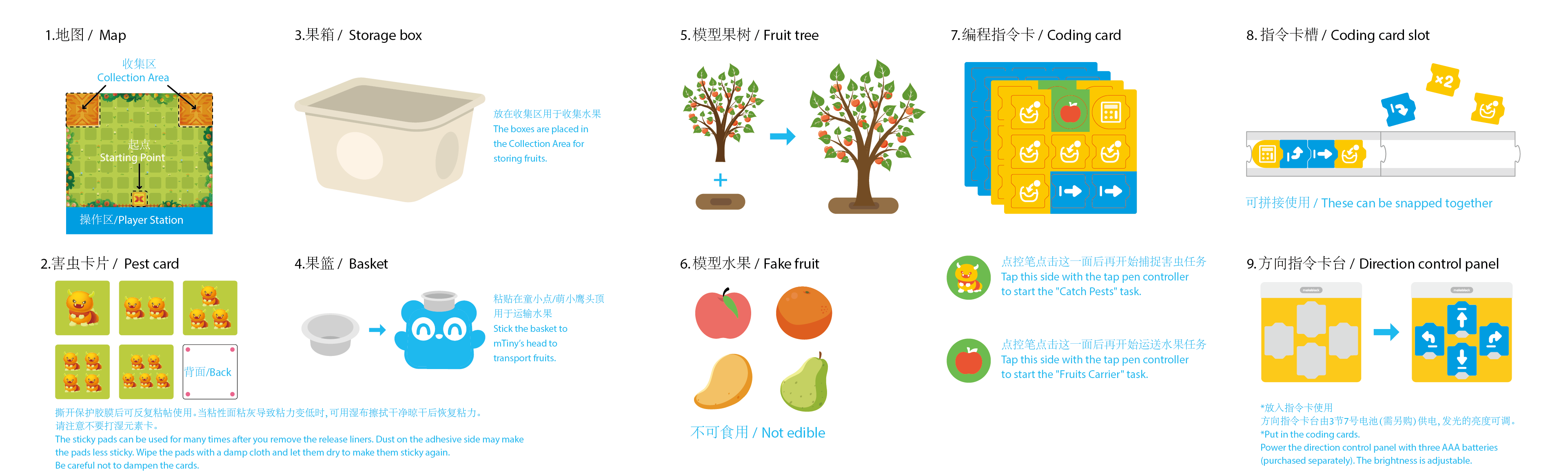
1. Basic information
2021-2022 MakeX Inspire Fruit Wonderland Arena Kit
| Name | 2021-2022 MakeX Inspire Fruit Wonderland Arena Kit |
|---|---|
| SKU | P1090032 |
| EAN | 6928819513082 |
| Package type | Paper box |
| Package size | 390mm178mm278mm |
| 861mm*1107mm(Map) | |
| Gross weight (including packaging) | 1671.5g |
| Others | Remote control and battery not included |
2. Overview
2021-2022 MakeX Inspire Fruit Wonderland Arena Kit is recommended for activities of young children. You need to use it in combination with the mTiny coding kit.
3. Parts list
Make sure the following parts are included in the kit. If there is any missing part, contact our after-sales service or distributors.
| Name | Quantity |
|---|---|
| Map | 1 |
| Element card pack | 1 |
| Fruit tree model | 4 |
| Apple model | 3 |
| Orange model | 3 |
| Pear model | 3 |
| Mango model | 3 |
| Basket | 2 |
| PU traceless Nano tape 30mm*2mm | 2 |
| Storage box | 2 |
| Coding card pack | 1 |
| Coding card slot | 4 |
| Lighting board for reading | 1 |
| Direction control panel | 1 |
| Silicone spacer block ∅15*5mm | 4 |
| Direction control panel sticker | 1 |
| User Guide (in Chinese & English) | 1 |
4. Assembly instruction
After checking the number of parts, refer to the following document to assemble the 2022 MakeX Inspire Arena. MakeX_Inspire童心果园场地套装_中英说明书_V1.0_D1.1.1_KD010404000_Preview(1) (1)(1).pdf
5. About the activity
MakeX is an international robotics competition and education platform that promotes multidisciplinary learning within the fields of science and technology. It aims at building a world where STEAM education is highly appreciated and where young people are passionate about innovation by engaging them in exciting Robotics competitions, STEAM carnivals, tech events, educational conferences, etc.
MakeX Inspire is a STEAM activity for kids aged 4 to 7 years. It aims to develop kids' mathematical and scientific thinking through the tap-to-read robotic interaction; inspire kids' interests in programming, develop their multiple intelligence and independent thinking, and build their self-confidence through diverse scenarios.
To view information about registration, entry requirements, and available competitions, visit www.makex.cc/en
Or contact us by email: makex_overseas@makeblock.com (overseas) makex@makeblock.com (China)
6. More information
mBlock 5 Online Help: makeblock.com/en/docs/mblock-5 mTiny User Guide: makeblock.com/en/docs/mtiny Introduction to the 2022 MakeX competitions and kits: makeblock.com/en/docs/cyberpi/22makex
GettingStarted with the 2022 MakeX Starter Educational Competition Kit
Getting Started with the 2022 MakeX Starter Add-on Pack
1. Foreword
Thank you for choosing the 2022 MakeX Starter Educational Competition Kit. The kit also comes with courses for the 2022 MakeX Starter Zero Carbon Initiative or for classroom use.
If you are using this kit for the first time, we recommend that you read these instructions carefully to get the most out of it.
2. Unpacking and check
Make sure the following parts are included in the kit. If there is any missing part, contact our after-sales service or distributors.
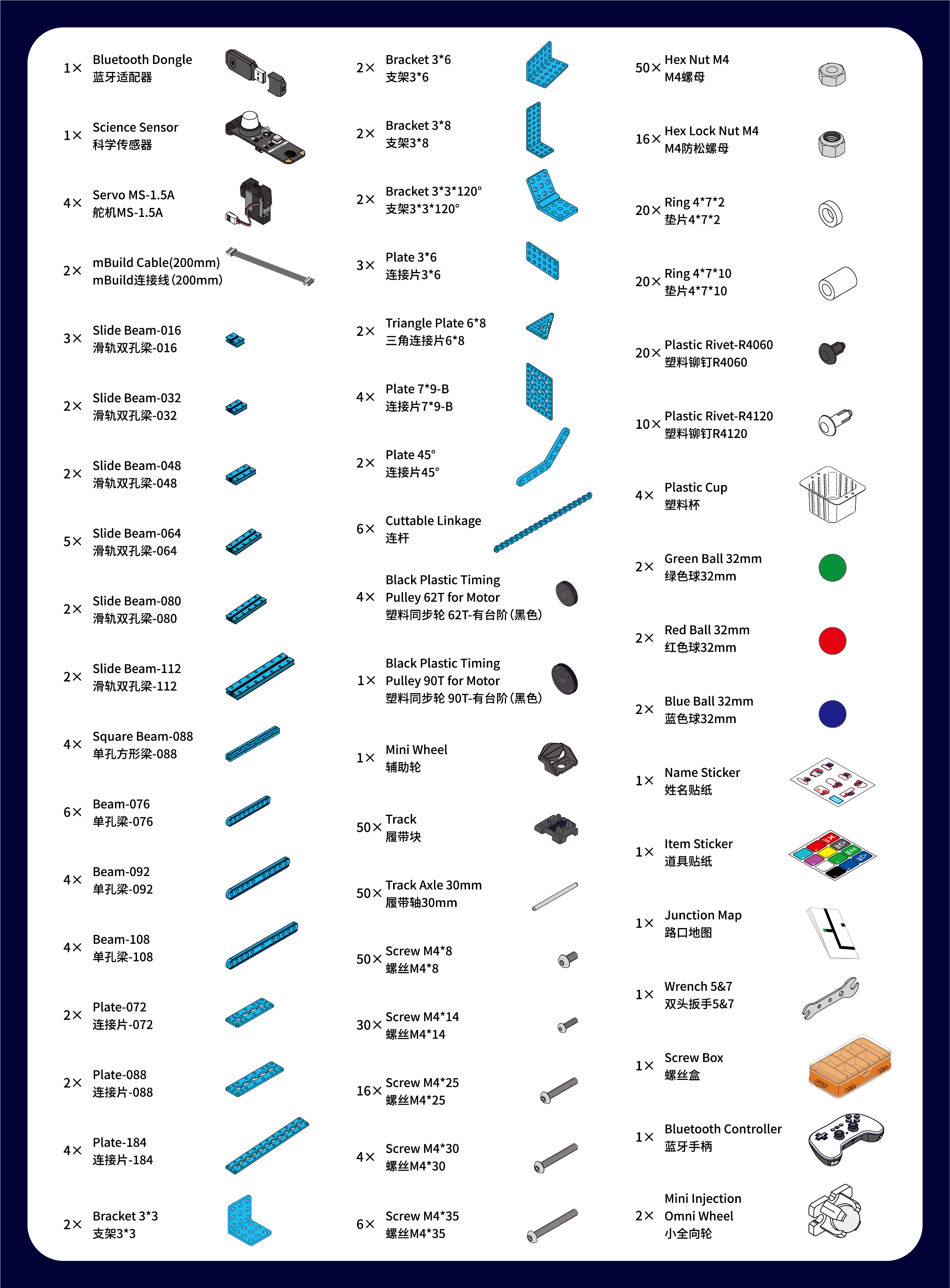 :::warning
Note: Keep the parts properly after each use so that you can reuse them in other projects.
:::warning
Note: Keep the parts properly after each use so that you can reuse them in other projects.
:::
3. Learn about the main components
- This kit contains a variety of electronic and structural parts that you can get to know as you go through the course.
- You can also familiarize yourself with these parts before you start the course to quickly get into the swing of things.
- The kit includes a CyberPi main control board and an mBot2 shield. They work together to power and control other electronic parts, including encoder motors, servos and sensors. | Name | Quantity | Documentation | | --- | --- | --- | | Bluetooth Dongle | 1 | For the operation guide of Bluetooth Dongle, see makeblock.com/en/docs/cyberpi/wireless-adapter | | Science Sensor | 1 | For technical information on Science Sensor, see makeblock.com/en/docs/cyberpi/science_sensor | | Servo MS-1.5A | 4 | For technical information on Servo MS-1.5A, see makeblock.com/en/docs/cyberpi/ms-1.5a_servo | | Bluetooth Controller | 1 | For technical information on Bluetooth Controller, see makeblock.com/en/docs/cyberpi/bluetooth_controller |
4. Courses
Documents are on the way. Stay tuned!
5. Explore beyond
You can use the parts to build your own robot and program it using mBlock5 to bring your ideas to life.
Programming guide
To program the parts in mBlock5, you need to add the corresponding extensions first.
For example, if you uses a CyberPi, an mBot2 shield, encoder motors, and an ultrasonic sensor to build the robot, after adding **CyberPi **to the device library and connecting it, you also need to add the mBot2 shield extension (which contains the blocks for encoder motors) and the ultrasonic sensor extension.
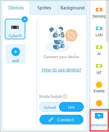
 Alternatively, you can add mBot2 to the device library to load the required extensions in one go.
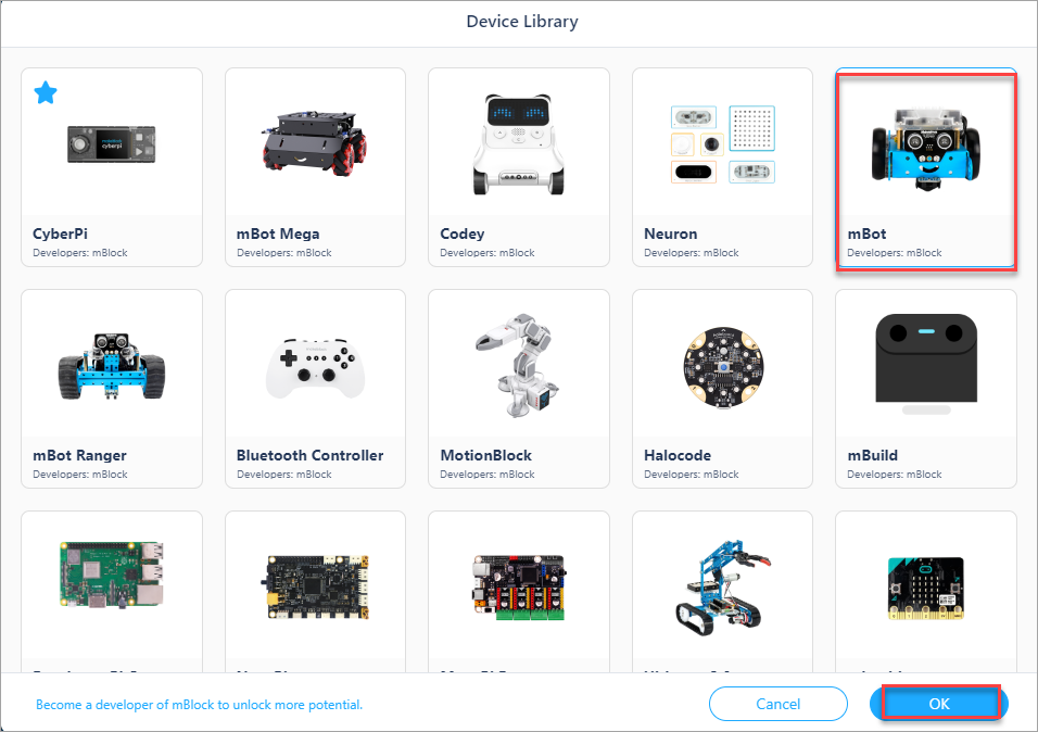 :::tips
Note: This mBot2 one-time loading feature is currently only supported in the web version of mBlock5.
:::
:::tips
Note: This mBot2 one-time loading feature is currently only supported in the web version of mBlock5.
:::
After adding the extensions successfully, you can drag the blocks to the Blocks area and start programming.
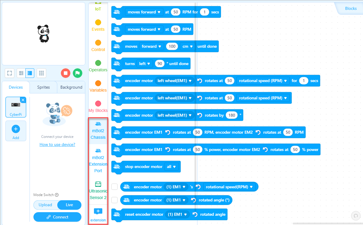
Get more hardware
There is a wide range of peripherals that can be added to the kit to bring your ideas to life. Contact us (https://education.makeblock.com/contact-us/) if you want to take them home.
You can also find more technical information from our CyberPi Series User Manual makeblock.com/en/docs/cyberpi
6. About the competition
MakeX is an international robotics competition and education platform that promotes multidisciplinary learning within the fields of science and technology. It aims at building a world where STEAM education is highly appreciated and where young people are passionate about innovation by engaging them in exciting Robotics Competition, STEAM Carnival, Tech Event, Educational Conference etc.
MakeX Starter is a multi-tasking competition program for elementary school students aged 6-13.
The competition integrates the automatic stage and the manual stage, which greatly enhances fun and participation experience of the competition. The concept of multiple missions and the alliance cooperation design fully exercises the abilities of critical thinking and strategic planning of contestants, as well as improve the ability of communication and cooperation between alliance teams.
 To view information about registration, entry requirements, and available competitions, visit www.makex.cc/en
Or contact us by email: makex_overseas@makeblock.com (overseas) makex@makeblock.com (China)
7. Online support
If you encounter any product quality issues or find any parts missing when you open the package, contact us for after-sales services at support@makeblock.com
We would also appreciate it if you could give us your feedback on the product at cyber.list@makeblock.com
8. More information
CyberPi Series User Manual makeblock.com/en/docs/cyberpi CyberPi Operation Guide makeblock.com/en/docs/cyberpi/cyberpi-start mBot2 Operation Guide makeblock.com/en/docs/cyberpi/mbot2-start Python API Documentation for CyberPi makeblock.com/en/docs/mcode/cyberpi-api mBlock 5 Online Help makeblock.com/en/docs/mblock-5 mBlock-Python Editor Online Help makeblock.com/en/docs/mcode 2022 MakeX Educational Competition Kits makeblock.com/en/docs/cyberpi/22makex
Introduction to the 2022 MakeX Starter Arena
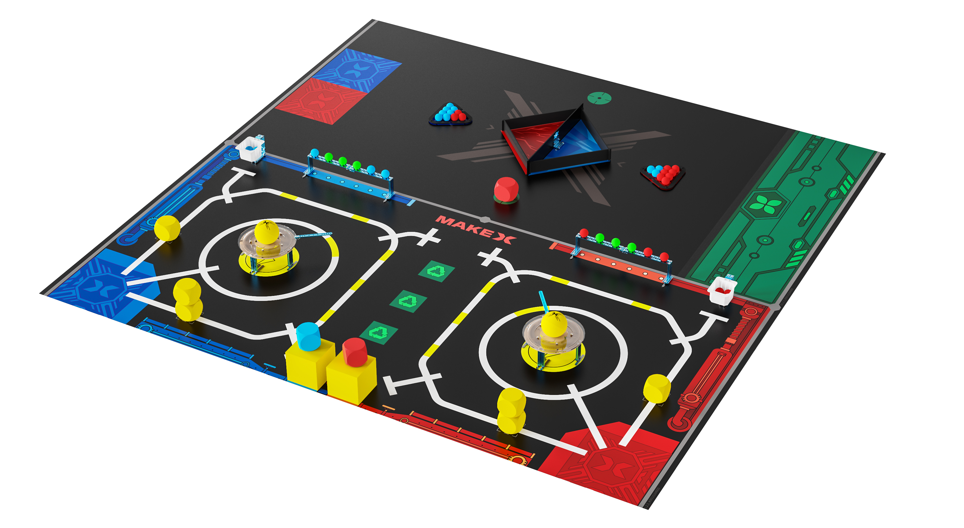
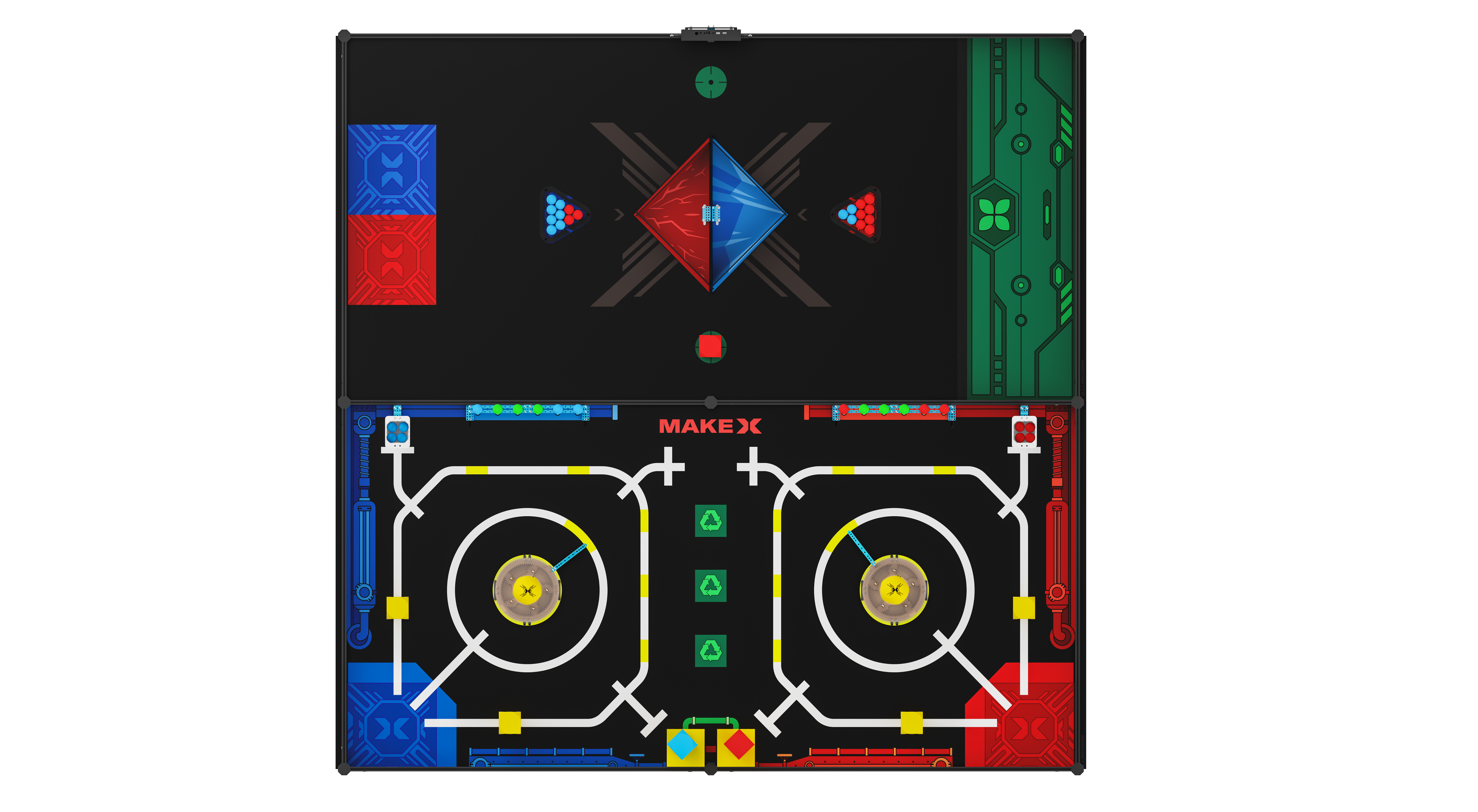
This kit does not include the MakeboX and frame.
1. Basic information
2022 MakeX Starter Arena
| Name | 2022 MakeX Starter Arena |
|---|---|
| SKU | P1090044 |
| EAN | 6928819513624 |
| Package type | Paper box |
| Package size | 522162329 mm |
| 3mm (thickness)*80mm (inner diameter)*1190mm (length) (Map) | |
| Gross weight (including packaging) | 5.68kg (88.2oz) |
| Others | Remote control and battery not included |
2. Overview
If you want to save money by making your own frames, only want to use the arena for practice, or have already purchased a MakeX starter frame for the 2020 or 2021 season, then we recommend you purchase the **2022 MakeX Starter Arena **for practice or arena upgrades.
3. Parts list
| Name | 2022 MakeX Starter Arena |
|---|---|
| Zero Carbon Map | 2 |
| Red Cube 70mm | 3 |
| Blue Cube 70mm | 2 |
| Yellow Cube 70mm | 6 |
| Yellow Cube 120mm | 2 |
| Red Ball 32mm | 2 |
| Blue Ball 32mm | 20 |
| Green Ball 32mm | 60 |
| PU Ball | 1 |
| Wrench 5&7 | 1 |
| Scredriver Cross&2.5mm | 1 |
| Plastic Cup | 1 |
| Bracket 3*8 | 60 |
| Hinge 40*24mm | 4 |
| Plate-184 | 20 |
| Slide Beam-064 | 2 |
| Plate 3*6 | 60 |
| Bracket 3*3 | 2 |
| Plastic Rivet-R4060 | 6 |
| Hex Lock Nut M4 | 1 |
| Round Ball Rack | 2 |
| Beam-140 | 12 |
| Board A | 5 |
| Board B | 5 |
| Stickers | 2 |
| Bracket 3*6 | 2 |
| Triangle board | 5 |
| Screw M4*8 | 1 |
| Screw M4*14 | 1 |
| Hex Nut M4 | 1 |
| Strip iron | 40 |
| Magnetic column | 35 |
| Magnet sheet | 40 |
| Plate-184 | 20 |
4. Assembly instruction
After checking the number of parts, refer to the following document to assemble the 2022 MakeX Starter Arena. 2022 MakeX Starer零碳行动场地搭建步骤图_说明书_V1.0_D1.1.2_KD010419000_view.pdf 2022 MakeX Starer零碳行动场地搭建步骤图_说明书_V1.0_D1.1.2_KD010419000_view.pdf
5. More information
Getting started with the 2022 MakeX Starter Educational Competition Kit:makeblock.com/en/docs/cyberpi/22starter-start Introduction to the 2022 MakeX Starter Add-on Pack:makeblock.com/en/docs/cyberpi/starter-add-on mBlock online help:makeblock.com/en/docs/cyberpi/mbot2-mobile-coding mBot2 operation guide: makeblock.com/en/docs/cyberpi/mbot2-start Introduction to the 2022 MakeX competitions and kits:makeblock.com/en/docs/cyberpi/22makex
Introduction to the 2022 MakeX Starter Arena and Frame
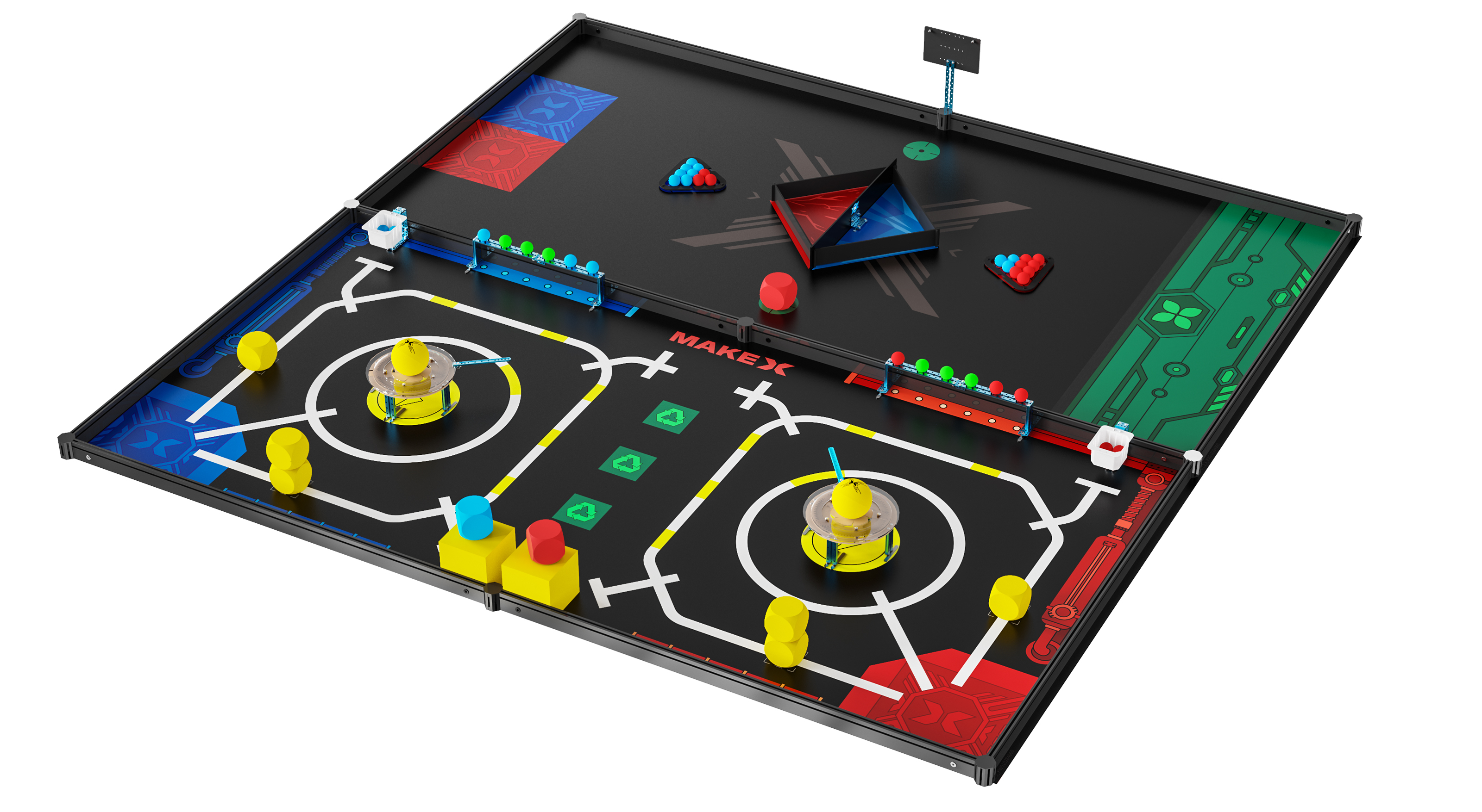

This kit does not include the MakeboX.
1. Basic information
2022 MakeX Starter Arena and Frame
| Name | 2022 MakeX Starter Arena and Frame |
|---|---|
| SKU | P1090045 |
| EAN | 6928819513617 |
| Package type | Paper box |
| Package size | 445357250mm |
| 1220135120mm | |
| Map packaging: 3mm(thickness)*80mm(inner diameter)*1190mm(length) | |
| Gross weight (including packaging) | 15.48kg (546.04oz) |
| Others | Remote control and battery not included |
2. Overview
If this is your first MakeX Starter competition, or if you would like to purchase a complete package for practice or hosting a MakeX competition, purchase the** 2022 MakeX Starter Arena and Frame**. This set includes the MakeX Starter Frame Expansion Kit V2.0 and the 2022 MakeX Starter Arena.
3. Parts list
Make sure the following parts are included in the kit. If there is any missing part, contact our after-sales service or distributors.
| Name | **2022 MakeX Starter and Frame ** |
|---|---|
| Zero Carbon Map | 1 |
| Red Cube 70mm | 1 |
| Blue Cube 70mm | 1 |
| Yellow Cube 70mm | 6 |
| Yellow Cube 120mm | 2 |
| Red Ball 32mm | 17 |
| Blue Ball 32mm | 17 |
| Green Ball 32mm | 6 |
| PU Ball | 2 |
| Wrench 5&7 | 1 |
| Allen Key 1.5mm | 1 |
| Scredriver Cross&2.5mm | 1 |
| Plastic Cup | 2 |
| Bracket 3*8 | 4 |
| Hinge 40*24mm | 2 |
| Plate-184 | 5 |
| Slide Beam-064 | 12 |
| Plate 3*6 | 5 |
| Bracket 3*3 | 2 |
| Plastic Rivet-R4060 | 60 |
| Hex Lock Nut M4 | 20 |
| Round Ball Rack | 2 |
| Beam-140 | 2 |
| Board A | 4 |
| Board B | 4 |
| Stickers | 1 |
| Bracket 3*6 | 2 |
| Triangle board | 1 |
| Screw M4*8 | 60 |
| Screw M4*14 | 20 |
| Hex Nut M4 | 60 |
| Strip iron | 35 |
| Magnetic column | 40 |
| Magnet sheet | 40 |
| Flat Beam 1550-1126 | 12 |
| Octagonal Pillar-45 | 12 |
| Octagonal Pillar Cover | 24 |
| Flat Beam Lock | 24 |
| Handled Hex Allen Key | 1 |
| Plate-184 | 5 |
| Rectangular Nut M4 | 2 |
| MakeboX Bracket | 1 |
4. Assembly instruction
After checking the number of parts, refer to the following document to assemble the 2022 MakeX Starter Arena. 2022 MakeX Starer零碳行动场地搭建步骤图_说明书_V1.0_D1.1.2_KD010419000_view.pdf
5. More information
Getting started with the 2022 MakeX Starter Educational Competition Kit:makeblock.com/en/docs/cyberpi/22starter-start mBlock online help:makeblock.com/en/docs/cyberpi/mbot2-mobile-coding mBot2 operation guide: makeblock.com/en/docs/cyberpi/mbot2-start Introduction to the 2022 MakeX competitions and kits:makeblock.com/en/docs/cyberpi/22makex
Introduction to the MakeX Starter Frame Expansion Kit V2.0
1. Basic information
MakeX Starter Frame Expansion Kit V2.0
| Name | MakeX Starter Frame Expansion Kit V2.0 |
|---|---|
| SKU | P1090046 |
| EAN | 6928819513631 |
| Package type | Paper box |
| Package size | 290223100 mm |
| 1220135120 mm | |
| Gross weight (including packaging) | 10.1kg (356.3oz) |
| Others | Remote control and battery not included |
2. Overview
For the 2022 MakeX Starter competition, we have 2 different sets of arena and a newly upgraded frame expansion kit for users with different needs.
If you have purchased the** 2022 MakeX Starter Arena **and want to have a better contest experience with a frame, or if you are hosting MakeX competitions, which require standard frames, then you can purchase MakeX Starter Frame Expansion Kit V2.0 as an add-on.
Version statement
- To reduce the time spent in arena assembly, and to avoid discrepancy in referee review due to incorrect arena orientation, we standadize the length of the flat beams for the 2022 season.
- The MakeX Starter Frame Expansion Kit V2.0 uses only 1126mm flat beams, replacing the 1173mm flat beams of Kit V1.0. This makes Kit V2.0 shorter in width by 54mm compared to** Kit V1.0**.
Difference in usage scenarios
The differences in the usage scenarios between Kit V1.0 and Kit V2.0 are as follows:
| Practice | Hosting competitions | MakeX competitions | |
|---|---|---|---|
| Kit V1.0 | Supports | Supports | Not support |
| Kit V2.0 | Supports | Supports | Supports |
"Double frame" mode
Ideally, you should build a complete 2022 MakeX Starter arena on a field of approximately 2.44*2.44m as shown in assembly instruction.
But in many cases, you may not have a large enough field. Therefore, we give you 2 extra flat beams in the Kit V2.0, so you can build 2 complete "0" shaped frames. Although this will be different from the final "8" shaped arena, it will help you teach and practice for the MakeX Starter competition in a more flexible field.
3. Parts list
Make sure the following parts are included in the kit. If there is any missing part, contact our after-sales service or distributors.
| Name | MakeX Starter Frame Expansion Kit V2.0 |
|---|---|
| Wrench 5&7 | 1 |
| Scredriver Cross&2.5mm | 1 |
| Plate 3*6 | 1 |
| Screw M4*14 | 10 |
| Hex Nut M4 | 8 |
| Octagonal Pillar-45 | 12 |
| Octagonal Pillar Cover | 24 |
| Flat Beam Lock | 24 |
| Handled Hex Allen Key | 1 |
| Plate-184 | 1 |
| Rectangular Nut M4 | 5 |
| Flat Beam 550-1126 | 12 |
| MakeboX Bracket | 1 |
4. Assembly instruction
After checking the number of parts, refer to the following document to assemble the 2022 MakeX Starter Arena. 2022 MakeX Starer零碳行动场地搭建步骤图_说明书_V1.0_D1.1.2_KD010419000_view.pdf
5. More information
Getting started with the 2022 MakeX Starter Educational Competition Kit:makeblock.com/en/docs/cyberpi/22starter-start mBlock online help:makeblock.com/en/docs/cyberpi/mbot2-mobile-coding mBot2 operation guide: makeblock.com/en/docs/cyberpi/mbot2-start mBot2 operation guide: makeblock.com/en/docs/cyberpi/mbot2-start Introduction to the 2022 MakeX competitions and kits:makeblock.com/en/docs/cyberpi/22makex
Getting Started with the 2022 MakeX Explorer Educational Competition Kit
Thank you for choosing the 2022 MakeX Explorer Educational Competition Kit. If you are using this kit for the first time, we recommend that you read these instructions carefully to get the most out of it.
1. Unpacking and check
Make sure the following parts are included in the kit. If there is any missing part, contact our after-sales service or distributors.
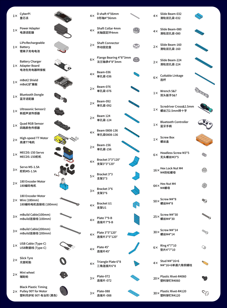 :::warning
Note: Keep the parts properly after each use so that you can reuse them in other projects.
:::warning
Note: Keep the parts properly after each use so that you can reuse them in other projects.
:::
2. Learn about the main components
- This kit contains a variety of electronic and structural parts that you can get to know as you go through the course.
- You can also familiarize yourself with these parts before you start the course to quickly get into the swing of things.
- The kit includes a CyberPi main control board and an mBot2 shield. They work together to power and control other electronic parts, including encoder motors, servos and sensors. | Name | Quantity | Documentation | | --- | --- | --- | | CyberPi | 1 | For technical information on CyberPi, see makeblock.com/en/docs/cyberpi/cyberpi For the operation guide of CyberPi, see makeblock.com/en/docs/cyberpi/cyberpi-start | | mBot2 Shield | 1 | For technical information on mBot2 Shield, see makeblock.com/en/docs/cyberpi/mbot2-shield | | Bluetooth Controller | 1 | For technical information on Bluetooth Controller, see makeblock.com/en/docs/cyberpi/bluetooth_controller | | Bluetooth Dongle | 1 | For the operation guide of Bluetooth Dongle, see makeblock.com/en/docs/cyberpi/wireless-adapter | | Ultrasonic Sensor | 1 | For technical information on Ultrasonic Sensor, see makeblock.com/en/docs/cyberpi/ultrasonic_sensor_2 | | Quad RGB Color Sensor | 1 | For technical information on Quad RGB Color Sensor, see makeblock.com/en/docs/cyberpi/quad_rgb_sensor | | MS-1.5A Servo | 3 | For technical information on MS-1.5A Servo, see http://docs.makeblock.com/diy-platform/en/electronic-modules/motors/meds15-servo-motor.html | | 130 High-speed DC Motor | 2 | For technical information on 130 High-speed DC Motor, see makeblock.com/en/docs/cyberpi/dh68v8 | | MECDS-150 Servo | 1 | For technical information on MECDS-150 Servo, see http://docs.makeblock.com/diy-platform/en/electronic-modules/motors/meds15-servo-motor.html | | LiPo Rechargeable Battery | 1 | For technical information on mBot2 Li-ion Rechargeable Battery Enhancement Pack, see makeblock.com/en/docs/cyberpi/mbot2-battery-enhancement | | Battery Charger Adapter Board | 1 | | | Power Adapter | 1 | | | Encoder Motor | 2 | For technical information on Encoding Motor Cable(180mm), see makeblock.com/en/docs/cyberpi/180-optical-encoder-motor | | Encoding Motor Cable(180mm) | 2 | |
3. Courses
Documents are on the way. Stay tuned!
4. Explore beyond
You can use the parts to build your own robot and program it using mBlock5 to bring your ideas to life.
Programming guide
To program the parts in mBlock5, you need to add the corresponding extensions first.
For example, if you use a CyberPi, a mBot2 shield, encoder motors, and an ultrasonic sensor to build the robot, after adding **CyberPi **to the device library and connecting it, you also need to add the mBot2 shield extension (which contains the blocks for encoder motors) and the ultrasonic sensor extension.

 Alternatively, you can add mBot2 to the device library to load the required extensions at once.
 :::tips
Note: This mBot2 one-time loading feature is currently only supported in the web version of mBlock5.
:::
:::tips
Note: This mBot2 one-time loading feature is currently only supported in the web version of mBlock5.
:::
After adding the extensions successfully, you can drag the blocks to the Blocks area and start programming.

Get more hardware
There is a variety of peripherals that can be added to the kit to bring your ideas to life. Contact us (https://education.makeblock.com/contact-us) if you want to take them home.
You can also find more technical information from our CyberPi series User Manual makeblock.com/en/docs/cyberpi
5. About the competition
MakeX is an international robotics competition and education platform that promotes multidisciplinary learning within the fields of science and technology. It aims at building a world where STEAM education is highly appreciated and where young people are passionate about innovation by engaging them in exciting Robotics Competition, STEAM Carnival, Tech Event, Educational Conference, etc.
MakeX Explorer is a confrontational competition program for elementary and junior high school students aged 8-15.
This program fully integrates the essence of sports events and is highly interesting and a delight to watch. The competition requires the contestants to design and build robots from scratch, which systematically develops the contestants' comprehensive abilities in robot design, mechanical construction, and programming. Also, the form of alliance confrontation improves the contestants' ability to solve imperative problems and strategic thinking.
 To view information about registration, entry requirements, and available competitions, visit www.makex.cc
Or contact us by email: makex_overseas@makeblock.com (overseas) makex@makeblock.com (China)
6. Online support
If you encounter any product quality issues or find any parts missing when you open the package, contact us for after-sales services at support@makeblock.com
We would also appreciate it if you could give us your feedback on the product at cyber.list@makeblock.com
7. More information
Introduction to the 2022 MakeX Explorer Educational Competition Kit:makeblock.com/en/docs/cyberpi/22explorer CyberPi Series User Manual makeblock.com/en/docs/cyberpi CyberPi Operation Guide makeblock.com/en/docs/cyberpi/cyberpi-start mBot2 Operation Guide makeblock.com/en/docs/cyberpi/mbot2-start Python API Documentation for CyberPi makeblock.com/en/docs/mcode/cyberpi-api mBlock 5 Online Help makeblock.com/en/docs/mblock-5 mBlock-Python Editor Online Help makeblock.com/en/docs/mcode 2022 MakeX Educational Competition Kits makeblock.com/en/docs/cyberpi/22makex
Introduction to the 2022 MakeX Explorer Arena
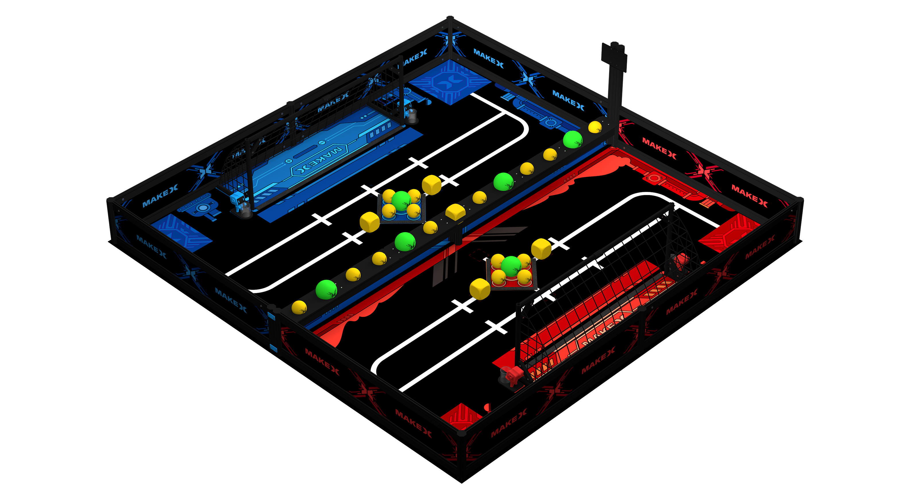
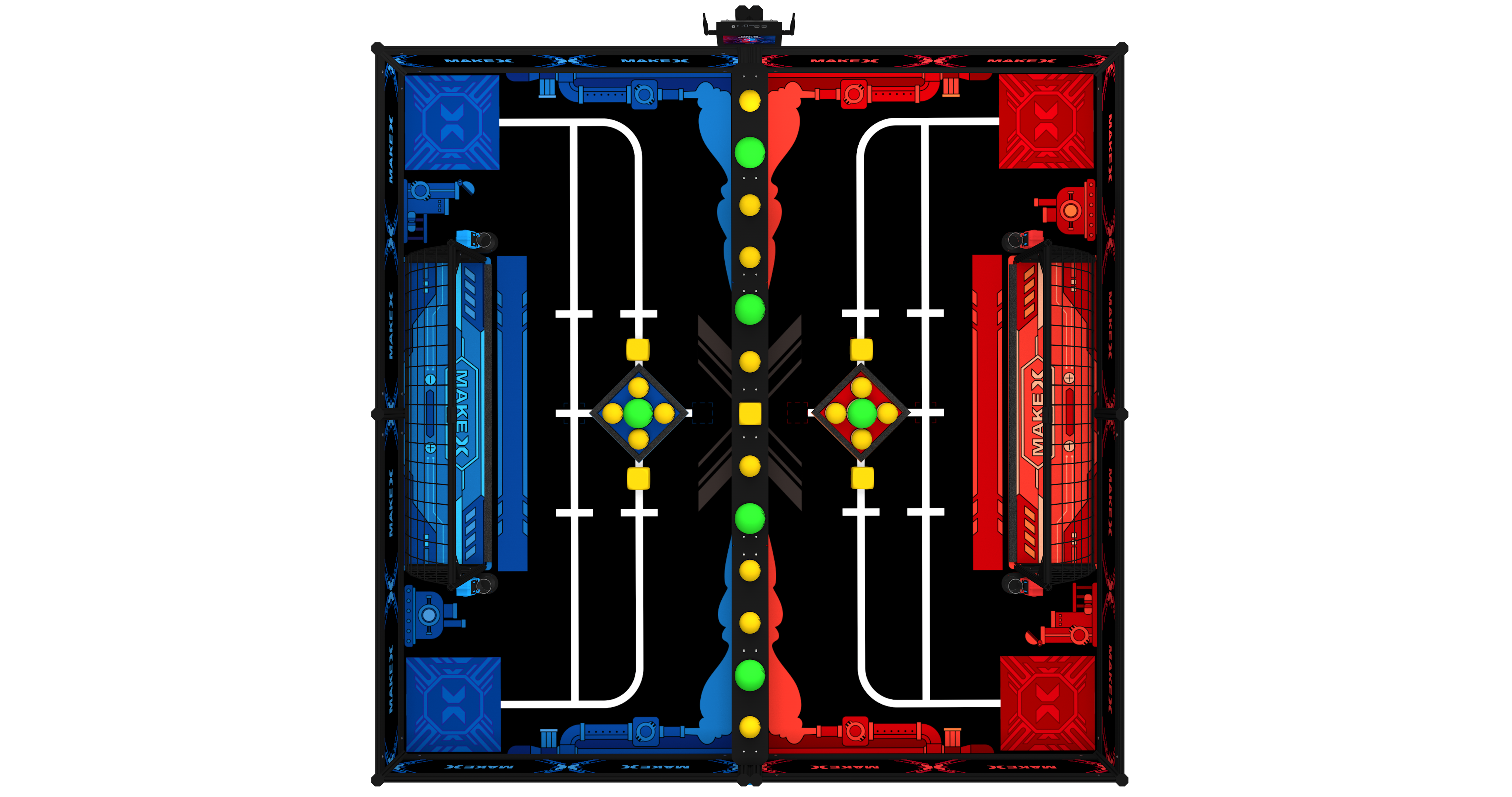
The kit does not include the MakeboX.
1. Basic information
2022 MakeX Explorer Arena
| Name | 2022 MakeX Explorer Arena |
|---|---|
| SKU | P1090040 |
| EAN | 6928819513662 |
| Package type | Paper box |
| Package size | 365355310mm |
| 1175210115mm | |
| 2386.9 * 2426.9 mm(map) | |
| 1175210115mm | |
| Gross weight (including packaging) | 30.775kg (1085.556oz) |
| Others | Remote control and battery not included |
2. Overview
This kit contains a map, a frame, props and other parts needed for the 2022 MakeX Explorer competition, which can be used for offline training and competition hosting.
3. Parts list
Make sure the following parts are included in the kit. If there is any missing part, contact our after-sales service or distributors.
| Name | Quantity |
|---|---|
| Flat Beam 1126 | 16 |
| MakeX Board Blue&Black | 4 |
| MakeX Board Red&Black | 4 |
| Flat Beam 1126 | 4 |
| Octagonal Pillar-600 | 2 |
| Octagonal Pillar-250 | 8 |
| Octagonal Pillar-125 | 2 |
| Middle Board A | 1 |
| Middle Board B | 2 |
| Flat Beam Lock | 40 |
| Extension Connector | 4 |
| 90° Connector | 16 |
| Octagonal Pillar Cover | 24 |
| Rectangular Nut M4 | 30 |
| Plate | 3 |
| Yellow Ball 70mm | 16 |
| Green Ball 100mm | 6 |
| Yellow Cube 70mm | 5 |
| Lean Beam-248 | 4 |
| Lean Beam-424 | 4 |
| Lean Beam-504 | 4 |
| MakeboX Bracket | 1 |
| Height Setting Bar | 8 |
| Flag Bucket | 2 |
| 1 | |
| Max in Red | 1 |
| Screw M3*8 | 2 |
| Flag Bucket | 2 |
| 1 | |
| Max in Blue | 2 |
| Screw M3*8 | 2 |
| Screw M4*40 | 20 |
| Screw M4*14 | 4 |
| Screw M4*8 | 6 |
| Hex Nut M4 | 20 |
| Screw M6*12 | 16 |
| Screw M6*16 | 2 |
| Hex Nut M6 | 18 |
| Spacer 4.2730 | 20 |
| Hook-and-Loop Fastener 20mm (Hook) | 1 |
| Hook-and-Loop Fastener 21mm (Loop) | 2 |
| Goal Net | 2 |
| EVA Tape 20*8mm | 2 |
| Cable Tie | 100 |
| Transparent Tape | 1 |
| 3M Double-sided Nano Tape | 1 |
| Hex Allen Key T30 | 1 |
| Allen Key 5mm | 1 |
| Screwdriver Cross&2.5mm | 1 |
4. Assembly instruction
After checking the number of parts, refer to the following document to assemble the 2022 MakeX Starter Arena. 2022 MakeX Explorer 碳锁先锋_场地搭建步骤_说明书_V1.0_D1.1.2_ KD010421000_preview.pdf
5. More information
Getting started with the 2022 MakeX Explorer Educational Competition Kit:makeblock.com/en/docs/cyberpi/22explorer-start mBlock online help:makeblock.com/en/docs/cyberpi/mbot2-mobile-coding mBot2 operation guide: makeblock.com/en/docs/cyberpi/mbot2-start Introduction to the 2022 MakeX competitions and kits:makeblock.com/en/docs/cyberpi/22makex
Démarrage avec le Kit de Compétition Éducative MakeX Challenge 2022
1. Avant-propos
Merci d'avoir choisi le Kit de Compétition Éducative MakeX Challenge 2022.
Si vous utilisez ce kit pour la première fois, nous vous recommandons de lire attentivement ces instructions pour en tirer le meilleur parti.
2. Déballage et vérification
Assurez-vous que les pièces suivantes sont incluses dans le kit. S'il manque une pièce, contactez notre service après-vente ou nos distributeurs.
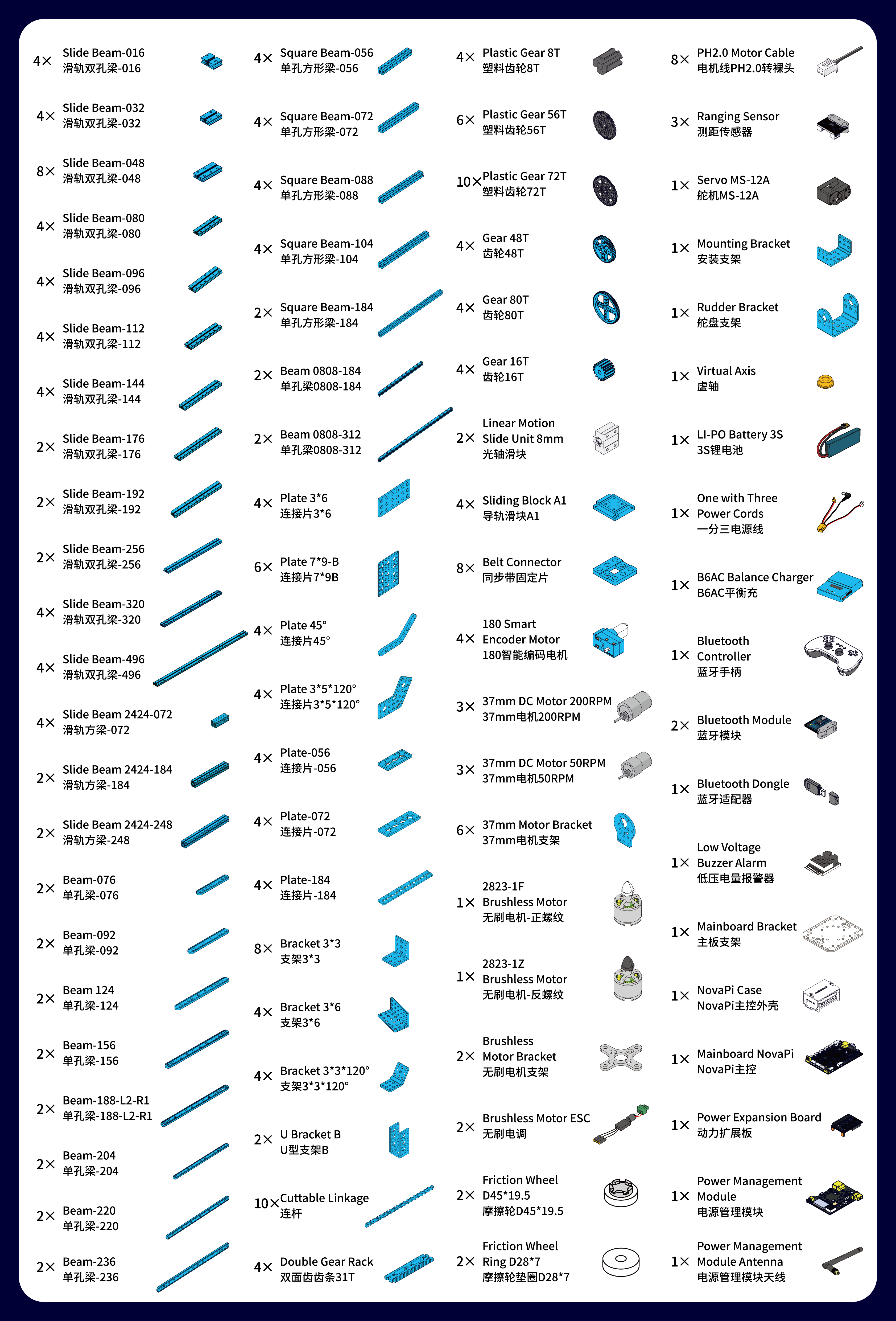
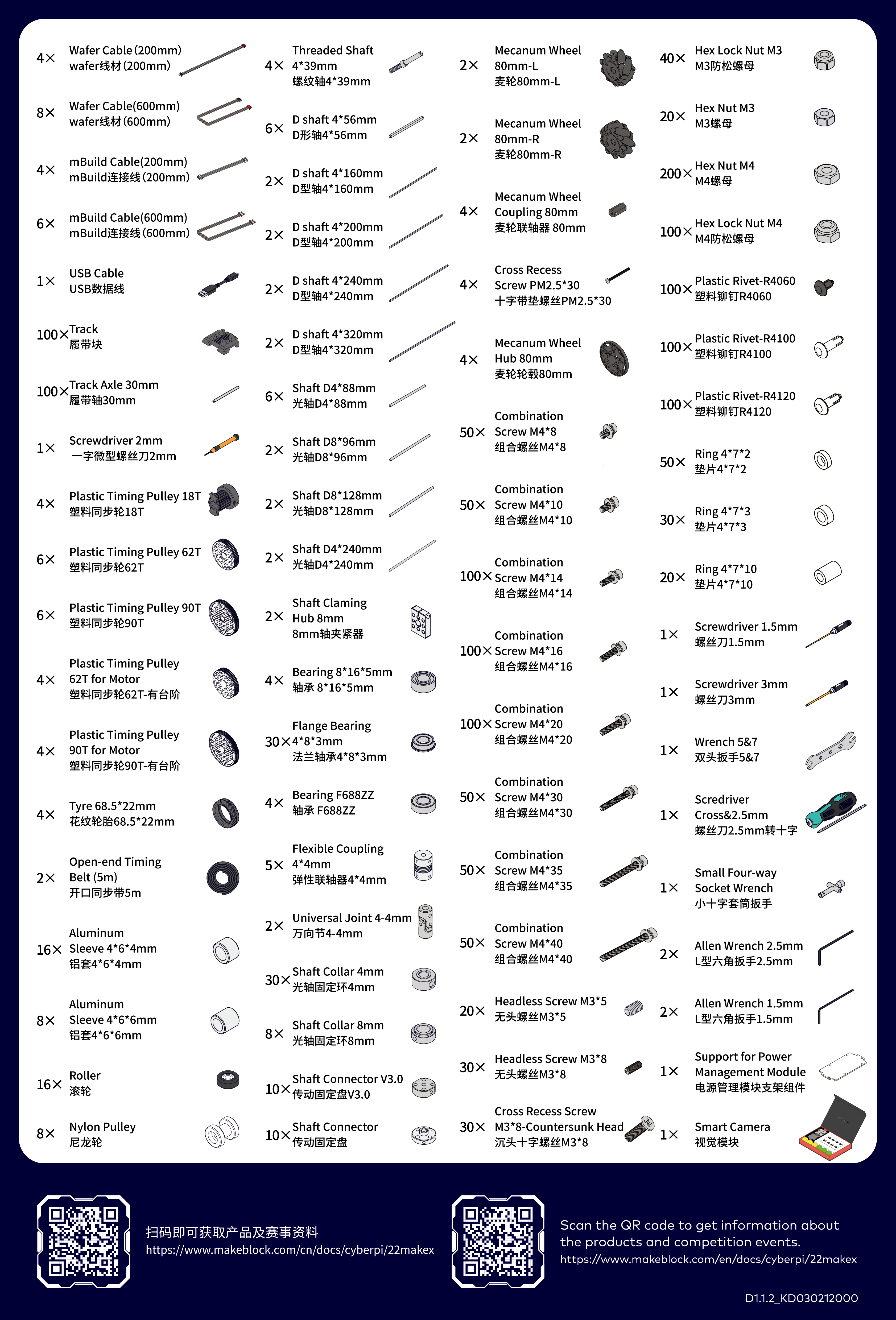
:::warning Note : Conservez correctement les pièces après chaque utilisation afin de pouvoir les réutiliser dans d'autres projets. :::
3. Découvrir les principaux composants
- Ce kit contient une variété de pièces électroniques et structurelles que vous pouvez découvrir au fur et à mesure du cours.
- Vous pouvez également vous familiariser avec ces pièces avant de commencer le cours pour vous mettre rapidement dans le bain.
| Nom | Image | Documentation |
|---|
|
Mainboard NovaPi | 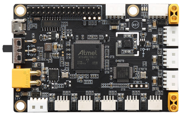 | Pour des informations techniques et le guide d'utilisation sur NovaPi, voir makeblock.com/en/docs/maker_platform/novapi |
|
| Pour des informations techniques et le guide d'utilisation sur NovaPi, voir makeblock.com/en/docs/maker_platform/novapi |
|
Power Expansion Board | 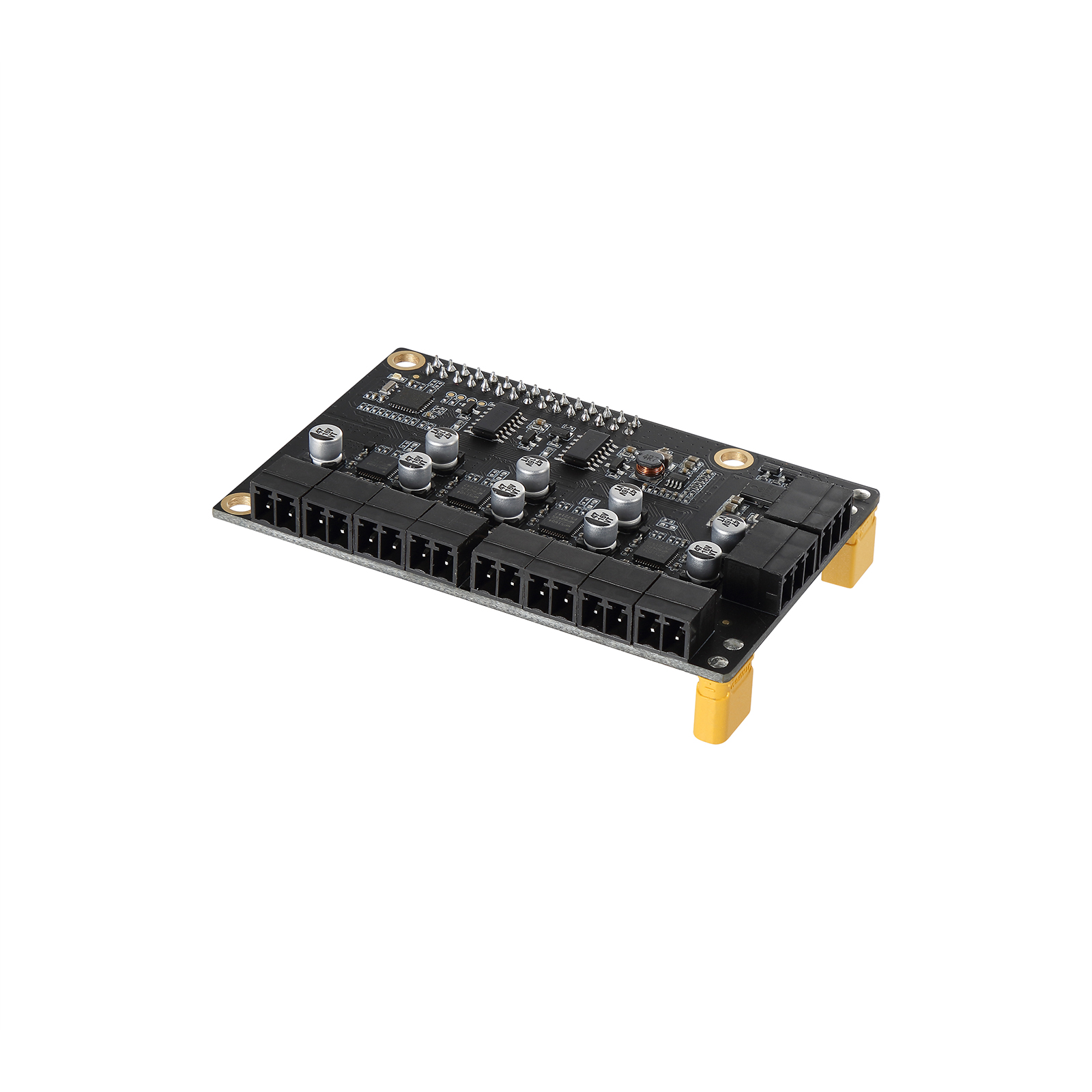 | Pour des informations techniques sur la carte d'extension d'alimentation, voir
makeblock.com/en/docs/maker_platform/power_extension_board |
|
| Pour des informations techniques sur la carte d'extension d'alimentation, voir
makeblock.com/en/docs/maker_platform/power_extension_board |
|
Power Management Module | 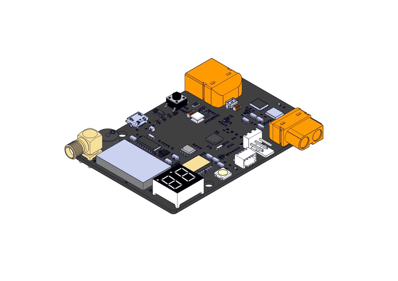 | Pour des informations techniques sur le module de gestion d'alimentation, voir
makeblock.com/en/docs/maker_platform/ayttzq |
|
| Pour des informations techniques sur le module de gestion d'alimentation, voir
makeblock.com/en/docs/maker_platform/ayttzq |
|
180 Smart Encoder Motor |  | Pour des informations techniques sur le moteur 180 Smart Encoder, voir makeblock.com/en/docs/maker_platform/180-smart-encoder-motor |
|
| Pour des informations techniques sur le moteur 180 Smart Encoder, voir makeblock.com/en/docs/maker_platform/180-smart-encoder-motor |
|
Moteur DC 37mm | 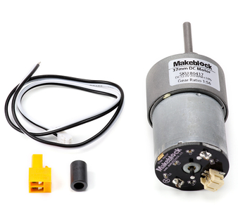 | Pour des informations techniques sur le moteur DC 37mm, voir makeblock.com/en/docs/maker_platform/37-dc-motor |
|
| Pour des informations techniques sur le moteur DC 37mm, voir makeblock.com/en/docs/maker_platform/37-dc-motor |
|
Servo MS-12A | 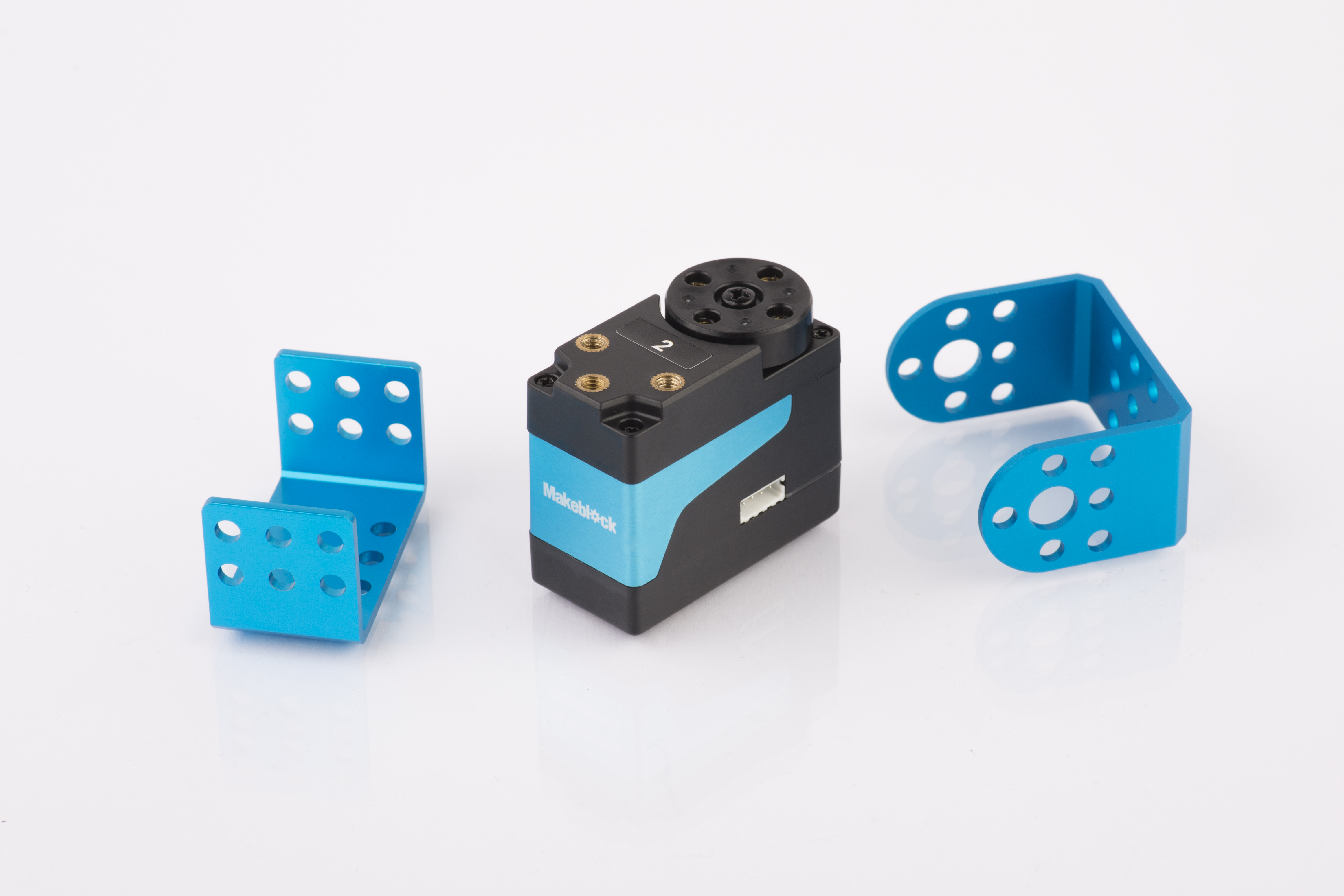 | Pour des informations techniques sur le Servo MS-12A, voir
makeblock.com/en/docs/maker_platform/smart-servo-12a |
|
| Pour des informations techniques sur le Servo MS-12A, voir
makeblock.com/en/docs/maker_platform/smart-servo-12a |
|
Moteur Brushless | 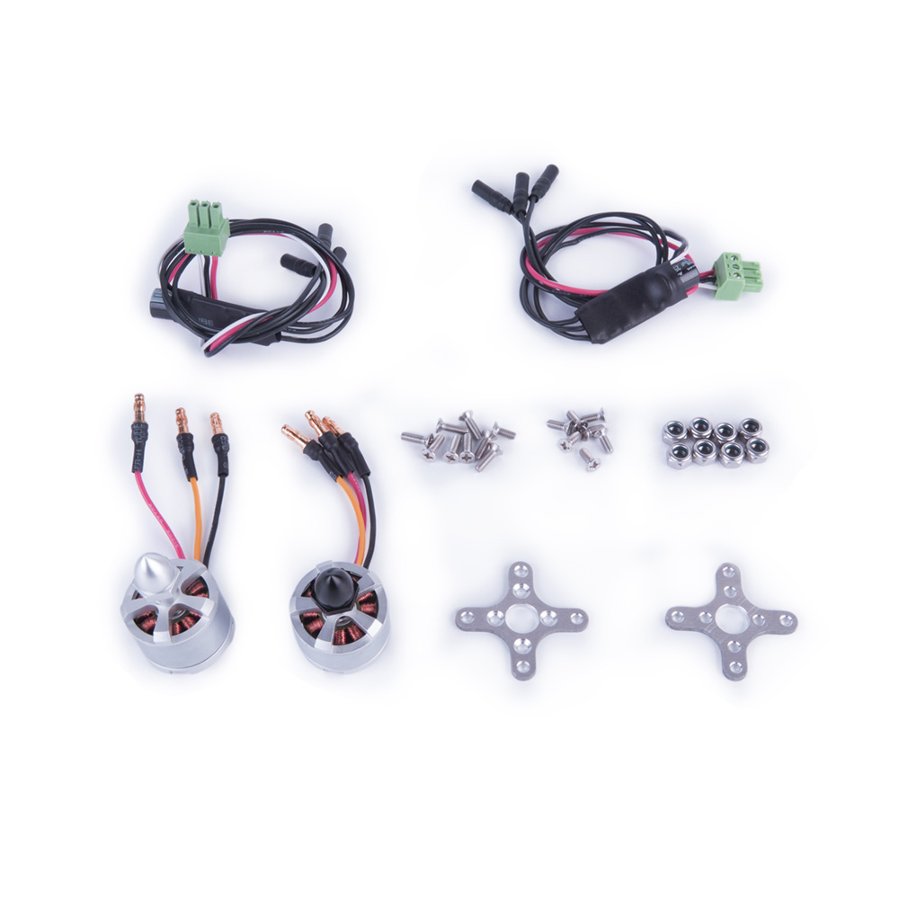 | Pour des informations techniques sur le Moteur Brushless, voir
makeblock.com/en/docs/maker_platform/brushless-motor |
|
| Pour des informations techniques sur le Moteur Brushless, voir
makeblock.com/en/docs/maker_platform/brushless-motor |
|
Pièces structurelles |  | Pour des informations techniques sur les pièces structurelles, voir makeblock.com/en/docs/maker_platform/mechanical_structure |
|
| Pour des informations techniques sur les pièces structurelles, voir makeblock.com/en/docs/maker_platform/mechanical_structure |
|
Dongle Bluetooth |  | Pour le guide d'utilisation du Dongle Bluetooth, voir makeblock.com/en/docs/cyberpi/wireless-adapter |
|
| Pour le guide d'utilisation du Dongle Bluetooth, voir makeblock.com/en/docs/cyberpi/wireless-adapter |
|
Contrôleur Bluetooth | 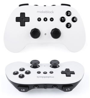 | Pour des informations techniques sur le Contrôleur Bluetooth, voir
makeblock.com/en/docs/cyberpi/bluetooth_controller |
| Pour des informations techniques sur le Contrôleur Bluetooth, voir
makeblock.com/en/docs/cyberpi/bluetooth_controller |
Assemblage simple du châssis
4. Cours
Les documents arrivent. Restez à l'écoute !
5. Explorer au-delà
Vous pouvez utiliser les pièces pour construire votre propre robot et le programmer avec mBlock5 pour donner vie à vos idées.
Guide de programmation
Pour programmer les pièces dans mBlock5, vous devez d'abord ajouter les extensions correspondantes.
Par exemple, si vous utilisez un CyberPi, un bouclier mBot2, des moteurs encodeurs et un capteur ultrasonique pour construire le robot, après avoir ajouté **CyberPi ** à la bibliothèque de périphériques et l'avoir connecté, vous devez également ajouter l'extension bouclier mBot2 (qui contient les blocs pour les moteurs encodeurs) et l'extension capteur ultrasonique.

 Alternativement, vous pouvez ajouter mBot2 à la bibliothèque de périphériques pour charger les extensions requises en une seule fois.
 :::tips
Remarque : Cette fonction de chargement unique mBot2 est actuellement prise en charge uniquement dans la version web de mBlock5.
:::
:::tips
Remarque : Cette fonction de chargement unique mBot2 est actuellement prise en charge uniquement dans la version web de mBlock5.
:::
Après avoir ajouté les extensions avec succès, vous pouvez faire glisser les blocs dans la zone des blocs et commencer la programmation.

Obtenir plus de matériel
Il existe une large gamme de périphériques qui peuvent être ajoutés au kit pour donner vie à vos idées. Contactez-nous (https://education.makeblock.com/contact-us/) si vous souhaitez les obtenir.
Vous pouvez également trouver plus d'informations techniques dans notre Manuel de l'utilisateur de la Série CyberPi makeblock.com/en/docs/cyberpi
6. À propos de la compétition
MakeX est une compétition internationale de robotique et une plateforme éducative qui promeut l'apprentissage multidisciplinaire dans les domaines des sciences et de la technologie. Elle vise à construire un monde où l'éducation STEAM est très appréciée et où les jeunes sont passionnés par l'innovation en les engageant dans des compétitions de robotique passionnantes, des carnavals STEAM, des événements technologiques, des conférences éducatives, etc.
Le MakeX Challenge est un programme de compétition très confrontatif pour les élèves du secondaire et de l'enseignement professionnel âgés de 11 à 18 ans.
Ce programme est très confrontatif et agréable à regarder, et les règles simples et faciles à comprendre améliorent l'expérience globale de participation et d'engagement. La conception et la construction de robots plus grands et la programmation peuvent mieux améliorer les capacités de conception des concurrents et les capacités de pensée multidimensionnelle des robots avancés. De plus, les concurrents exercent la pensée logique, l'analyse stratégique, la communication et la coopération, et améliorent les capacités de prise de décision dans la compétition.
 Pour consulter des informations sur l'inscription, les conditions d'admission et les compétitions disponibles, visitez www.makex.cc/en
Ou contactez-nous par email : makex_overseas@makeblock.com (à l'étranger) makex@makeblock.com (Chine)
7. Support en ligne
Si vous rencontrez des problèmes de qualité du produit ou si vous constatez des pièces manquantes lorsque vous ouvrez l'emballage, contactez-nous pour des services après-vente à support@makeblock.com
Nous vous serions également reconnaissants si vous pouviez nous donner votre avis sur le produit à cyber.list@makeblock.com
8. Plus d'informations
Manuel de l'utilisateur de la Série CyberPi makeblock.com/en/docs/cyberpi
Guide d'utilisation de CyberPi makeblock.com/en/docs/cyberpi/cyberpi-start
Introduction au Kit de Compétition Éducative MakeX Challenge 2022 makeblock.com/en/docs/cyberpi/22challenge
Guide d'utilisation de mBot2 makeblock.com/en/docs/cyberpi/mbot2-start
Documentation API Python pour CyberPi makeblock.com/en/docs/mcode/cyberpi-api
Aide en ligne de mBlock 5 makeblock.com/en/docs/mblock-5
Aide en ligne de l'éditeur mBlock-Python makeblock.com/en/docs/mcode
Kits de Compétition Éducative MakeX 2022 makeblock.com/en/docs/cyberpi/22makex
Getting Started with the 2022 MakeX Challenge Upgrade Pack for Intelligent Innovator
1. Foreword
Thank you for choosing the 2022 MakeX Challenge the 2022 MakeX Challenge Upgrade Pack for Intelligent Innovator.
If you are using this kit for the first time, we recommend that you read these instructions carefully to get the most out of it.
2. Unpacking and check
Make sure the following parts are included in the kit. If there is any missing part, contact our after-sales service or distributors.
 :::warning
Note: Keep the parts properly after each use so that you can reuse them in other projects.
:::warning
Note: Keep the parts properly after each use so that you can reuse them in other projects.
:::
3. Learn about the main components
- This kit contains a variety of electronic and structural parts that you can get to know as you go through the course.
- You can also familiarize yourself with these parts before you start the course to quickly get into the swing of things.
| Name | Picture | Documentation |
| --- | --- | --- |
| 180 Smart Encoder Motor |
 | For technical information on 180 Smart Encoder Motor, see
makeblock.com/en/docs/maker_platform/180-smart-encoder-motor |
| Servo MS-12A |
| For technical information on 180 Smart Encoder Motor, see
makeblock.com/en/docs/maker_platform/180-smart-encoder-motor |
| Servo MS-12A |  | For technical information on Servo MS-12A, see
makeblock.com/en/docs/maker_platform/smart-servo-12a |
| Mechanical / structural parts |
| For technical information on Servo MS-12A, see
makeblock.com/en/docs/maker_platform/smart-servo-12a |
| Mechanical / structural parts |  | For technical information on Mechanical / structural parts, see makeblock.com/en/docs/maker_platform/mechanical_structure |
4. Courses
Documents are on the way. Stay tuned!
5. Explore beyond
You can use the parts to build your own robot and program it using mBlock5 to bring your ideas to life.
Get more hardware
There is a wide range of peripherals that can be added to the kit to bring your ideas to life. Contact us (https://education.makeblock.com/contact-us/) if you want to take them home.
You can also find more technical information from our CyberPi Series User Manual makeblock.com/en/docs/cyberpi
6. About the competition
MakeX is an international robotics competition and education platform that promotes multidisciplinary learning within the fields of science and technology. It aims at building a world where STEAM education is highly appreciated and where young people are passionate about innovation by engaging them in exciting Robotics Competition, STEAM Carnival, Tech Event, Educational Conference, etc.
MakeX Challenge is a highly confrontational competition program for middle and vocational school students aged 11-18.
This program is very confrontational and enjoyable to watch, and the simple and easy-to-understand rules enhance the overall experience of participation and engagement. The design and construction of bigger robots and programming can better improve the contestants' design abilities and multi-dimensional thinking abilities of advanced robots. Also, the contestants are exercising logical thinking, strategic analysis, communication and cooperation, and improving decision-making abilities in the competition.
 To view information about registration, entry requirements, and available competitions, visit www.makex.cc/en
Or contact us by email: makex_overseas@makeblock.com (overseas) makex@makeblock.com (China)
7. Online support
If you encounter any product quality issues or find any parts missing when you open the package, contact us for after-sales services at support@makeblock.com
We would also appreciate it if you could give us your feedback on the product at cyber.list@makeblock.com
8. More information
CyberPi Series User Manual makeblock.com/en/docs/cyberpi CyberPi Operation Guide makeblock.com/en/docs/cyberpi/cyberpi-start Introduction to the 2022 MakeX Challenge Upgrade Pack for Intelligent Innovator makeblock.com/en/docs/cyberpi/challenge-upgrade mBot2 Operation Guide makeblock.com/en/docs/cyberpi/mbot2-start Python API Documentation for CyberPi makeblock.com/en/docs/mcode/cyberpi-api mBlock 5 Online Help makeblock.com/en/docs/mblock-5 mBlock-Python Editor Online Help makeblock.com/en/docs/mcode Introduction to the 2022 MakeX Educational Competition Kits makeblock.com/en/docs/cyberpi/22makex
Introduction to the 2022 MakeX Challenge Arena
Includes only some of the parts and needs to be used with the 2020-2021 MakeX Challenge Arena for Intelligent Innovator.
1. Basic information
2022 MakeX Challenge Arena
| Name | 2022 MakeX Challenge Arena |
|---|---|
| SKU | P1090036 |
| EAN | 6928819513570 |
| Package type | Paper box |
| Package size | 663388255 mm |
| 290223100 mm | |
| 1000284112 mm*2 | |
| 1056384293 mm | |
| 522162329 mm | |
| 2.0980525 mm(Metal net) | |
| 390390185(Hanging Basket) | |
| 3mm(thickness)*92mm(inner diameter)*1590mm(length)(Map) | |
| Gross weight (including packaging) | 83.05KG (2929.5oz) |
| Others | Remote control and battery not included |
2. Overview
This kit contains the maps, frames, props, and other parts needed for the 2022 MakeX Challenge competition, which can be used for offline training and competition hosting.
3. Parts list
| Name | Quantity |
|---|---|
| Metal Net | 6 |
| Hanging Basket | 2 |
| Bottle Red&Black | 12 |
| Bottle Blue&Black | 12 |
| Flat Beam Lock | 126 |
| Flat Beam Lock 45°-Left | 12 |
| Flat Beam Lock 45°-Right | 12 |
| Octagonal Pillar-960 | 12 |
| Flat Beam 960 | 6 |
| Flat Beam 960 | 36 |
| Bottle Support | 12 |
| Cube Partition Board | 3 |
| Cube Cover Board | 3 |
| Black Protection Board | 2 |
| Makex Board Blue&Black | 7 |
| Makex Board Red&Black | 7 |
| Yellow Cube 120mm | 9 |
| Cube Sticker A | 5 |
| Cube Sticker B | 5 |
| Yellow Ball 70mm | 64 |
| Octagonal Pillar-400 | 4 |
| Octagonal Pillar-250 | 4 |
| Flat Beam 220 | 10 |
| Flat Beam 160 | 22 |
| Flat Beam 45° | 12 |
| Octagonal Pillar Cover | 28 |
| Flat Beam Cover | 22 |
| Allen Key | 3 |
| Rectangular Nut M4 | 32 |
| Screw M4*10 | 12 |
| Double-sided Fabric Tape | 1 |
| 3M Double-sided Nano Tape | 1 |
| Octagonal Pillar-45 | 4 |
| Hook-and-Loop Fastener 1150*25mm (Loop) | 4 |
| Combination Screw M4*8 | 20 |
| Screwdriver Cross&2.5mm | 1 |
| Energy Innovator Map | 1 |
4. Assembly instruction
After checking the number of parts, refer to the following document to assemble the 2022 MakeX Challenge Arena. 2022 MakeX Challenge 碳锁先锋_场地搭建步骤_说明书_V1.0_D1.1.1_KD010420000_preview.pdf
5. More information
Getting started with the 2022 MakeX Challenge Educational Competition Kit:makeblock.com/en/docs/cyberpi/22challenge-start mBlock online help:makeblock.com/en/docs/cyberpi/mbot2-mobile-coding mBot2 operation guide: makeblock.com/en/docs/cyberpi/mbot2-start Introduction to the 2022 MakeX competitions and kits:makeblock.com/en/docs/cyberpi/22makex
Introduction to the 2022 MakeX Challenge Upgrade Arena for Intelligent Innovator
1. Basic information
| Name | 2022 MakeX Challenge Upgrade Arena for Intelligent Innovator |
|---|---|
| SKU | P1090037 |
| EAN | 6928819513587 |
| Package type | Paper box |
| Package size | 473345390 mm |
| 1050370185 mm | |
| 3mm(thickness)*92mm(inner diameter)*1590(length)Map | |
| Gross weight (including packaging) | 23.3kg |
| Others | Remote control and battery not included |
2. Overview
If you already have the 2020-2021 MakeX Challenge Arena Kit for Intelligent Innovator (a full arena, not a half arena for practice), you can buy this arena upgrade pack to assemble a full 2022 MakeX Challenge arena.
3. Parts list
Make sure the following parts are included in the kit. If there is any missing part, contact our after-sales service or distributors.
| Name | Quantity |
|---|---|
| Hanging Basket | 2 |
| Bottle Red&Black | 6 |
| Bottle Blue&Black | 6 |
| Flat Beam Lock 45°-Left | 4 |
| Flat Beam Lock 45°-Right | 4 |
| Bottle Support | 12 |
| Cube Partition Board | 3 |
| Cube Cover Board | 3 |
| Black Protection Board | 2 |
| Makex Board Blue&Black | 1 |
| Makex Board Red&Black | 1 |
| Cube Sticker B | 5 |
| Yellow Ball 70mm | 64 |
| Octagonal Pillar-250 | 4 |
| Flat Beam 160 | 8 |
| Flat Beam 45° | 4 |
| Rectangular Nut M4 | 32 |
| Screw M4*10 | 12 |
| Double-sided Fabric Tape | 1 |
| 3M Double-sided Nano Tape | 1 |
| Octagonal Pillar-45 | 4 |
| Hook-and-Loop Fastener 1150*25mm (Loop) | 4 |
| Combination Screw M4*8 | 20 |
| Energy Innovator Map | 1 |
4. Assembly instruction
After checking the number of parts, refer to the following document to assemble the 2022 MakeX Challenge Arena. 2022 MakeX Challenge 碳锁先锋_场地搭建步骤_说明书_V1.0_D1.1.1_KD010420000_preview.pdf
5. More information
Getting started with the 2022 MakeX Challenge Educational Competition Kit:makeblock.com/en/docs/cyberpi/22challenge-start mBlock online help:makeblock.com/en/docs/cyberpi/mbot2-mobile-coding mBot2 operation guide: makeblock.com/en/docs/cyberpi/mbot2-start Introduction to the 2022 MakeX competitions and kits:makeblock.com/en/docs/cyberpi/22makex
CyberPi Operation Guide

Thank you for choosing CyberPi!
If you use CyberPi for the first time, read this guide carefully and follow the instructions so that you won't miss its functions.
1. Before you use CyberPi
1.1 Power on CyberPi
Use a Micro USB cable (Type-C) to connect CyberPi to your PC. The PC can supply power for CyberPi.
:::info Note:
- The Micro USB cable is not included in the package. You need to purchase one separately.
- You can also use a power bank to supply power for CyberPi.
:::
:::info
 When charging CyberPi, ensure that the voltage is lower than 6 V. The hardware of CyberPi may be damaged if the voltage is equal to or higher than 6 V.
:::
When charging CyberPi, ensure that the voltage is lower than 6 V. The hardware of CyberPi may be damaged if the voltage is equal to or higher than 6 V.
:::
 Alternatively, you can purchase Pocket Shield.
Pocket Shield is equipped with a built-in rechargeable battery that can supply power for CyberPi and provides 2-pin and 3-pin interfaces that can be used to connect servos, LED strips, and motors, which significantly improves the extensibility of CyberPi.
Alternatively, you can purchase Pocket Shield.
Pocket Shield is equipped with a built-in rechargeable battery that can supply power for CyberPi and provides 2-pin and 3-pin interfaces that can be used to connect servos, LED strips, and motors, which significantly improves the extensibility of CyberPi.
1.2 Know about your CyberPi
1.2.1 Hardware functions
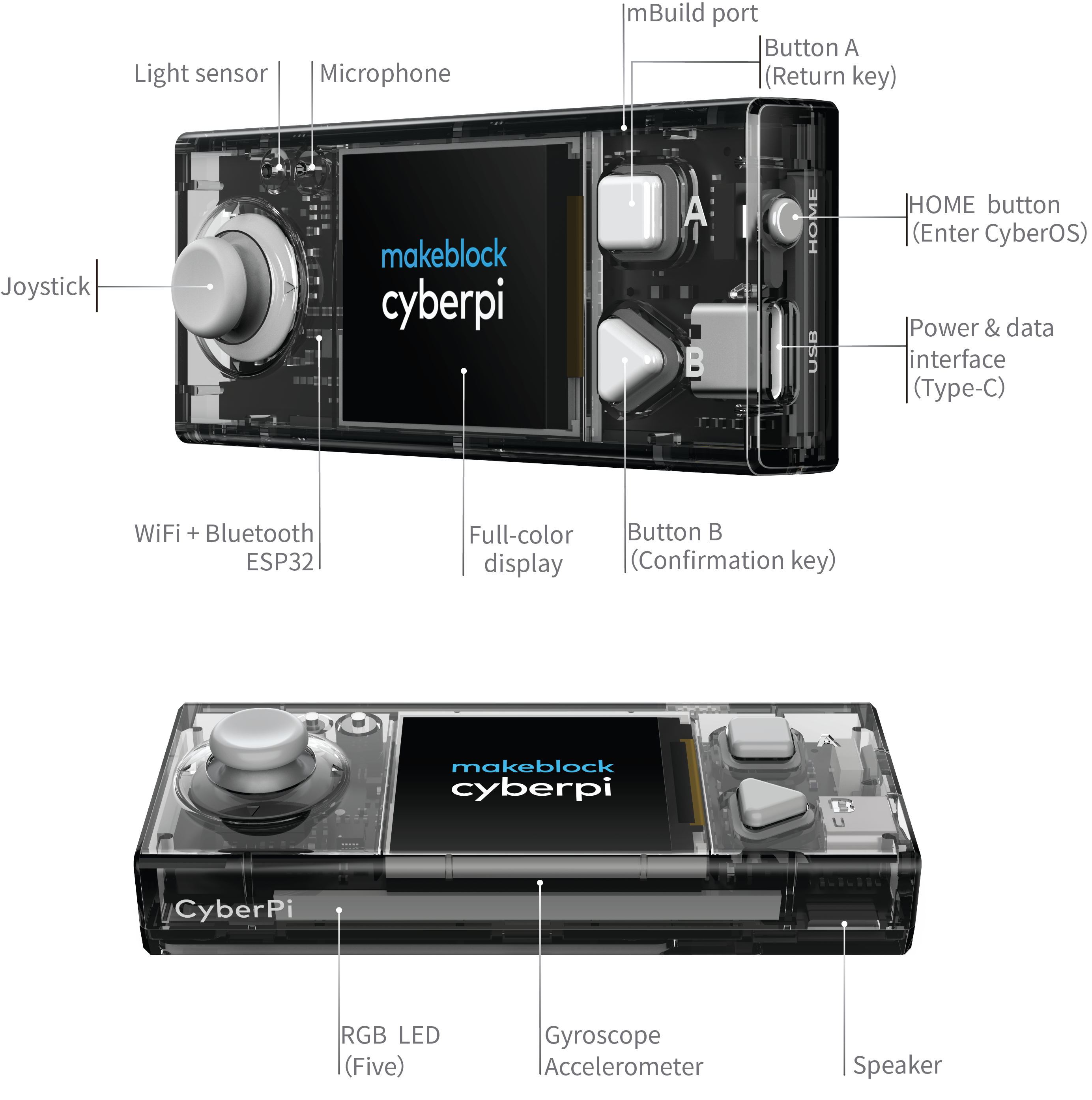
1.2.2 Default functions of the joystick and buttons
CyberPi is equipped with one joystick and two buttons.
On system UIs, the default functions of the joystick and buttons are described as follows.
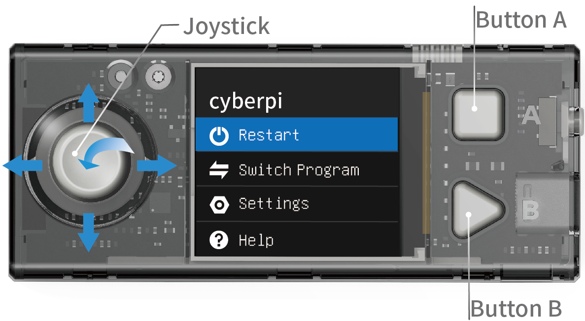
- Move the joystick up: to select the previous item
- Move the joystick down: to select the next item
- **Move the joystick to the left: **to select the left item
- **Move the joystick to the right: **to select the right item
- **Press the joystick in the middle: **to confirm the selection and enter the lower-level menu, if any
- Button A: to return to the upper-level menu
- **Button B: **to confirm the selection and enter the lower-level menu, if any
2. Enter the CyberOS homepage
CyberPi runs CyberOS.
After being powered on, CyberPi displays the system homepage.
If it doesn't display the homepage, you can press the Home button on the right side of CyberPi to enter the homepage.
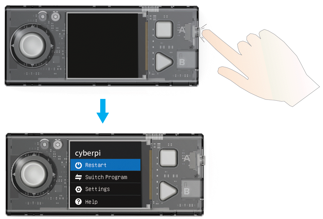 After starting CyberOS, you can use the preset programs, set the system language, and update the system through the Internet.
You can exit from the homepage by choosing "Restart Program", and the system automatically executes the last program you've executed.
:::info **Note: **When CyberPi is connected to mBlock 5 and being programmed in Live mode, the HOME button doesn't take effect and you can't enter the homepage by pressing it. :::
2.2 Set the system language
If the default system language is not your native language, you can change it. The following takes the steps for changing the language from English to Chinese as an example:
(1) Enter the homepage, select Settings by moving the joystick up or down, and press B to enter the Settings page.
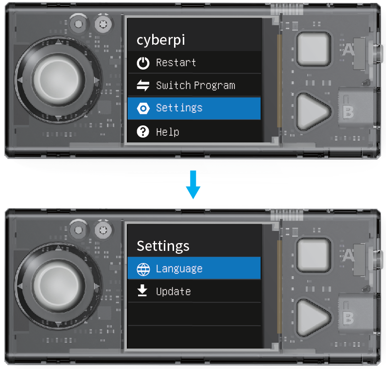 (2) On the Settings page, select Language by moving the joystick up or down and press button B to enter the Language page.
 (3) On the Language page, select 简体中文 by moving the joystick up or down and press button B to complete the setting.
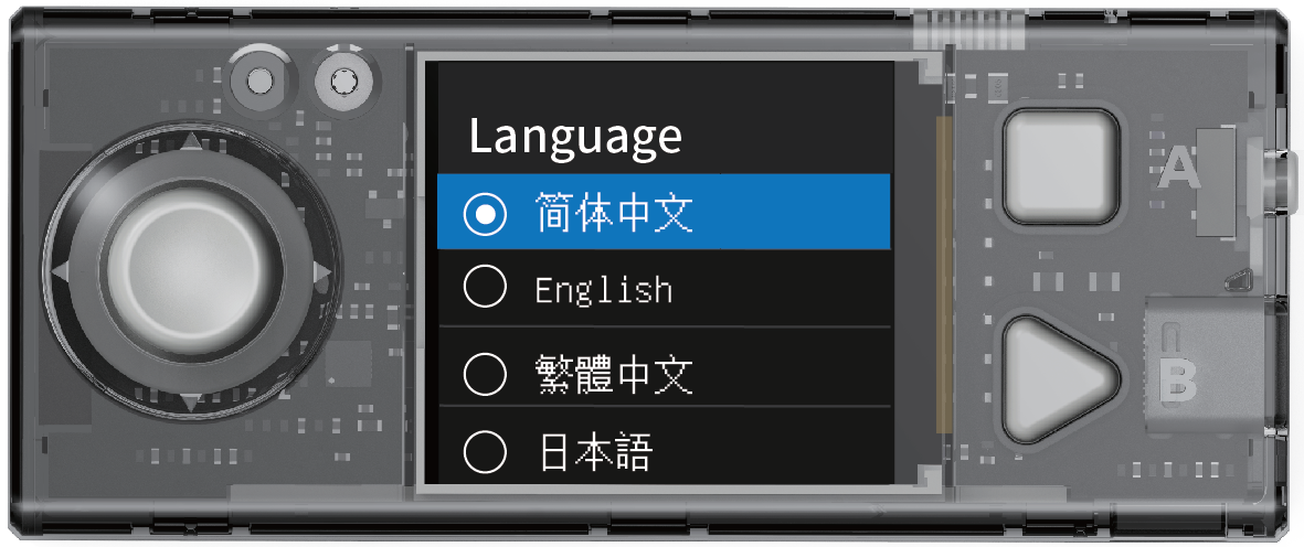 After you set a language, the system switches to the language and returns to the homepage.
2.3 Switch programs
CyberPi can store multiple programs and you can switch them. In addition, CyberPi is delivered with several default example programs on it to help you understand its main functions.
:::info Note:
- Internet access is required for AI and IoT programs, and therefore they are not included in the default example programs and are provided in the example programs on mBlock 5. Find them by choosing Tutorials > Example Programs on mBlock 5.
- The program you upload to CyberPi on mBlock 5 replaces the one you have used last time. The default example programs are provided, and you can restore them by uploading them to your CyberPi. :::
(1) Enter the homepage, select Switch Program by moving the joystick up or down, and press B to enter the Switch Program page.
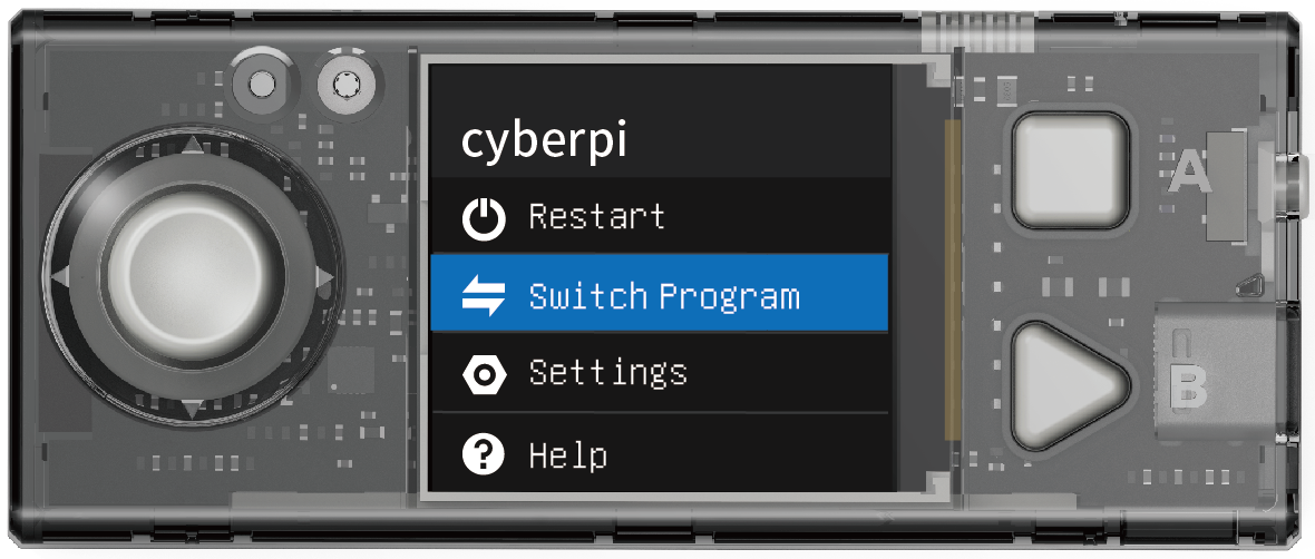 (2) On the Switch Program page, select a program, for example, Program1, by moving the joystick up or down, and then press button B.
CyberPi restarts and executes Program 1.
(2) On the Switch Program page, select a program, for example, Program1, by moving the joystick up or down, and then press button B.
CyberPi restarts and executes Program 1.
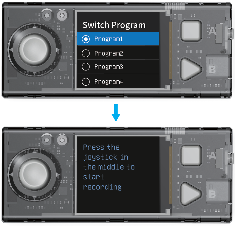 CyberPi displays the name of the program first and then prompts you to perform the steps required for executing the program.
3. Start programming
This section describes how to program CyberPi on mBlock 5. You can use the powerful functions of CyberPi through programming.
3.1 Download and install the required software
Currently, CyberPi supports the block-based graphical programming and Python programming. Make sure that you have downloaded and installed the required software.
| Language | Editor | mBlock 5 version | Required software | URL address |
|---|
|
Scratch, MicroPython |
mBlock Block-based Editor | PC client on Windows/Mac
 | mBlock 5 for Windows
mBlock 5 for Mac | N/A |
| | | Web version on Windows/Mac
 | Google Chrome
mLink2 for Windows
mLink2 for Mac | https://ide.mblock.cc |
| | | Web version on Chromebook
 | mLink for Chromebook
For details about how to use mBlock 5 to program CyberPi on Chromebook, see "Programming CyberPi on Chromebook." | https://ide.mblock.cc |
| Scratch | mBlock Block-based Editor | Mobile app
 | mBlock 5 app | Use your phone or tablet to scan the QR code:
 Alternatively, search for "Makeblock" in app stores. |
| Python, MicroPython | mBlock-Python Editor | Web version on Windows/Mac
Alternatively, search for "Makeblock" in app stores. |
| Python, MicroPython | mBlock-Python Editor | Web version on Windows/Mac
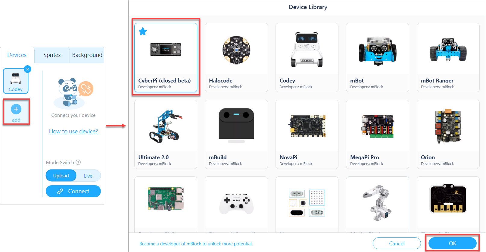 | Google Chrome
mLink2 for Windows mLink2 for Mac | https://python.makeblock.com/ |
3.2 Block-based programming
3.2.1 Add and connect CyberPi
(1) Open mBlock 5.
Open mLink2 if you are to use mBlock 5 on the web.
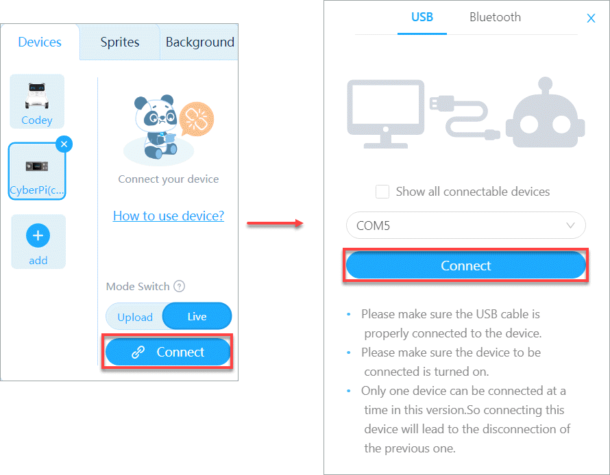 :::info
Note: To use some cloud service functions, you need to sign in to your mBlock 5 account. Sign up an account if you haven't got one.
:::
:::info
Note: To use some cloud service functions, you need to sign in to your mBlock 5 account. Sign up an account if you haven't got one.
:::
(2) Use a Micro USB cable (Type-C) to connect CyberPi to your PC.
 (3) Click + add on the Devices tab, select CyberPi in the device library, and click OK.
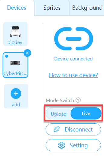 (4) Click Connect to connect CyberPi to mBlock 5.
 A message is displayed after CyberPi is connected, indicating that the connection is successful.
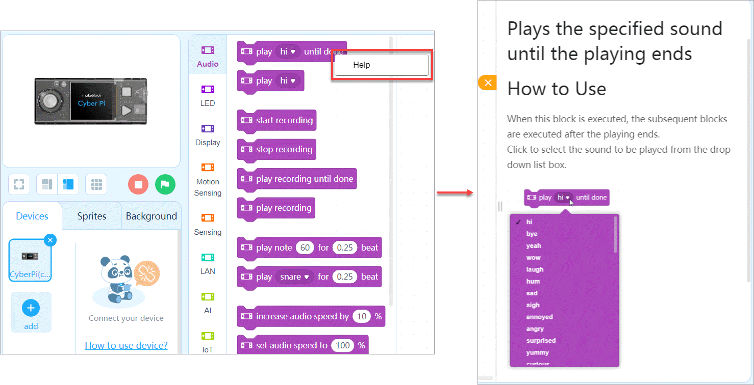 (5) Set the programming mode.
mBlock 5 provides two programming modes, namely Live and Upload. You can click to switch the modes.
(5) Set the programming mode.
mBlock 5 provides two programming modes, namely Live and Upload. You can click to switch the modes.
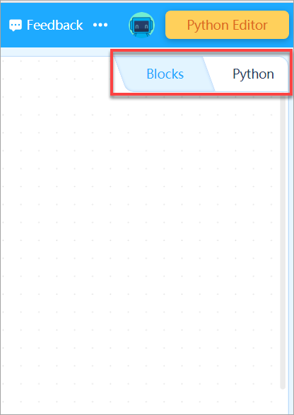 Live: In this mode, you can view the program execution effect in real time, which facilitates the debugging of the program. In this mode, you must keep CyberPi connected to mBlock 5. If they are disconnected, the program cannot be executed.
Upload: In this mode, you need to upload the compiled program to CyberPi. After being successfully uploaded, the program can still run properly on CyberPi when it is disconnected from mBlock 5.
Live: In this mode, you can view the program execution effect in real time, which facilitates the debugging of the program. In this mode, you must keep CyberPi connected to mBlock 5. If they are disconnected, the program cannot be executed.
Upload: In this mode, you need to upload the compiled program to CyberPi. After being successfully uploaded, the program can still run properly on CyberPi when it is disconnected from mBlock 5.
3.2.2 Example programs
mBlock 5 provides a large number of example programs.
Choose Tutorials > Example Programs and click CyberPi to view example programs provided for CyberPi.
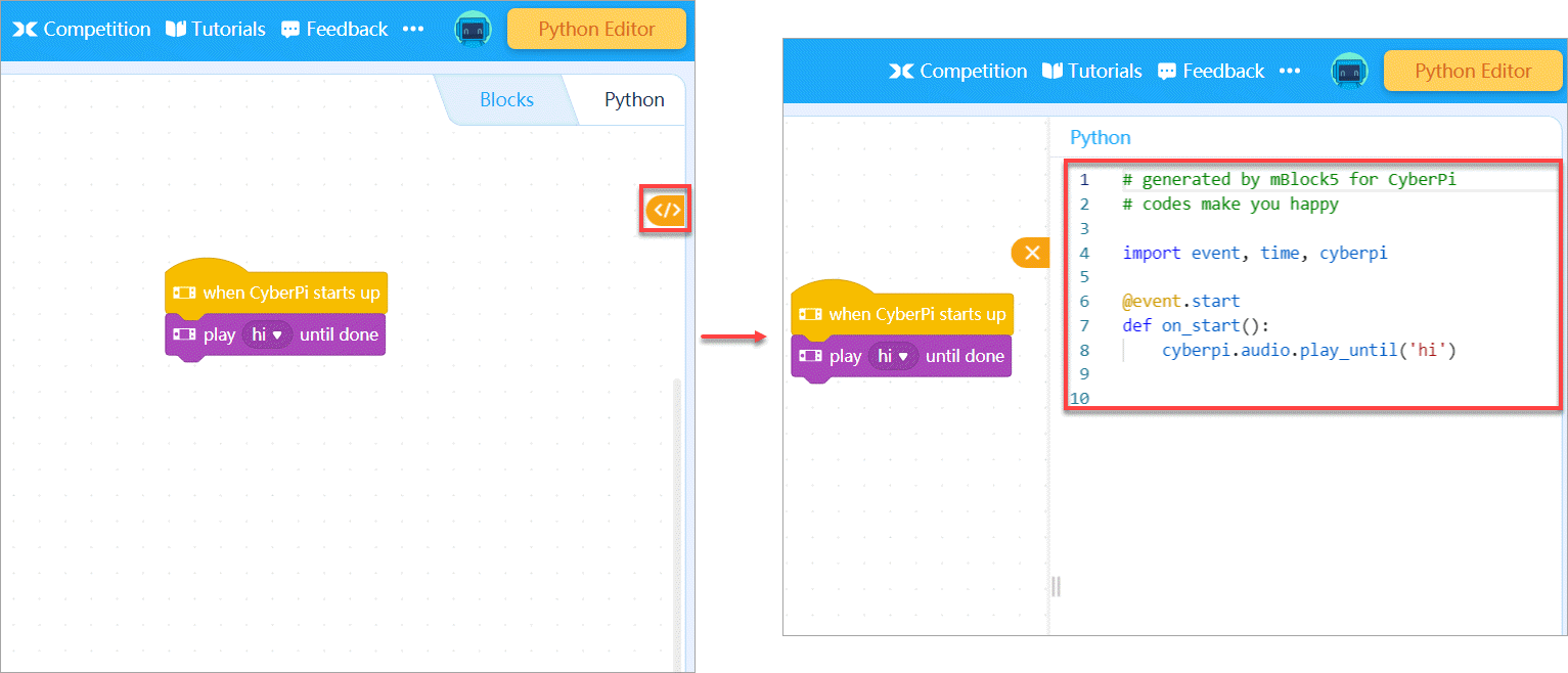
You can select and load a program to view, execute, or upload it to CyberPi.
3.2.3 Block help
mBlock 5 provides multiple types of blocks for CyberPi. If you don't understand a block when using it, you can right-click it and click Help that appears.
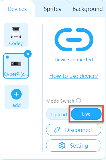
3.2.4 Programming languages
mBlock 5 provides two programming languages for CyberPi, namely block-based programming and Python. In Upload mode, you can click the buttons on the right to switch the programming languages.
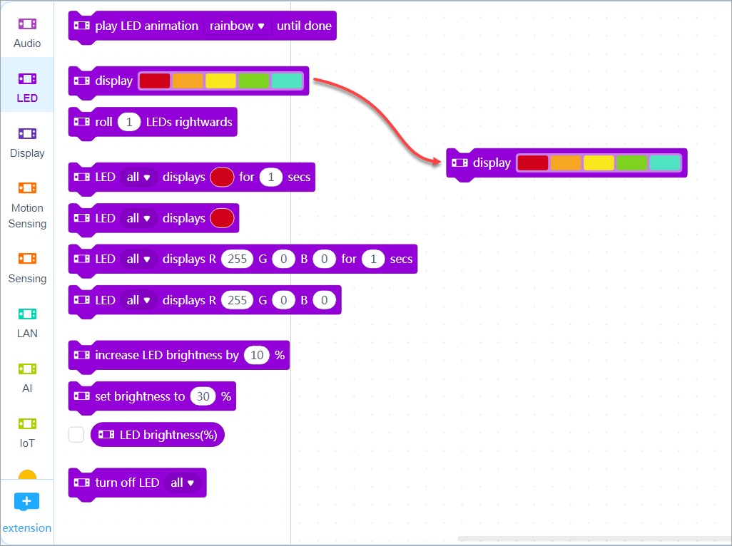 In addition, when programming CyberPi in the block-based language, you can click the switching button on the right to view the corresponding Python statements (obtained by converting the blocks).
 :::tips
Note: You can see Python API Documentation for CyberPi to know about more functions of CyberPi.
:::
:::tips
Note: You can see Python API Documentation for CyberPi to know about more functions of CyberPi.
:::
3.2.5 Example: Compile the “Marquee” program
Perform the following steps to compile a program using blocks in Live mode to implement the marquee effect of the LEDs on CyberPi.
(1) Set the programming mode to Live.
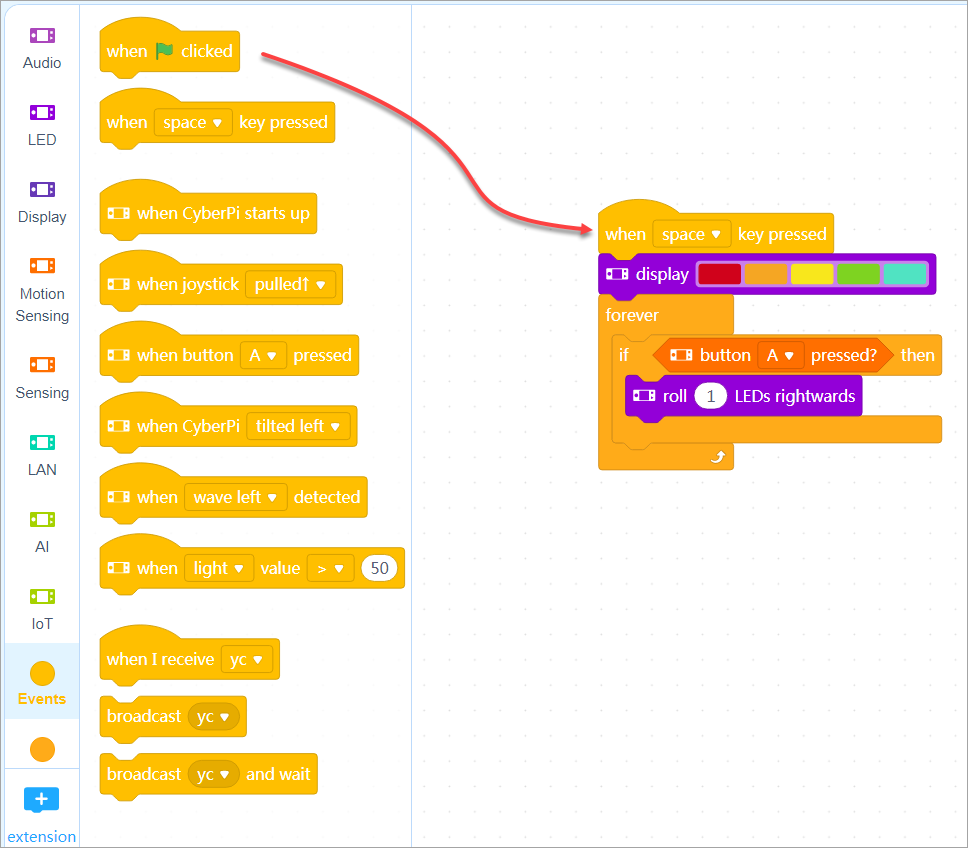 (2) Set the initial color(s) of the LEDs.
 Set the initial colors to red, orange, yellow, green, and cyan.
(3) Set a condition for rolling the colors.
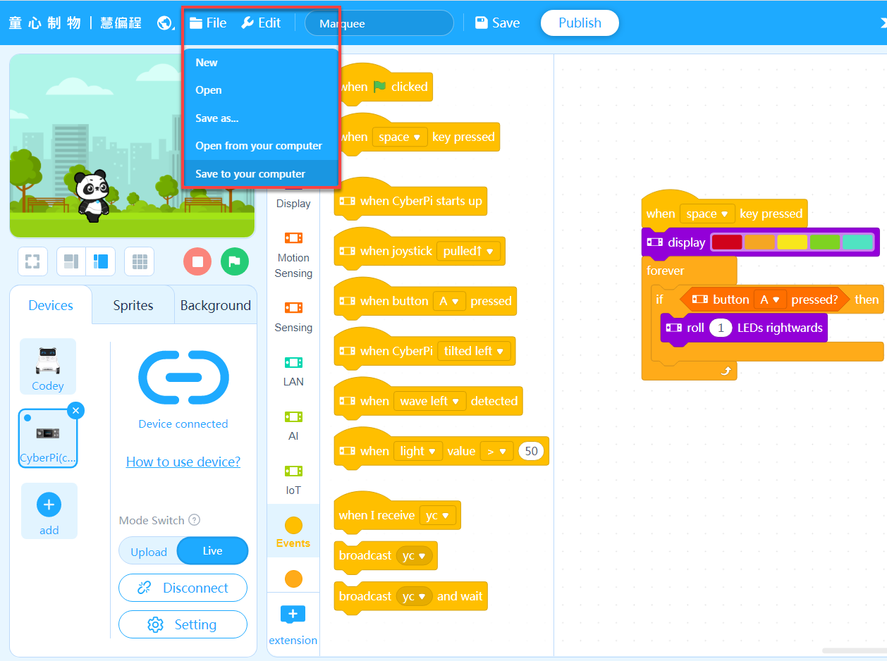 Each time button A on CyberPi is pressed, the colors roll from left to right by one position.
(4) Add an event that triggers the program.
The program is to be executed when you press the space key.
**The Marquee program is complete. **
Press the space key, and then keep pressing button A to see the execution result of the program.
(5) Name the project and save it.
After saving a project, you can click your user image and choose My Projects to view it.
:::info ** Note:** To save projects, you need to sign in to mBlock 5 first. :::
You can also save your project to the local disk.
3.3 Python programming
Open mBlock-Python Editor on Google Chrome. For details about how to program CyberPi on mBlock-Python Editor, see mBlock-Python Editor Online Help.
4. Online help
After-sales services and technical support
If you encounter any product quality problems or find any parts missing or damaged when you open the package, or if you need any technical support, contact us for after-sales services through:** ** support@makeblock.com (Service hours: 9:00–12:00 & 14:00–18:30 from Monday to Friday)
Feedback and suggestions
Should you have any feedback or suggestions on CyberPi, contact our R&D team through: cyber.list@makeblock.com
5. FAQs
How can I design a game with CyberPi?
To ensure user experience, only limited control permission on CyberPi's screen is provided for users currently. More functions are on the way.
Currently, you can use mBlock-Python Editor in combination with some Python libraries such as pygame to implement control over a Python game, using CyberPi as a remote control.
You can find examples in the mBlock-Python Editor Online Help.
Alternatively, you can use the CyberPi Lab extensions to use the latest functions of CyberPi, for which you may need to update the firmware of CyberPi.
6. More information
CyberPi Operation Guide Pocket Shield Operation Guide CyberPi Series User Manual Python API Documentation for CyberPi mBlock 5 Online Help mBlock-Python Editor Online Help
Introductionto mBot2
[Detailed Example] Programming mBot2 with the Mobile mBlock 5 App
This page describes how to write a simple obstacle avoidance program for mBot2 with the mBlock 5 app on your smart device.
Before you start, make sure that you've got:
| 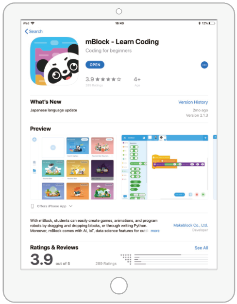 or
or  A tablet or smart phone |
 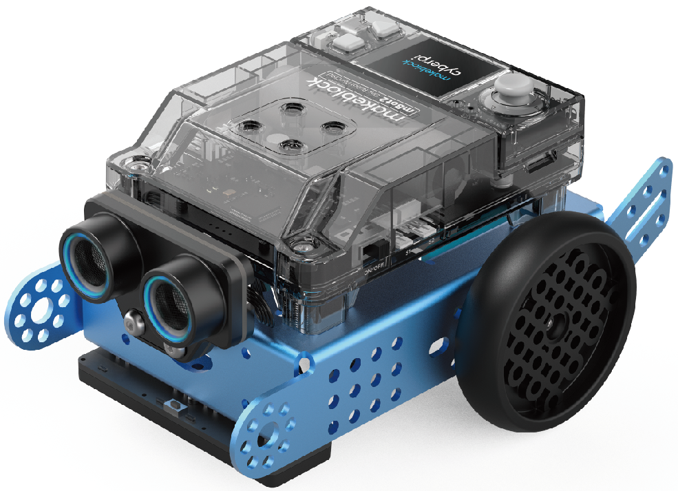 mBot2
If you haven't completed the building of mBot2, refer to "Build mBot2" to build it first. |
| --- | --- |
mBot2
If you haven't completed the building of mBot2, refer to "Build mBot2" to build it first. |
| --- | --- |
:::info Note: The smart device described on this page is a tablet, and you can use the mBlock 5 app on smart phones in the same way. :::
1. Download the mBlock 5 app on the tablet
(Skip this step if you have already downloaded the mBlock 5 app.)
Use the tablet to scan the following QR code:
 Alternatively, search for mBlock in app stores to download it.
2. Connect mBot2 to the mBlock 5 app
(1) Enable the Bluetooth function on the tablet.
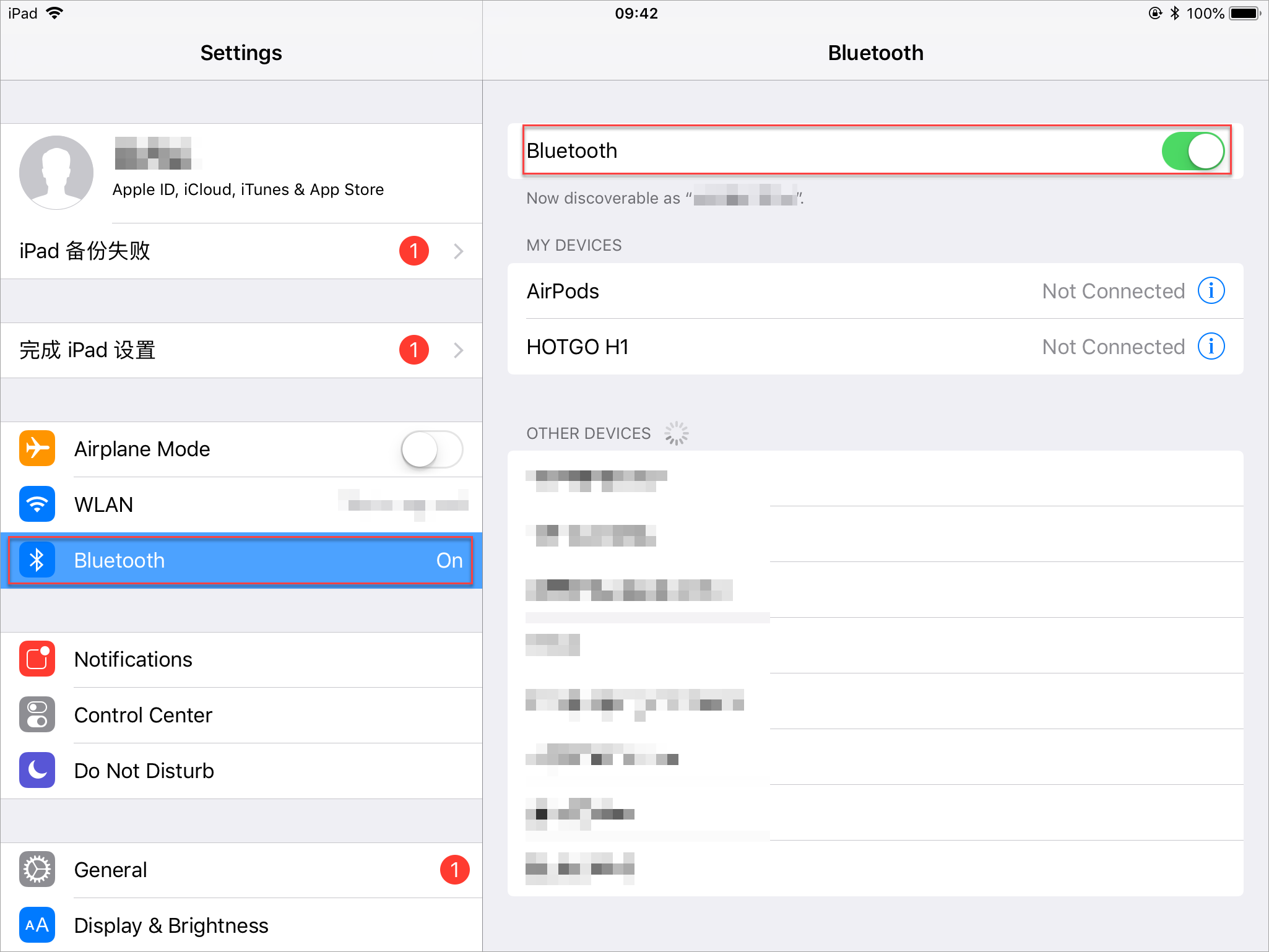
(2) Power on mBot2.
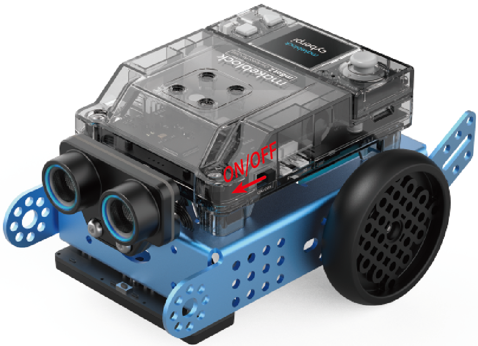
(3) Tap to open the mBlock 5 app.

(4) Tap "Coding", and tap "+" on the page that appears.
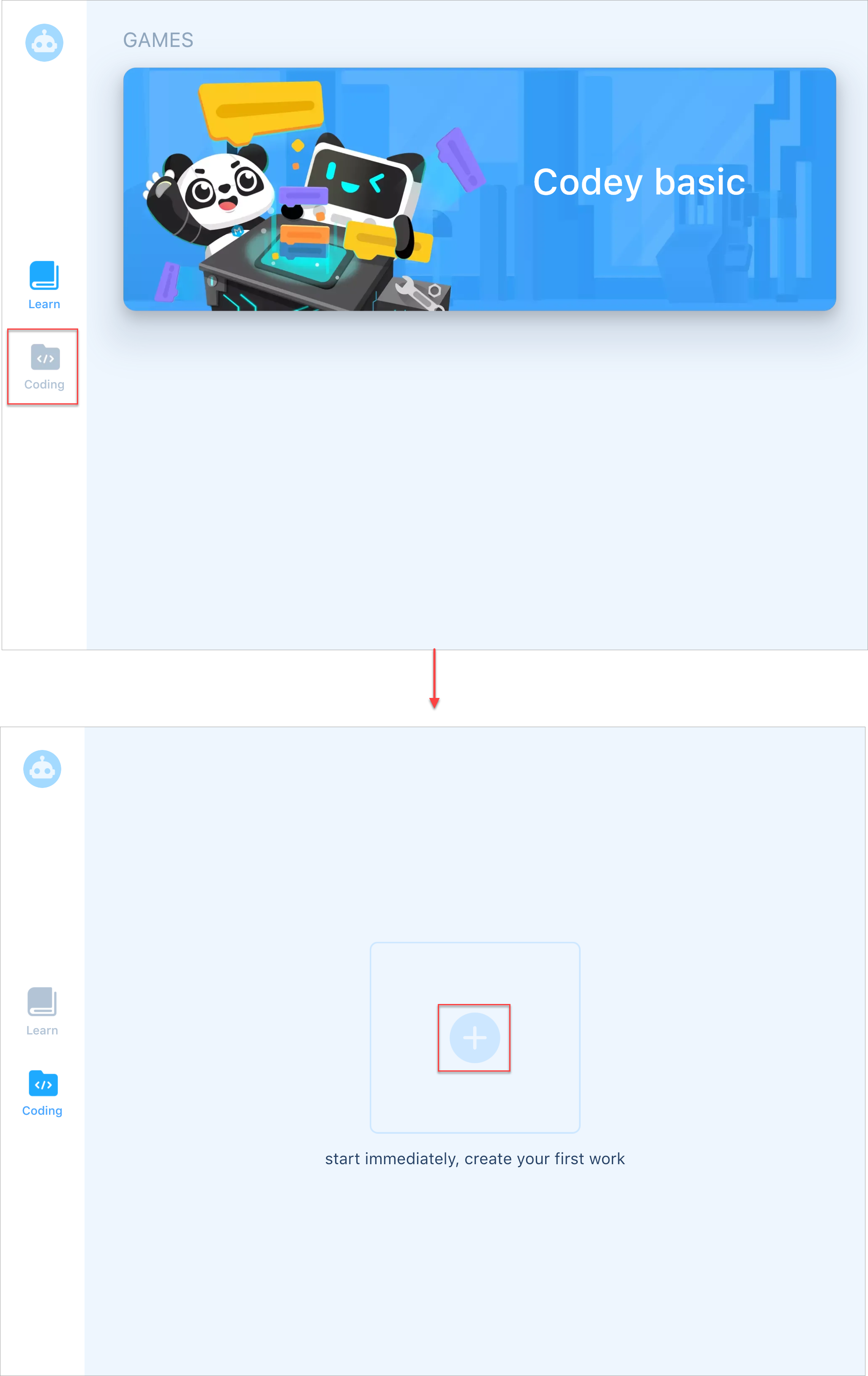
(5) In the sprite library, choose "Devices" > "CyberPi" and tap "√".
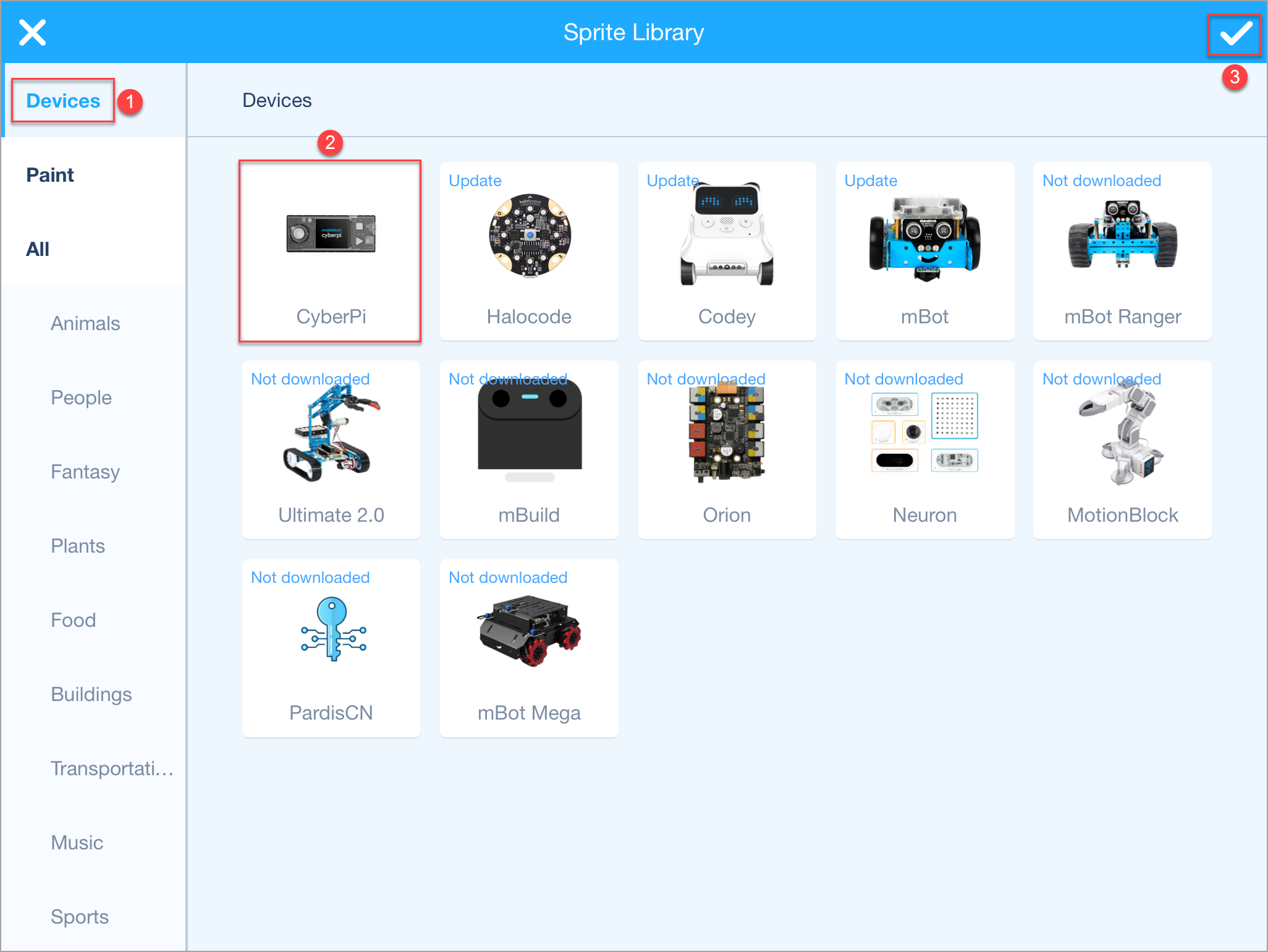
(6) Tap the CyberPi setting icon and then tap "Connect" on the device setting page that appears.
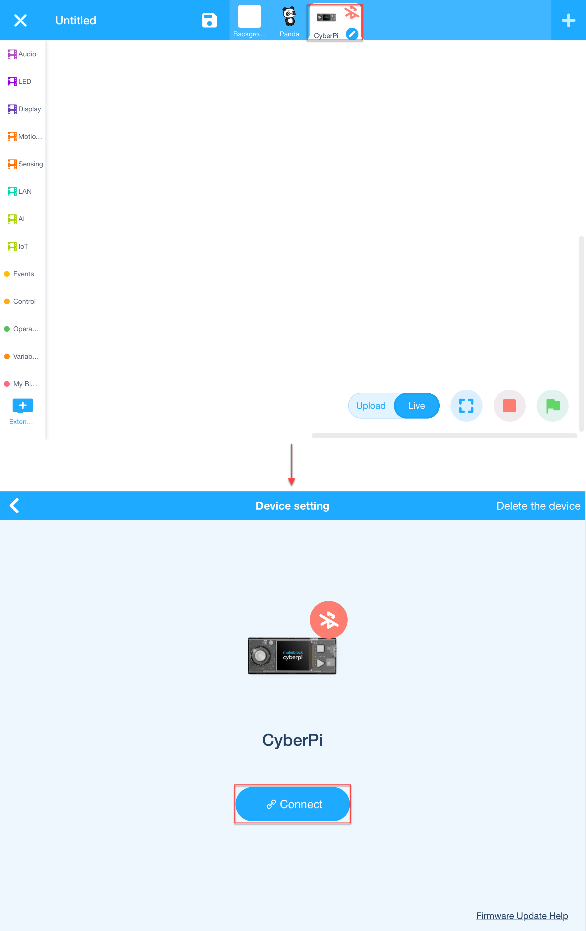
(7) Place the tablet close to mBot2.
mBlock 5 automatically searches for and connects to mBot2.
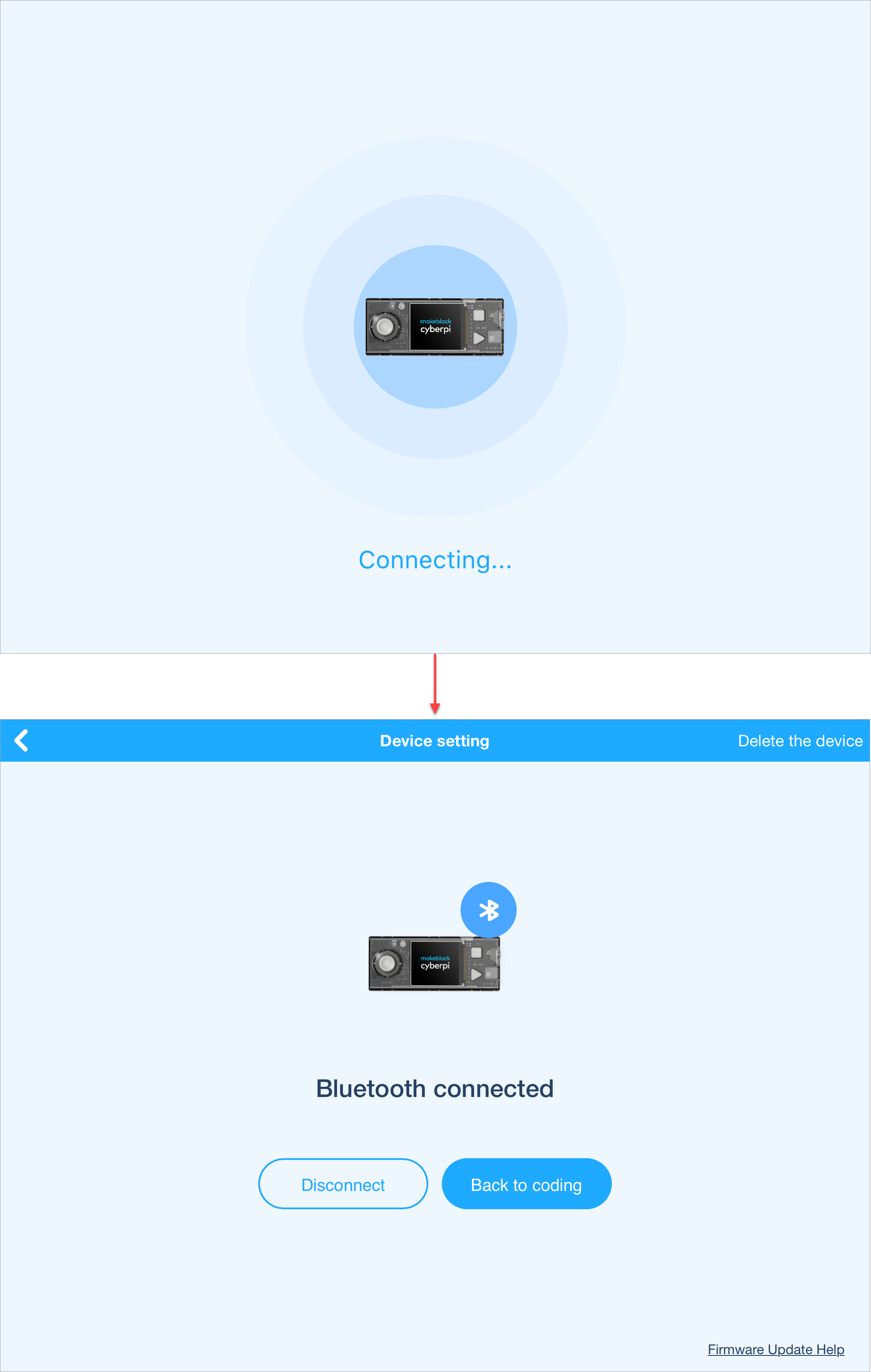 After the connection is complete, a voice message is played, indicating that the connection is successful.
3. Start to write the program
(1) Tap "Back to coding".
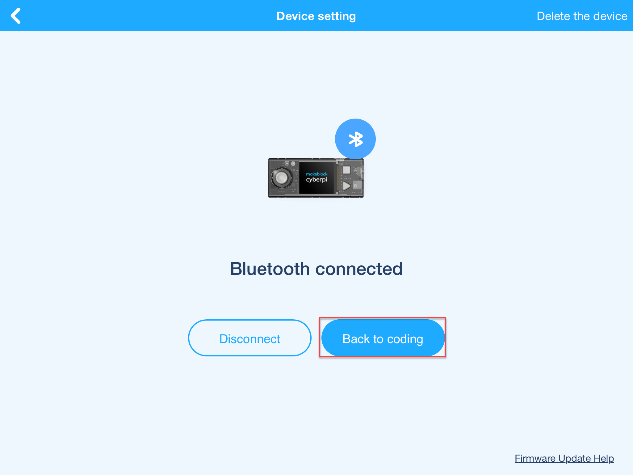
(2) Add the extensions required in the obstacle avoidance program.
To avoid obstacles, mBot2 uses its ultrasonic sensor 2 to detect obstacles in its way and then respond to them by using the motors and wheels connected to mBot2 Shield. Therefore, you need to add the mBot2 and Ultrasonic Sensor 2 extensions.
Add them as follows:
a. Tap + Extension at the bottom of the blocks area, and then tap + Add under mBot2 on the Extension Center page that appears.
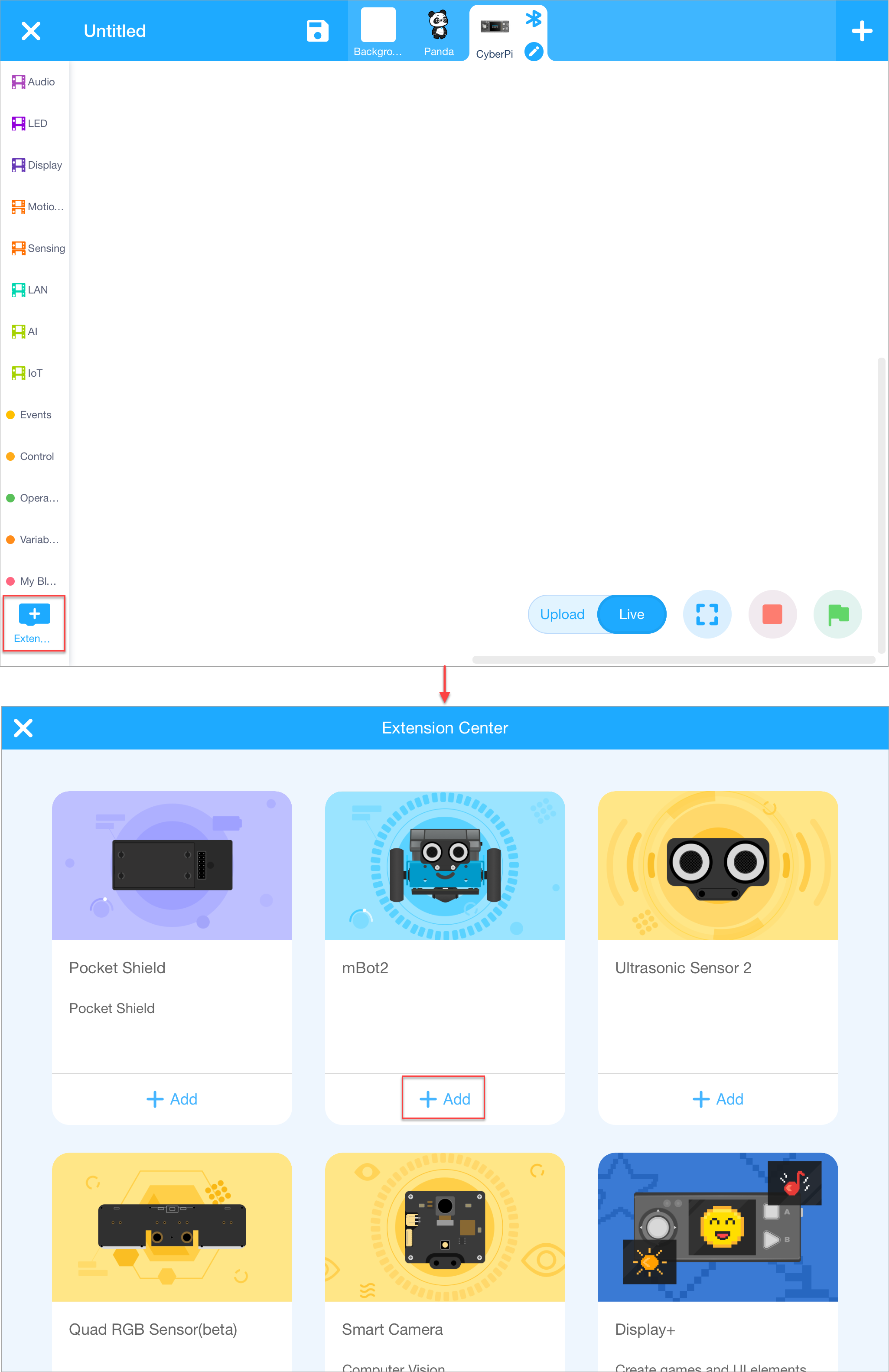 b. Tap + Extension at the bottom of the blocks area, and then tap + Add under Ultrasonic Sensor 2 on the Extension Center page that appears.
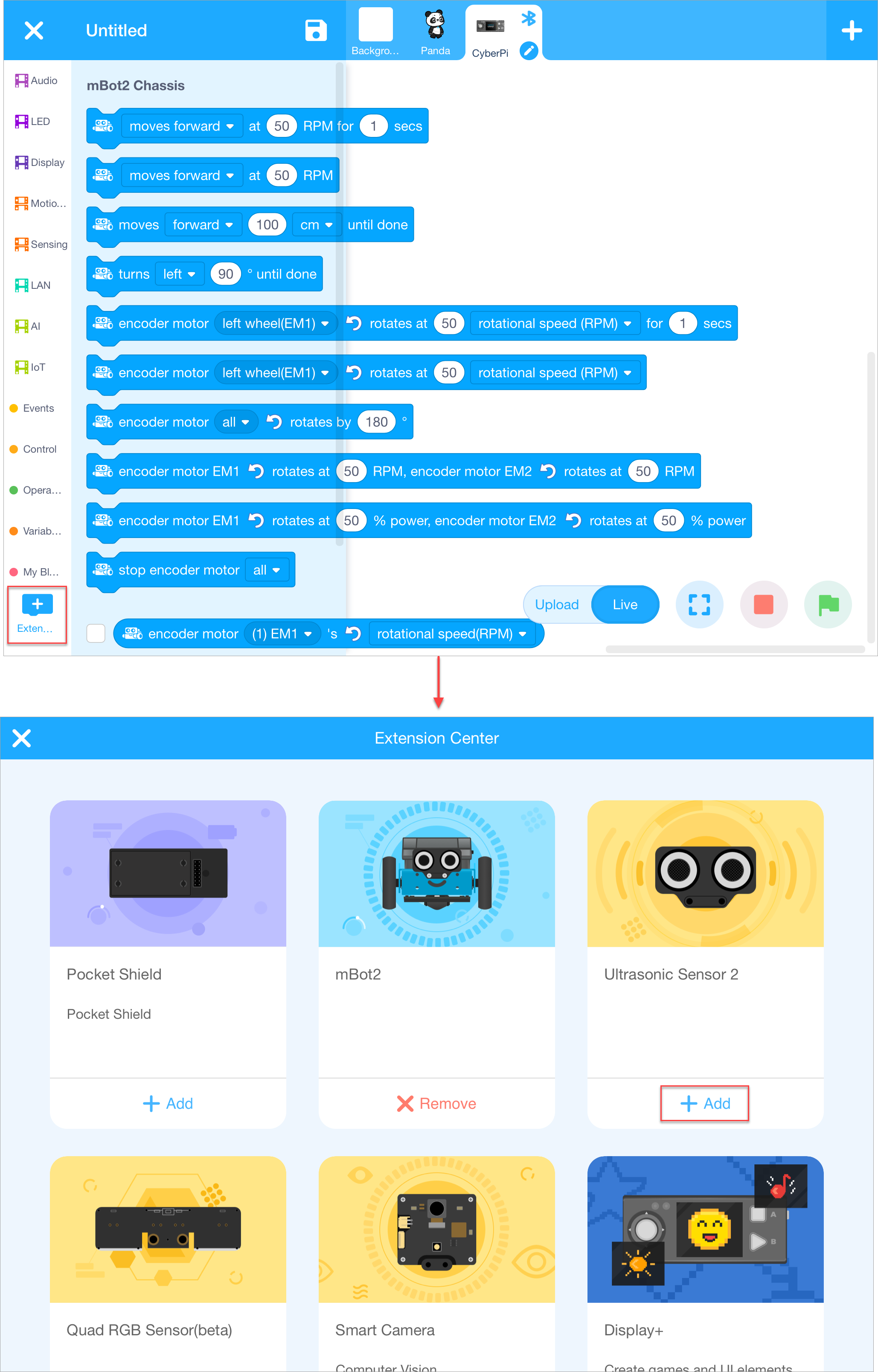 After the extensions are added, you can find the blocks in the blocks area.
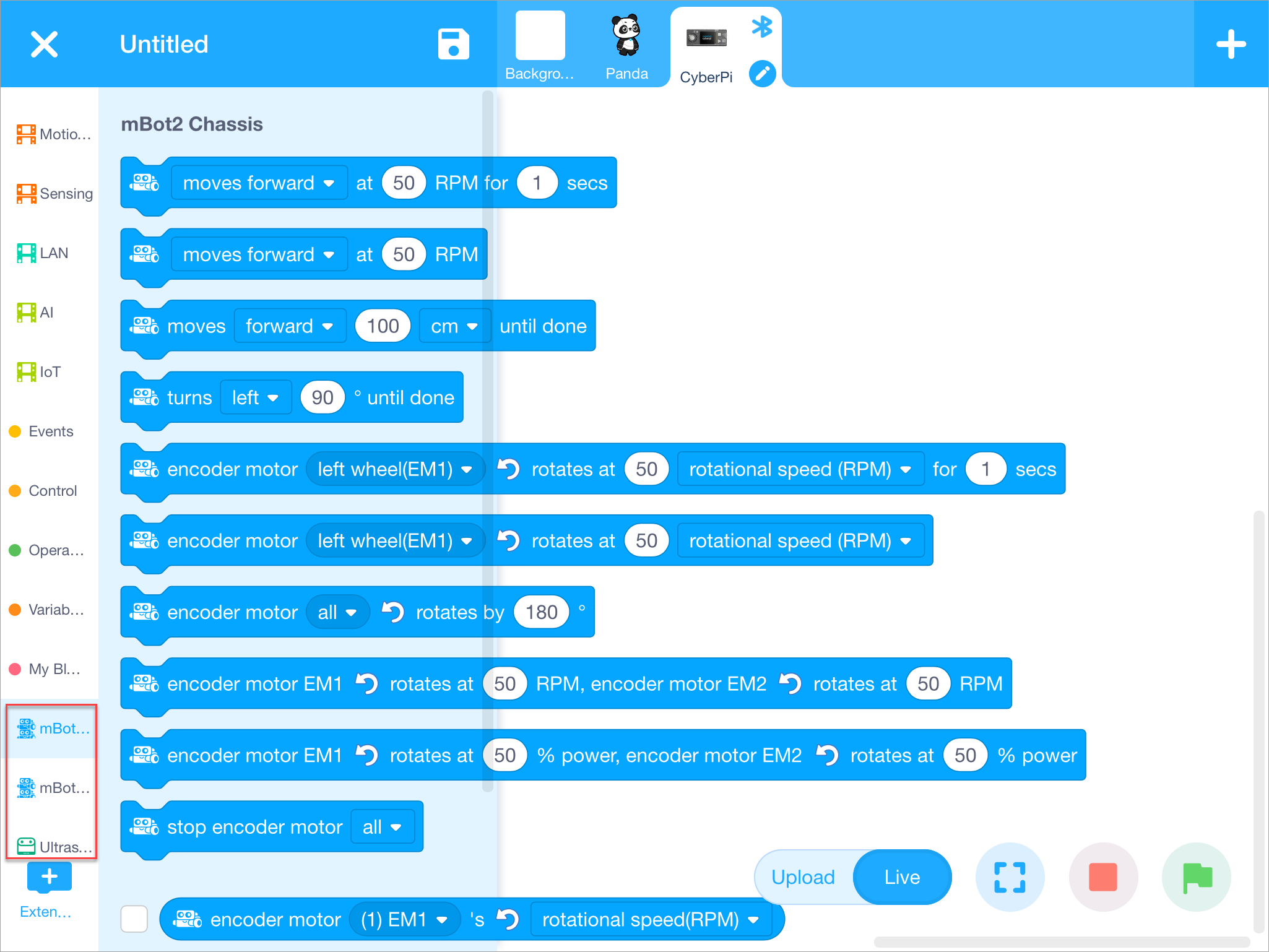
(3) Set the programming mode to "Upload".
Live: In this mode, you can view the program execution effect in real time, which facilitates the debugging of the program. In this mode, you must keep mBot2 connected to mBlock 5. If they are disconnected, the program cannot be executed.
Upload: In this mode, you need to upload the compiled program to mBot2. After being successfully uploaded, the program can still run properly on mBot2 when it is disconnected from mBlock 5.
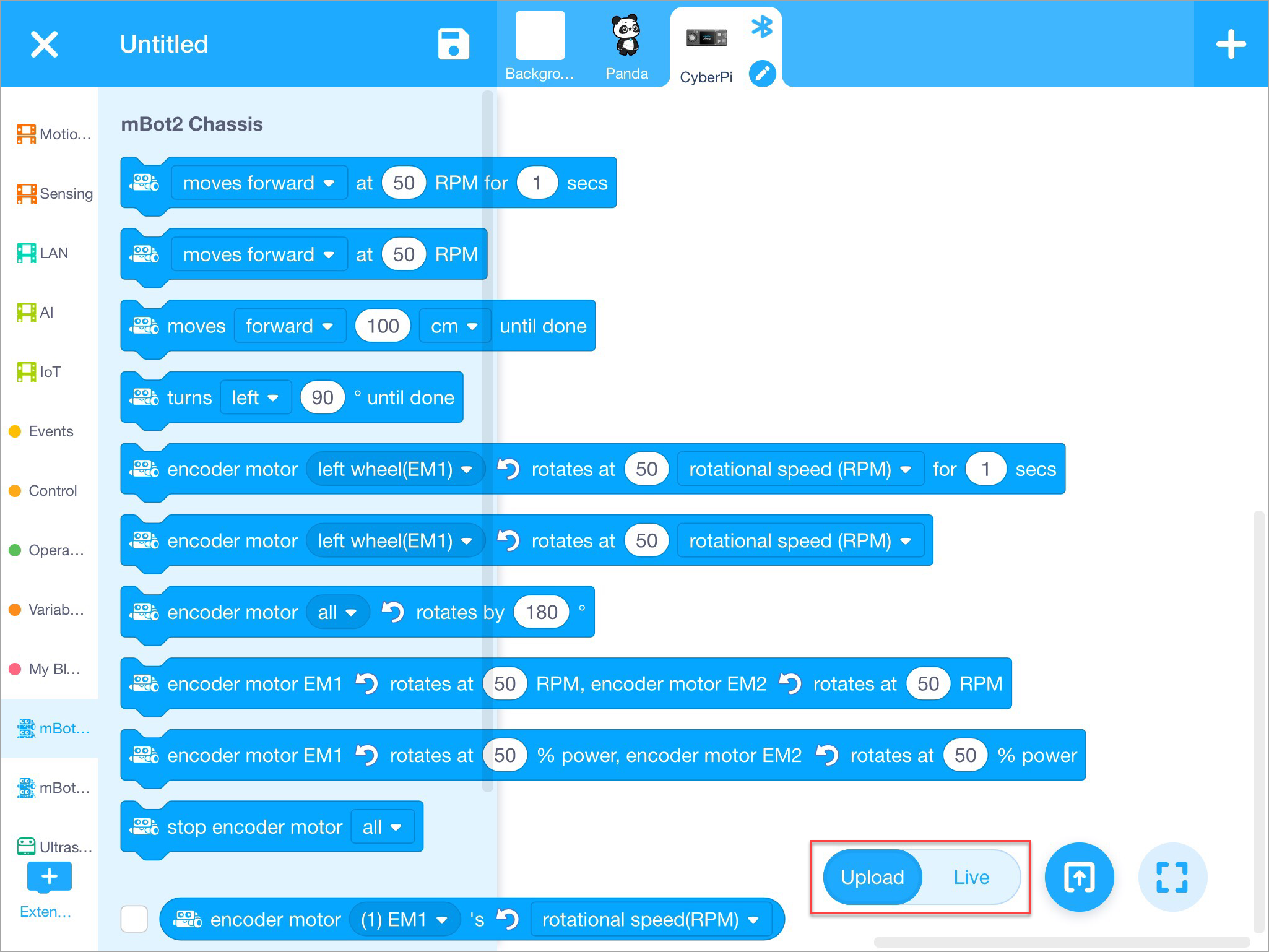
(4) Drag the blocks required to the scripts area.
a. First, define the event for triggering the execution of the obstacle avoidance program. For example, trigger the program by pressing button B.
Tap the Events category, drag the block when button () pressed to the scripts area, and tap the drop-down list box to select button B.
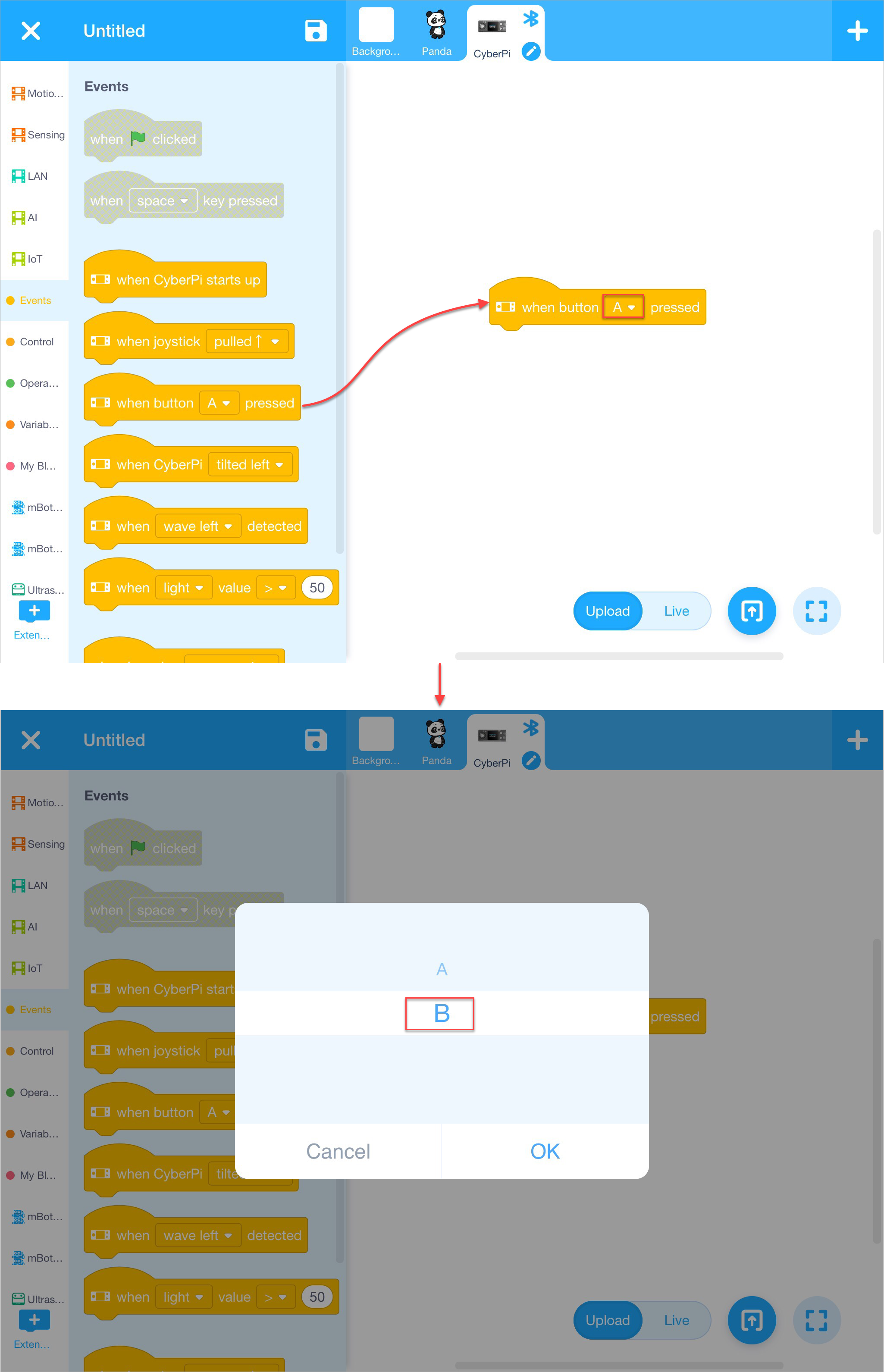
b. Define how many times the program is to be executed. For example, keep executing the program after it is triggered.
Tap the Control category and drag the block forever to the scripts area.
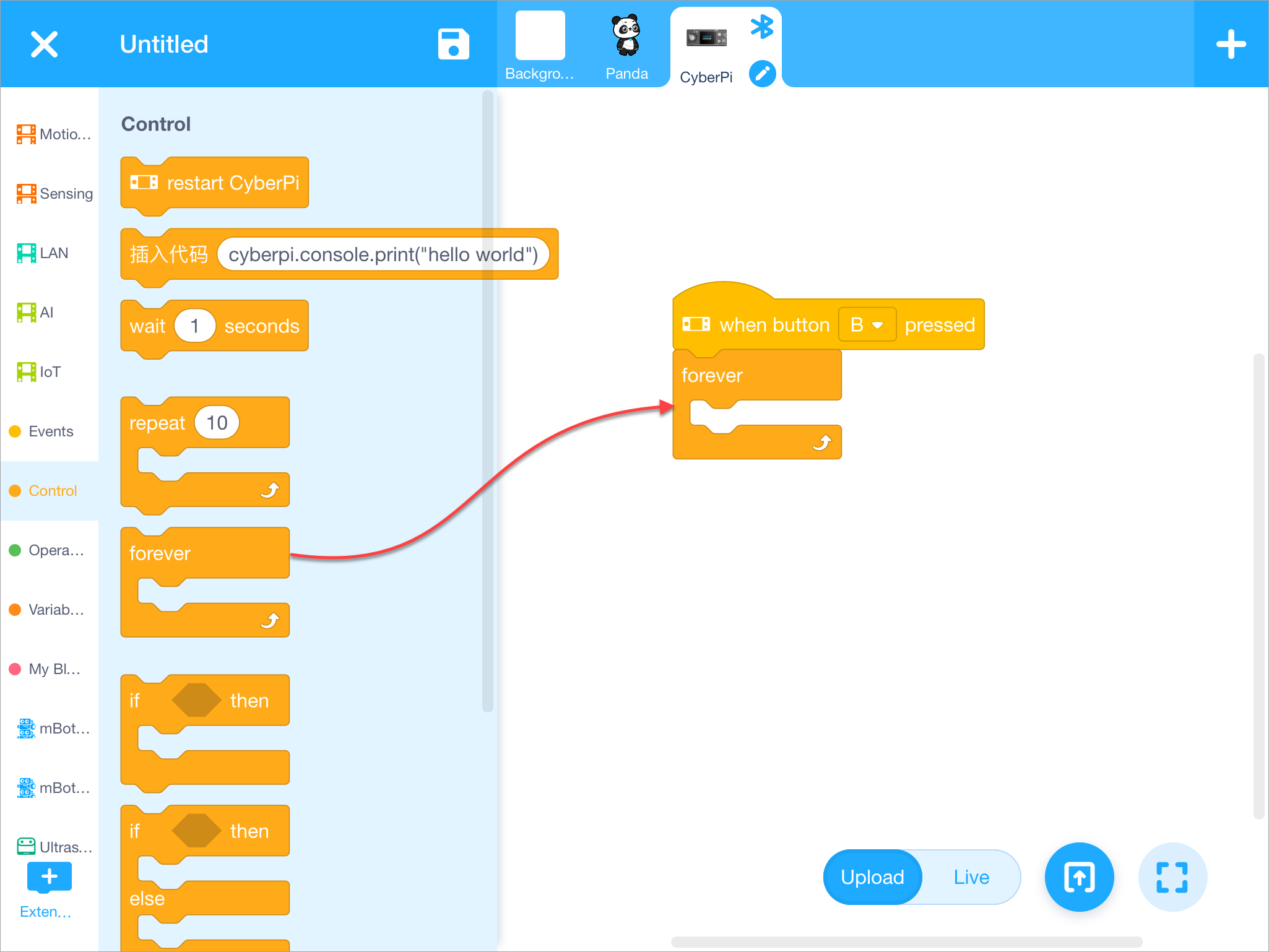
c. Define the specific conditions for avoidance and how mBot2 responds to an obstacle.
Define the condition For example, mBot2 starts to avoid an obstacle when it is 9cm or less away from mBot2; and mBot2 keeps moving forward when no obstacle is found or an obstacle is more than 9cm away from it.
Tap the Control category and drag the block if () then () else () to the scripts area.
The condition involves the operation of distance.
Tap the Operators category and drag the block () > () to the scripts area and put it into the condition block.
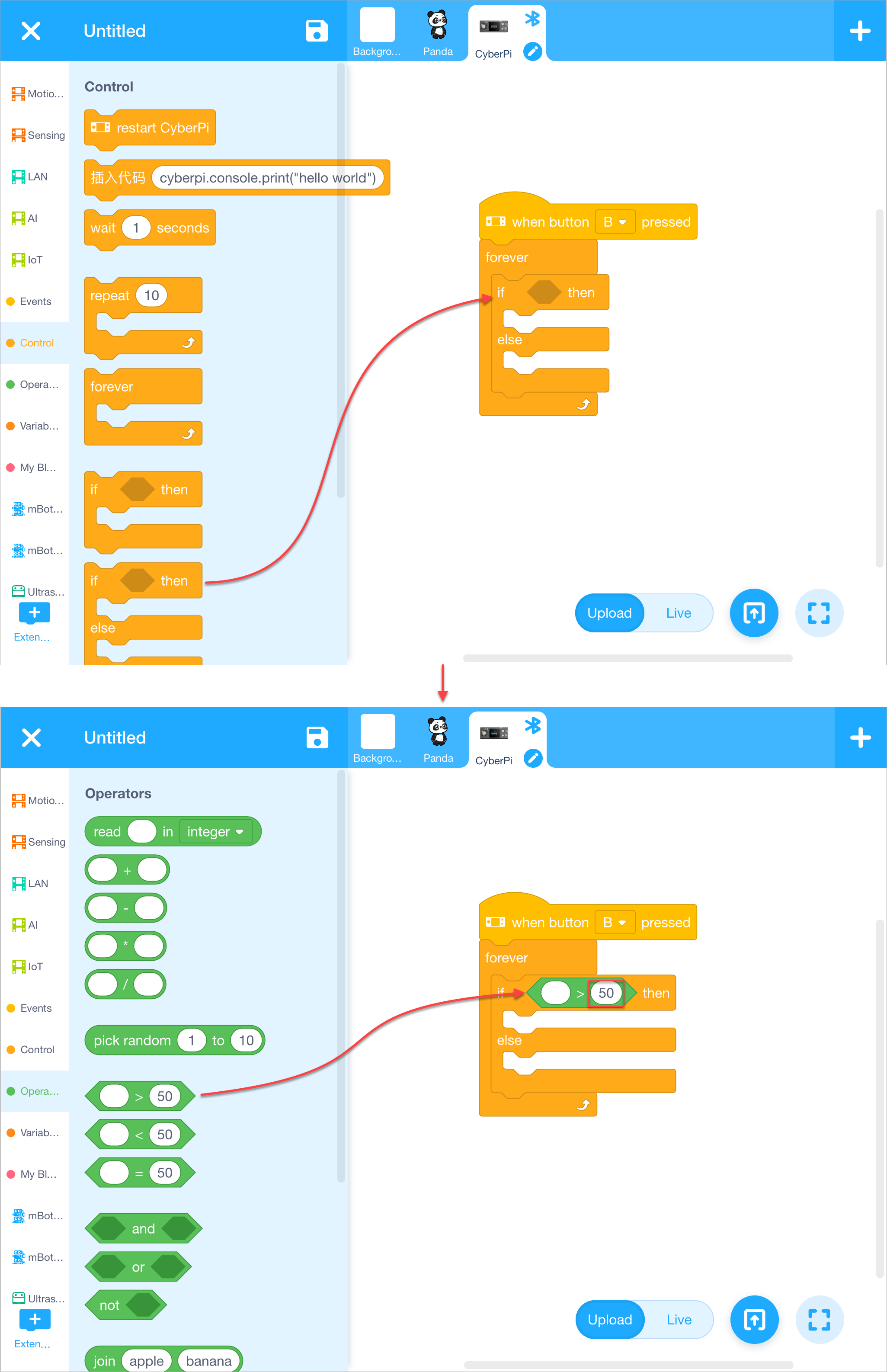 Tap the value 50 to change it to 9.
Tap the Ultrasonic Sensor 2 category and drag the block ultrasonic 2 () distance to an object (cm) to the scripts area and put it into the operation block.
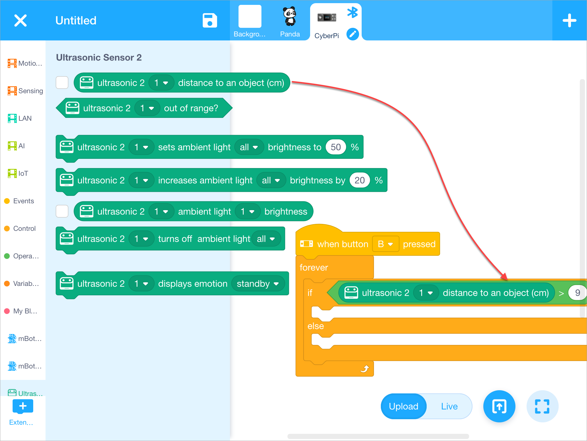
Define the responses
When an obstacle is more than 9cm away from mBot2, mBot2 keeps moving forward.
Tap the mBot2 Chassis category and drag the block () at () RPM to the scripts area and put it into the condition block.
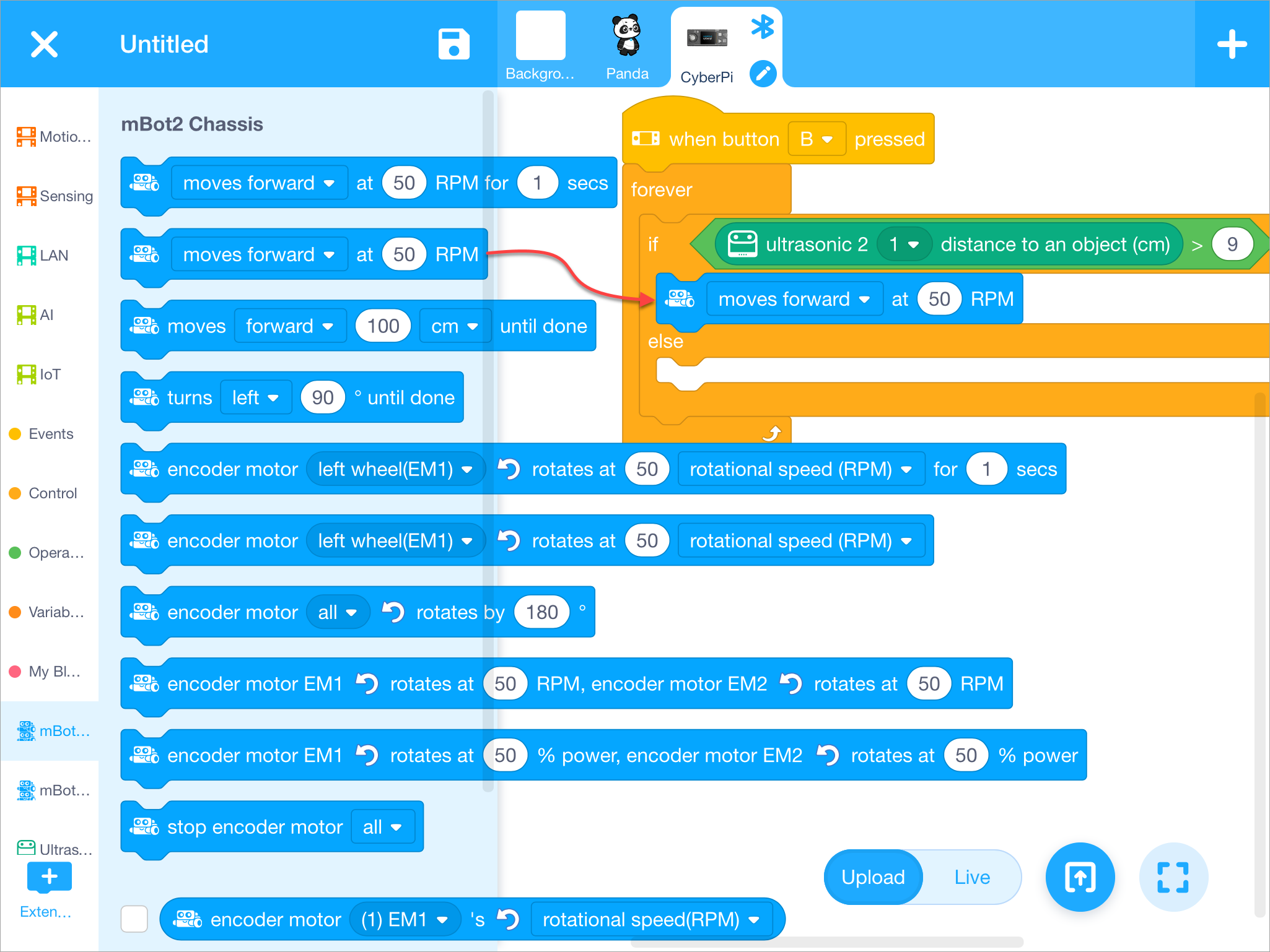
When an obstacle is 9cm or less away from mBot2, mBot2 turns left.
Drag the block () at () RPM for () secs to the scripts area, put it into the condition block, and tap the drop-down list box to select turns left.
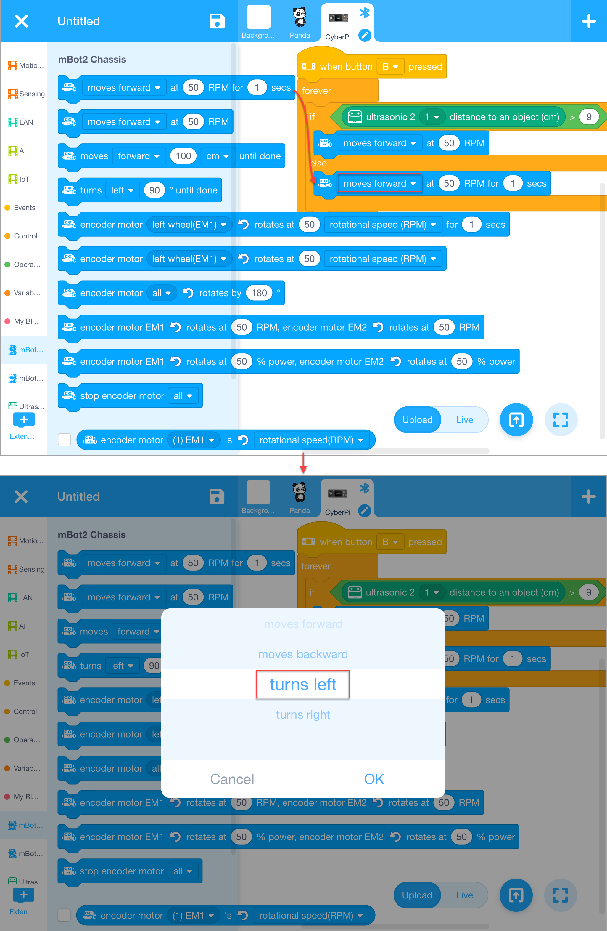
Now, a simple obstacle avoidance program is completed.
4. Upload the program to mBot2
:::info Note: The program you upload will replace the last program you execute on mBot2. :::
Tap the Upload icon, wait till the uploading is complete, and tap OK.
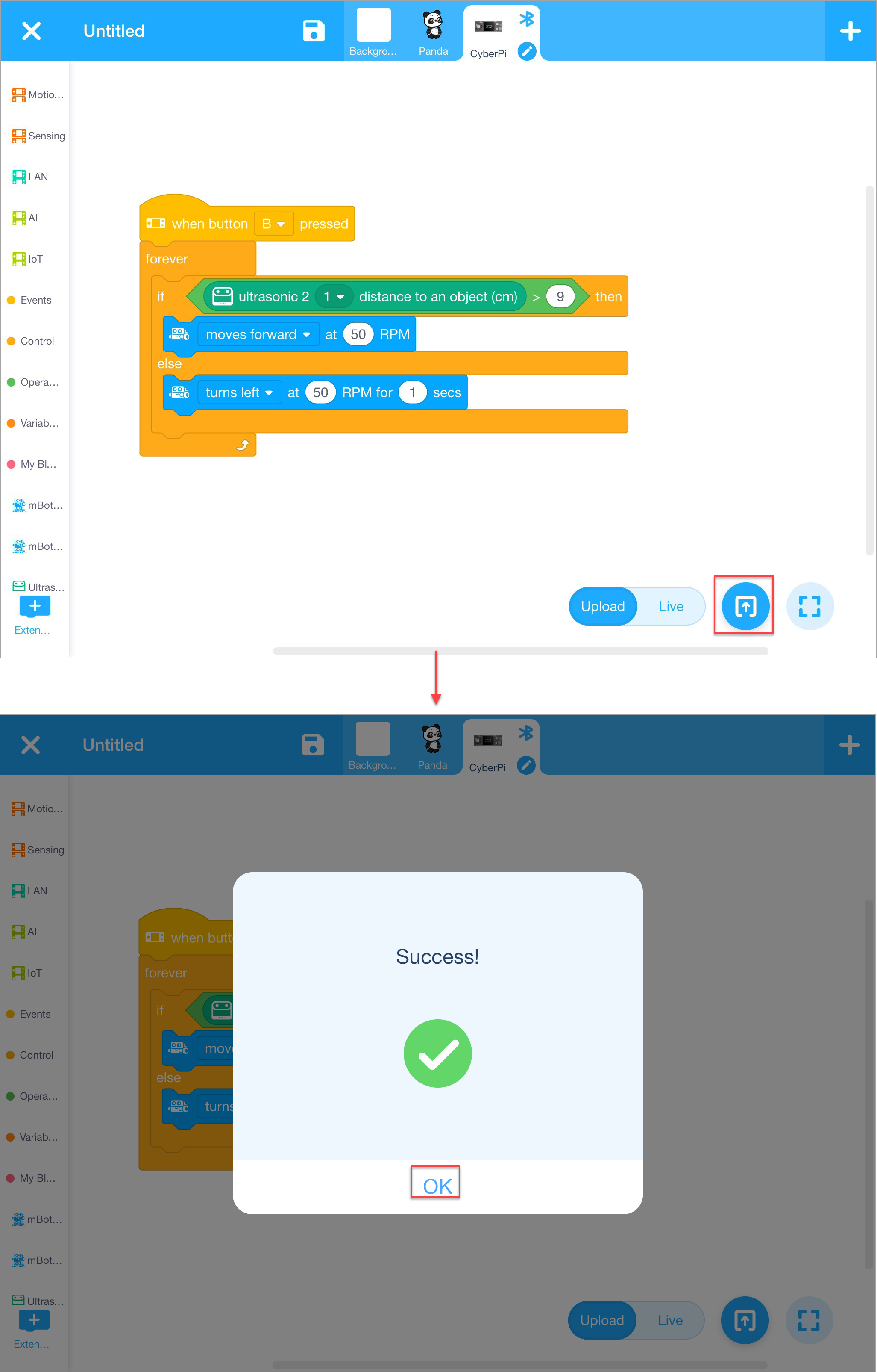
5. Execute the program
Press button B on CyberPi.
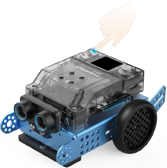 mBot2 starts to move forward and detects obstacles. When an obstacle is found and it's 9cm or less away from mBot2, mBot2 turns left for one second and then moves forward.
:::tips Tips:
- You can change the parameter values on the blocks (such as changing the distance threshold or responses) or add more conditions to compile your own obstacle avoidance programs.
- You can also compile other programs (such as a line following program) in a similar way. :::
[Detailed Example] Program mBot2 with mBlock 5 on Your PC
This page describes how to write a simple obstacle avoidance program for mBot2 with the mBlock 5 client on your PC.
Before you start, make sure that you've got:
| 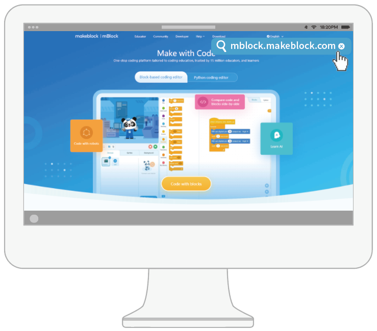 or
or 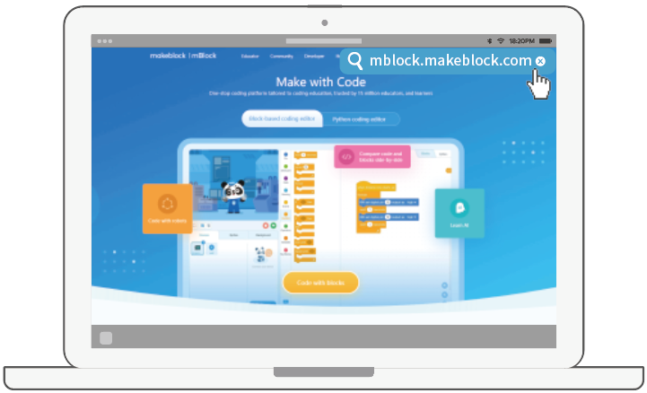 A computer |
  mBot2
If you haven't completed the building of mBot2, refer to "Build mBot2" to build it first. |
| --- | --- |
mBot2
If you haven't completed the building of mBot2, refer to "Build mBot2" to build it first. |
| --- | --- |
1. Download and install mBlock 5 on your PC
(Skip this step if you have already downloaded and installed mBlock 5 on your PC.)
(1) Go to https://mblock.makeblock.com/en-us/download/ to download mBlock 5 to a local disk.
 Download the version compatible to the system running on your PC.
(2) Double-click the software you've downloaded to install it.
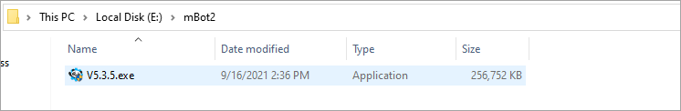 Click Yes when the system asks you "Do you want to aloow this app to make changes to your device?" and click to install drivers if prompted.
2. Connect mBot2 to mBlock 5
(1) Double-click the mBlock 5 icon on your PC to open it.

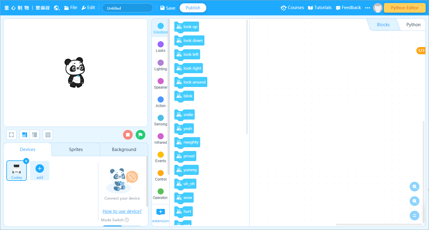
(2) Use a Micro USB cable (Type-C) to connect mBot2 to your PC, and power on mBot2.
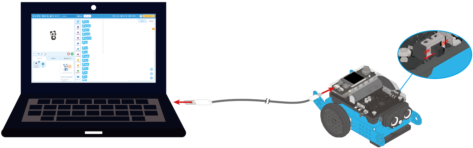
(3) Click "+ add" on the "Devices" tab, select "CyberPi" in the device library, and click "OK".
:::info
Note: mBlock 5 displays the most frequently used device by default, and you can neglect it or delect it before adding a device.
:::
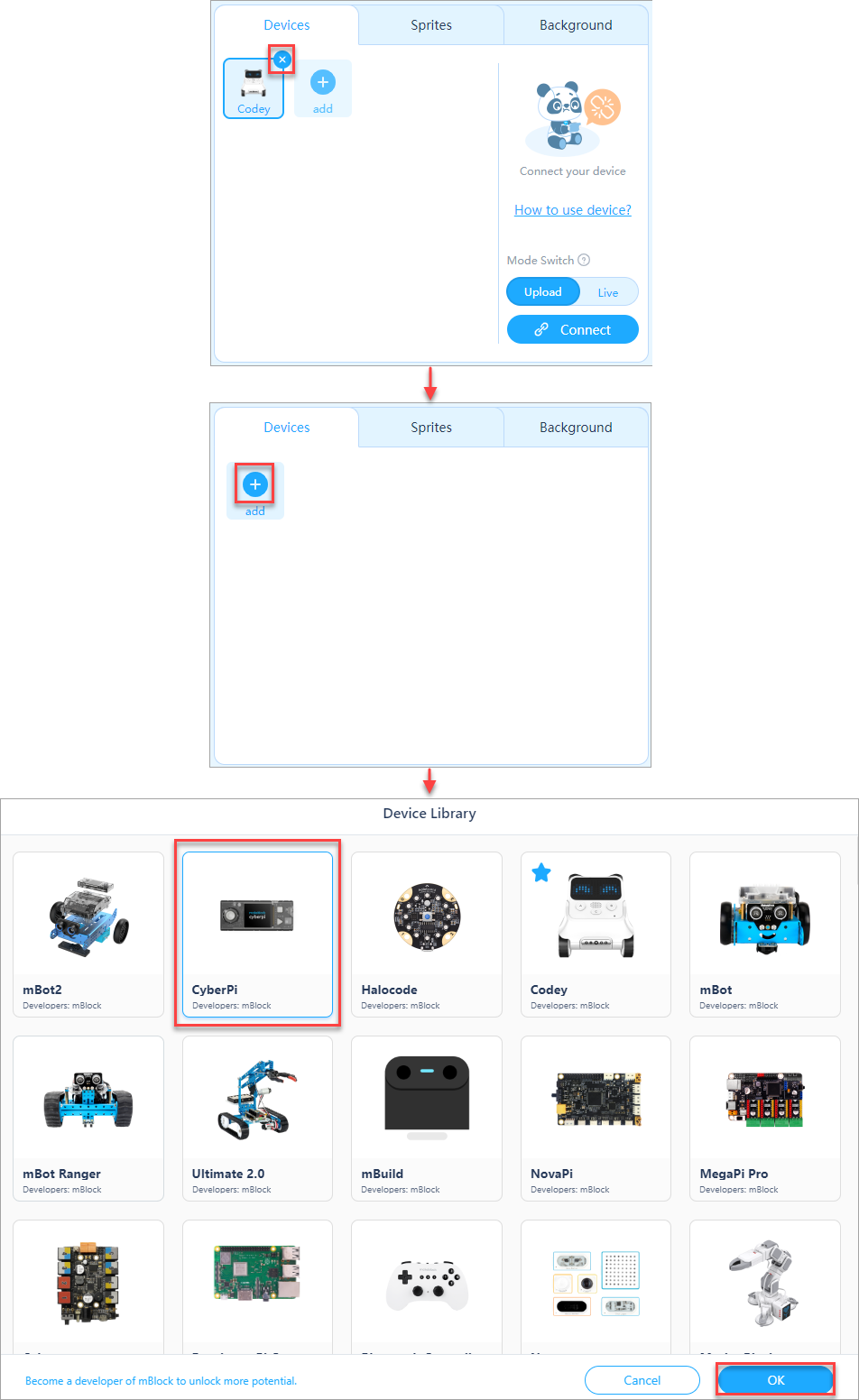
(4) Click "Connect" to connect CyberPi to mBlock 5.
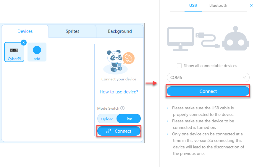
3. Add the extensions required in the obstacle avoidance program
To avoid obstacles, mBot2 uses its ultrasonic sensor 2 to detect obstacles in its way and then respond to them by using the motors and wheels connected to mBot2 Shield. Therefore, you need to add the mBot2 and Ultrasonic Sensor 2 extensions.
(1) Add the "mBot2" extension.
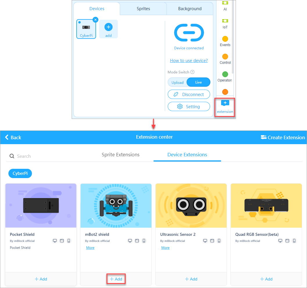
(2) Add the "Ultrasonic Sensor 2" extension.
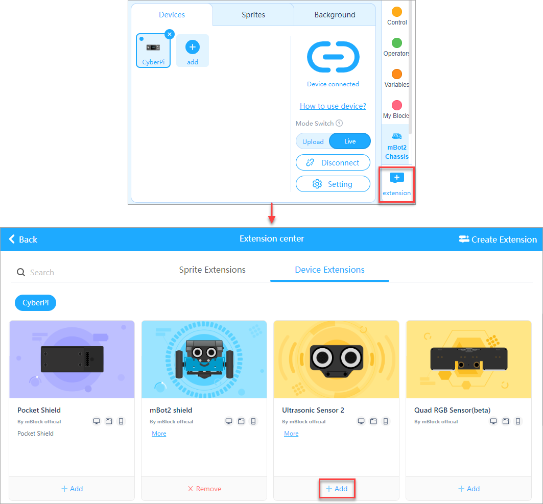 After adding the extensions, you can find the blocks in the blocks area.
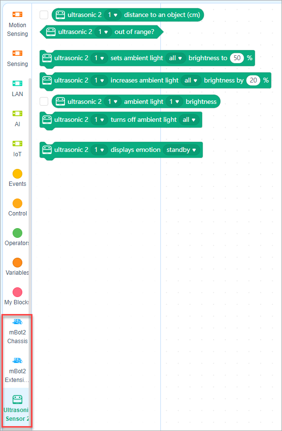
4. Start to write the program
(1) Set the programming mode to "Upload".
Live: In this mode, you can view the program execution effect in real time, which facilitates the debugging of the program. In this mode, you must keep mBot2 connected to mBlock 5. If they are disconnected, the program cannot be executed.
Upload: In this mode, you need to upload the compiled program to mBot2. After being successfully uploaded, the program can still run properly on mBot2 when it is disconnected from mBlock 5.
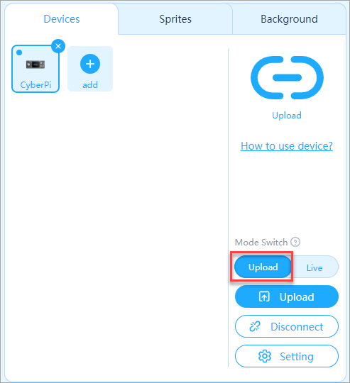
(2) Drag the blocks required to the scripts area.
a. First, define the event for triggering the execution of the obstacle avoidance program. For example, trigger the program by pressing button B.
Click the Events category, drag the block when button () pressed to the scripts area, and click the drop-down list box to select button B.
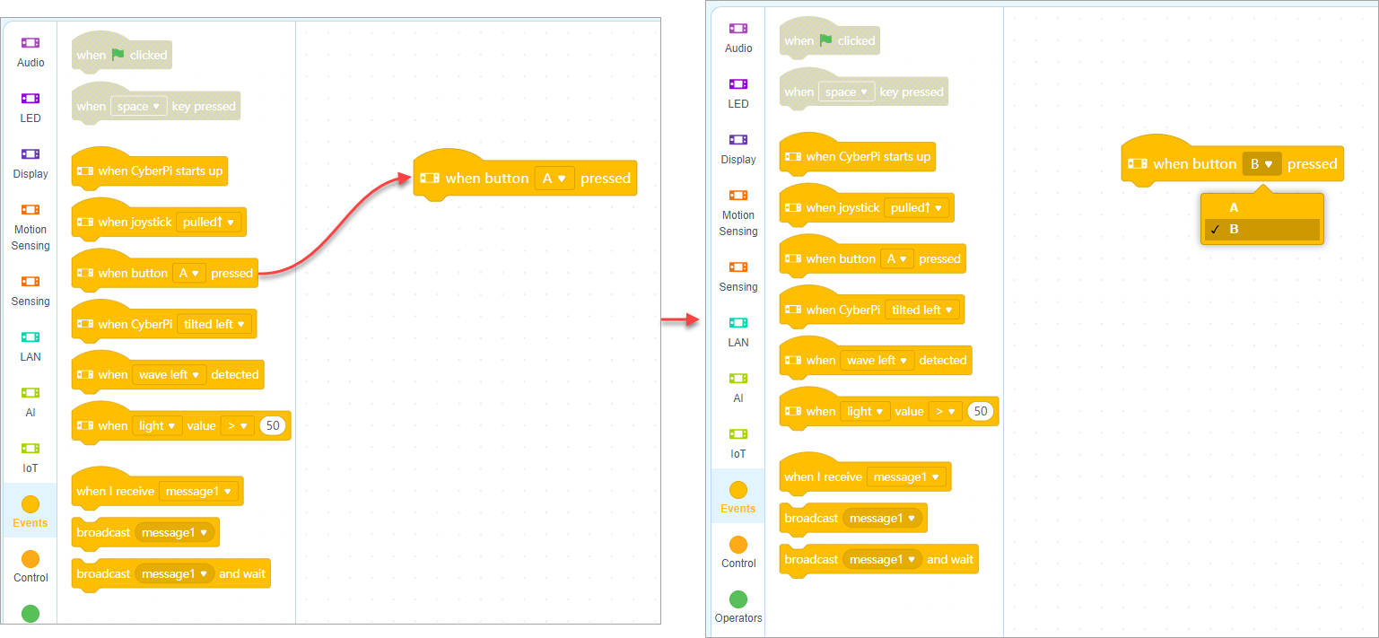
b. Define how many times the program is to be executed. For example, keep executing the program after it is triggered.
Click the Control category and drag the block forever to the scripts area.
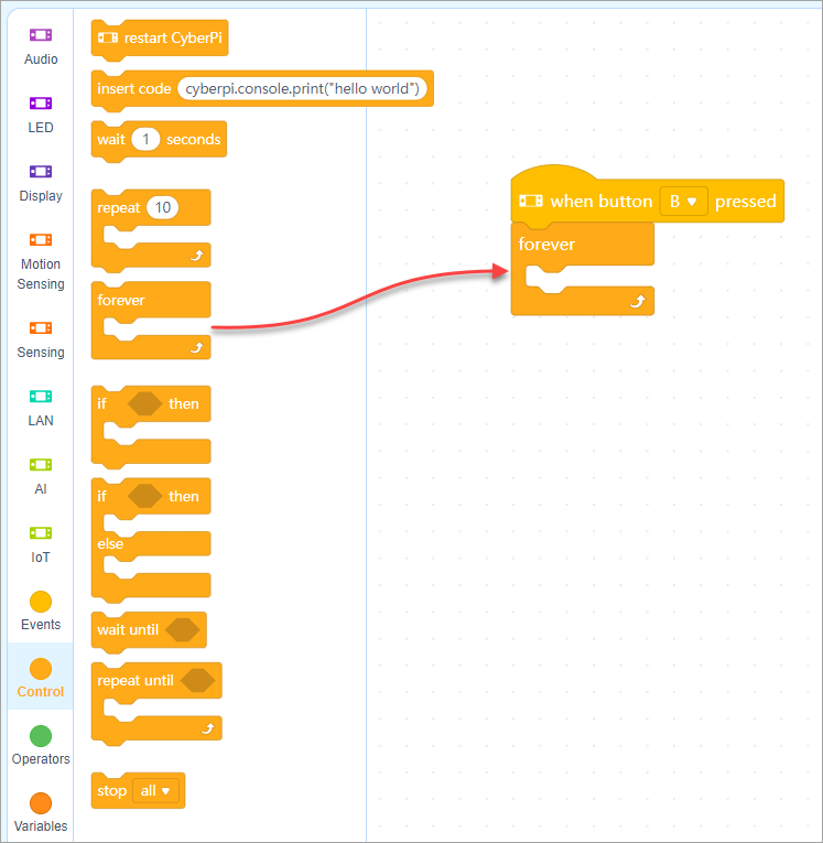
c. Define the specific conditions for avoidance and how mBot2 responds to an obstacle. Define the condition For example, mBot2 starts to avoid an obstacle when it is 9cm or less away from mBot2; and mBot2 keeps moving forward when no obstacle is found or an obstacle is more than 9cm away from it.
Click the Control category and drag the block if () then () else () to the scripts area.
The condition involves the operation of distance.
Click the Operators category and drag the block () > () to the scripts area and put it into the condition block.
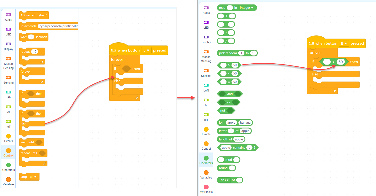 Click the value 50 to change it to 9.
Click the Ultrasonic Sensor 2 category and drag the block ultrasonic 2 () distance to an object (cm) to the scripts area and put it into the operation block.
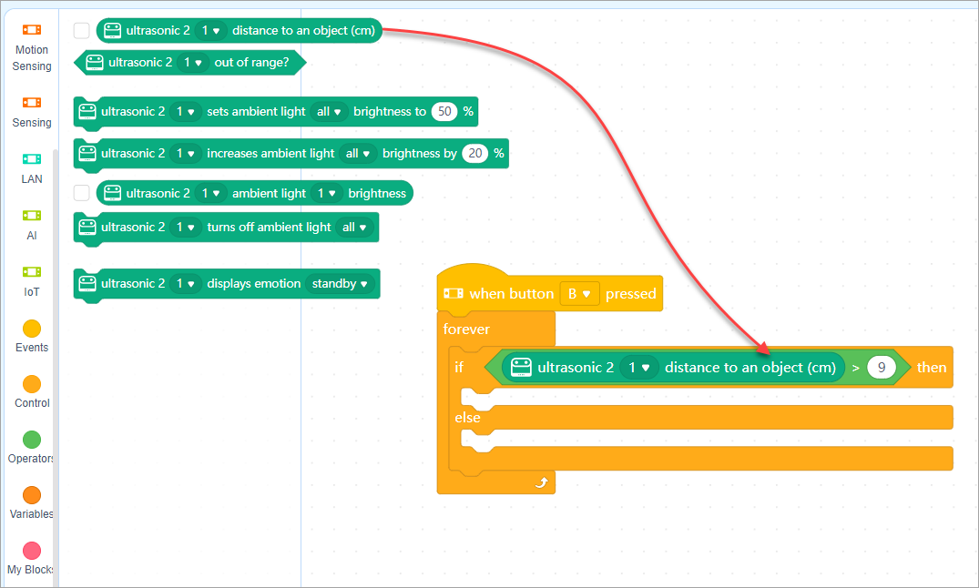
Define the responses
When an obstacle is more than 9cm away from mBot2, mBot2 keeps moving forward.
Click the mBot2 Chassis category and drag the block () at () RPM to the scripts area and put it into the condition block.
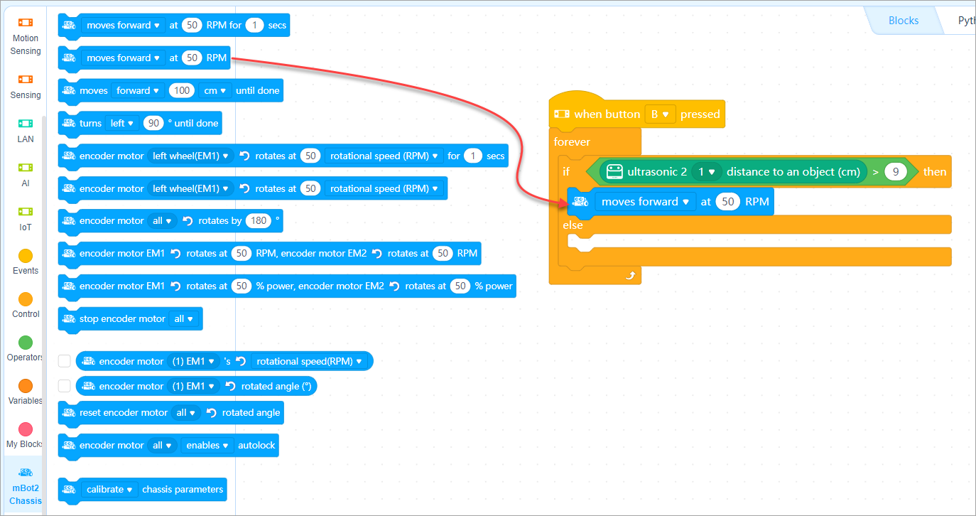 When an obstacle is 9cm or less away from mBot2, mBot2 turns left.
Drag the block () at () RPM for () secs to the scripts area, put it into the condition block, and click the drop-down list box to select turns left.
When an obstacle is 9cm or less away from mBot2, mBot2 turns left.
Drag the block () at () RPM for () secs to the scripts area, put it into the condition block, and click the drop-down list box to select turns left.
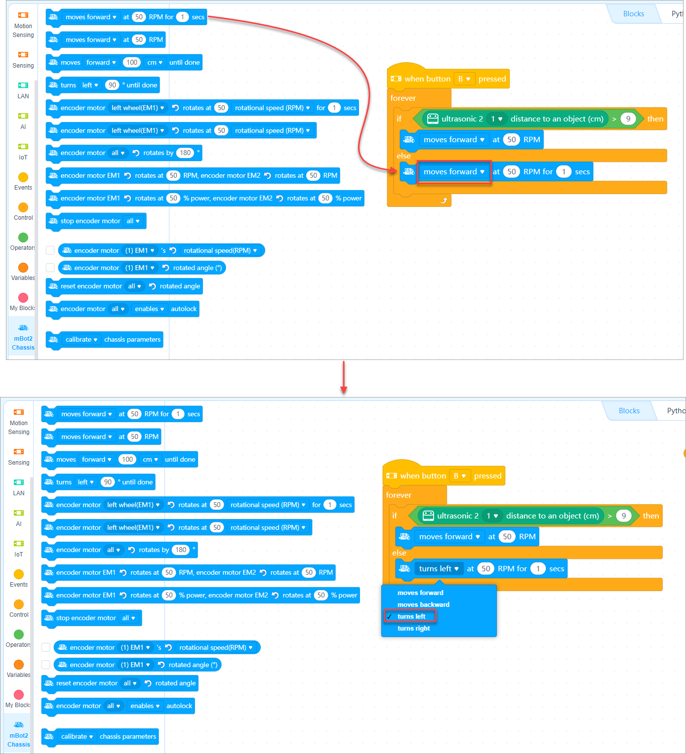 Now, a simple obstacle avoidance program is completed.
5. Upload the program to mBot2
:::info
Note: The program you upload will replace the last program you execute on mBot2.
:::
Click Upload and wait till the uploading is complete.
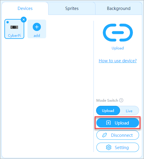 :::info
**About program overriding **
You can find two program categories on CyberPi, namely Preset and My programs. Choose Switch Program and then pull the joystick to the left or right to switch betweem them.
:::info
**About program overriding **
You can find two program categories on CyberPi, namely Preset and My programs. Choose Switch Program and then pull the joystick to the left or right to switch betweem them.
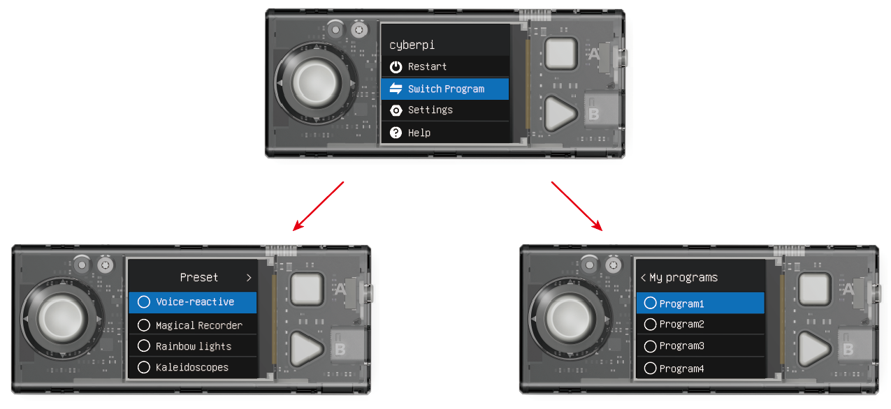 An uploaded program can override a program only in My programs.
-
If you upload a program when you are running a preset program, the program you uploaded override Program1 in My programs. You need to enter My programs to find it and can press button B to run it.
-
If you upload a program when you are running a program in My Programs, the program you upload override the program you are running. For example, you upload a program when you are running Program2, Porgam2 is overridden by the program you upload.
To change the name of a program, see "How to change program names on CyberPi?" :::
6. Execute the program
Press button B on CyberPi.
 mBot2 starts to move forward and detect obstacles. When an obstacle is found and it's 9cm or less away from mBot2, mBot2 turns left for one second and then moves forward.
:::tips Tips:
- You can change the parameter values on the blocks (such as changing the distance threshold or responses) or add more conditions to compile your own obstacle avoidance programs.
- You can also compile other programs (such as a line following program) in a similar way.
- To learn more from example programs, choose Tutorials > Example Programs on the menu bar of mBlock 5. :::
Pocket Shield Operation Guide

1. Know your Pocket Shield
Pocket Shield provides the following functions for CyberPi:
1.1 Supplying power
Pocket Shield is equipped with a rechargeable 800 mAh Li-ion battery that can be charged while supplying power for CyberPi.
The following table describes the charging and power supplying of Pocket Shield.
| Battery life Supplies power for CyberPi with loads, such as servos and motors, in common application scenarios. | More than 4 hours | | --- | --- | | Upper limit of battery life CyberPi operates in the sleep mode with the screen off. | More than 24 hours | | Time to fully charge the battery | About 1 hour |
:::info Note: The charging is slower at the beginning if the battery of Pocket Shield runs too low. The battery life of Pocket Shield may vary according to the operating of CyberPi, the loads it bears, or the use of the battery, as described in the following:
- Pocket Shield is used to drive motors, servos, LED strips, or third-party sensors.
- CyberPi is used to perform high-frequency wireless communication or the LEDs on it are lit up at high brightness for a long time.
- After the lithium-ion battery is charged and discharged for a large number of times, its capacity may decrease. :::
1.2 Extending functions
Pocket Shield provides two types of ports, namely 2-pin and 3-pin ports, which are designed with an anti-plug mechanism and the pin spacing of 2.54 mm. The 2-pin ports can be used to connect motors and the 3-pin ones can be used to connect servos or LEDs strips.
In addition, you can connect third-party sensors to Pocket Shield through DuPont wires.
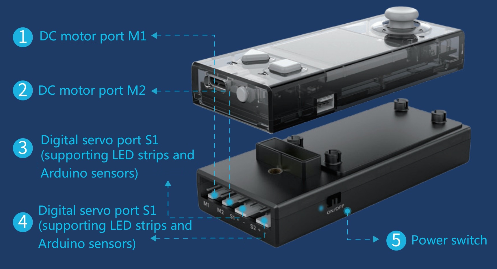
Supported motors
Pocket Shield drives DC motors, water pumps, and fans at a higher voltage (5V) to provide better operation performance, including the torque and rotational speed. This may, however, cause Pocket Shield to fail to drive motors that work well with the earlier products we have developed.
The earlier products we have developed, such as mBot, drive motors at the voltage of 3.7V. The start current of a motor becomes higher when it is driven at a higher voltage, and therefore the start current of such motors may exceed the current limit designed for the protection of the driving chip of Pocket Shield.
To ensure compatibility, refer to the motor driving specifications of Pocket Shield when purchasing motors for it or purchase the motor pack we are going to launch for Pocket Shield.
| Pin spacing | 2.54 mm |
|---|---|
| Output voltage | 5 V |
| Operating current | < 1.2 A |
| Max. transient current | 2.4–4.8 A |
Supported servos
Servos developed by Makeblock are recommended.
Pocket Shield is compatible with third-party servos, but slight angle deviations may occur due to the component protocols.
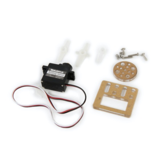
| Pin spacing | 2.54 mm |
|---|---|
| Operating voltage | 5 V |
| Operating current | < 1.6 A |
Supported LED strips
The digital servo ports can also be used to connect LED strips.
LED strips developed by Makeblock are recommended.
Pocket Shield is compatible with third-party LED strips, but control exceptions may occur due to the definition differences of high and low levels in the component protocols.
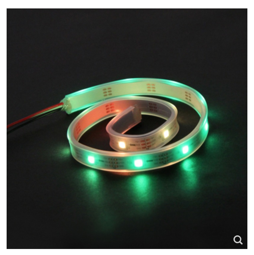
Supported third-party sensors
The output voltage of Pocket Shield is 5 V. It is well compatible with Arduino digital and analog sensors and output modules. The operating voltage of micro:bit sensors is 3.3 V, and therefore Pocket Shield may not work well with them.
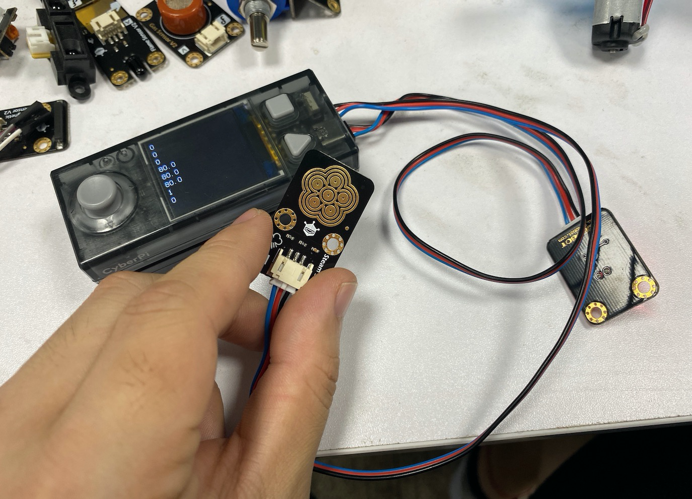 (DF sensor used)
2. Add the Pocket Shield extension
Click + extension and then click + Add in the extension center to add the Pocket Shield extension.
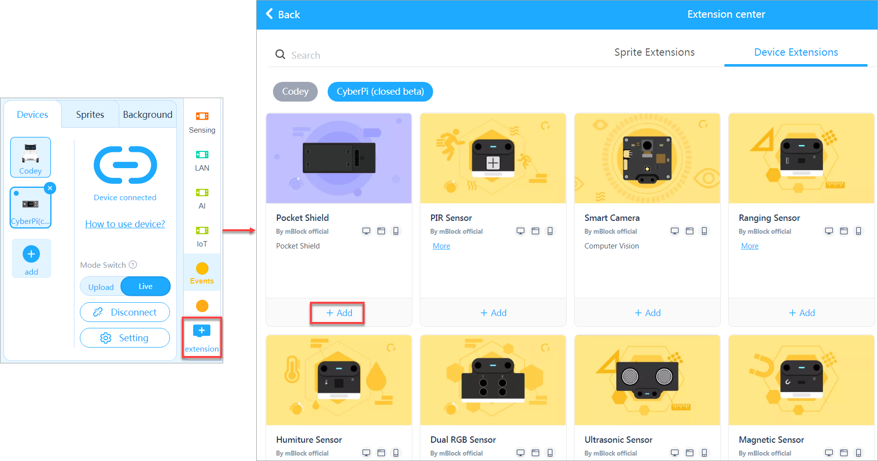 The following blocks are provided in the Pocket Shield extension, indicating the functions that have been developed.
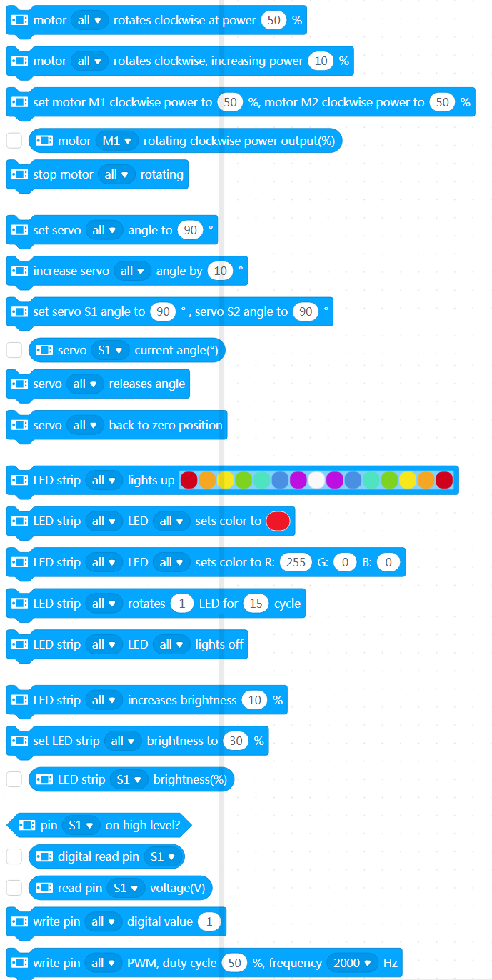 Among them, the following ones are developed for third-party sensors.
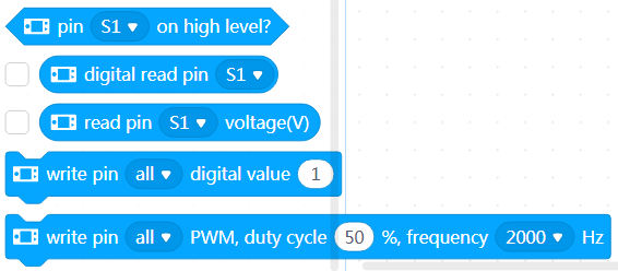
3. Python APIs
For information about the APIs for Pocket Shield, see "APIs for Pocket Shield" in the Python API Documentation for CyberPi.
4. Online help
After-sales services and technical support
If you encounter any product quality problems or find any parts missing or damaged when you open the package, or if you need any technical support, contact us for after-sales services through:** ** support@makeblock.com (Service hours: 9:00–12:00 & 14:00–18:30 from Monday to Friday)
Feedback and suggestions
Should you have any feedback or suggestions on CyberPi, contact our R&D team through: cyber.list@makeblock.com
5. FAQs
How long does it take to fully charge Pocket Shield?
Within two hours. It can be charged faster when powered off.
Can I use CyberPi and Pocket Shield to participate in the Arduino competition?
Working with Pocket Shield, CyberPi supports Arduino modules and parts, but it is a new-generation open-source device designed based on China-made chips instead of Arduino hardware.
CyberPi is designed with high compatibility and can communicate with Arduino main control boards through serial ports or Bluetooth. Therefore, you can use CyberPi as an input or output part for Arduino main control boards to implement powerful and abundant AI and IoT functions in your Arduino projects.
What if the voltage of pins can't be properly obtained?
This is caused by the errors that occur during the switching of pin modes. A new firmware version will be released in August to solve this problem. At present, you can refer to the following program to switch the pins to the correct states to ensure proper voltage output.
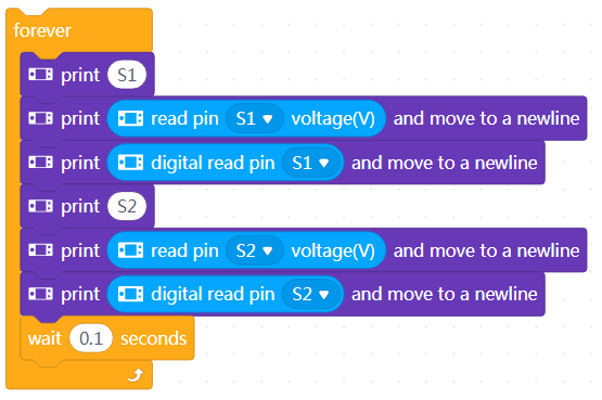
How to update the firmware?
- Connect Pocket Shield to CyberPi through the CyberPi port.
- Use a Type-C USB cable to connect CyberPi to your PC, and turn on Pocket Shield.

- Open the mBlock 5 PC client or webpage, connect CyberPi to mBlock 5, and set the programming mode to Live.
If mBlock 5 prompts you to update the firmware, as shown in the following figure, you need to update the firmware of CyberPi or Pocket Shield.
Click Update. mBlock 5 updates CyberPi or Pocket Shield to the latest firmware version.

6. More information
CyberPi Operation Guide Pocket Shield Operation Guide CyberPi Series User Manual Python API Documentation for CyberPi mBlock 5 Online Help mBlock-Python Editor Online Help
Operation Guide of the "Display +" Extension for CyberPi
Foreword
Hello, I'm Alex Yu, the product manager of CyberPi. I'm glad to introduce the Display + extension to you. It is the key feature update in iteration 003 of CyberPi.
This page describes the details about how to use the Display + extension and provides some example programs, both simple and complicated ones. The content on this page will be continuously updated and improved to help you use the Display + extension more efficiently.
Notice
- The Display + extension is available only for firmware 003 or later of CyberPi. You can update the firmware of CyberPi in OTA mode or on mBlock 5.
- Currently, CyberPi supports only mBlock 5 on the web. The PC client and mobile app will be launched around the end of September.
- The current Display + extension“ is a beta version and provides only some basic functions. Exceptions may occur when you use it, and its design still needs some improvement. Contact us if you have any suggestions or feedback on the improvement of this extension.
- Efforts will be made to ensure the compatibility of later official versions with projects created in the earlier versions, but the compatibility can't be ensured.
- In the short term, this extension will support only the Upload mode and MicroPython programming due to the complexity of object-oriented programming.
Use the "Display +" extension
Add the Display + extension
After connecting CyberPi to mBlock 5, click + extension at the bottom of the blocks area, and then click + Add at the bottom of Display +.
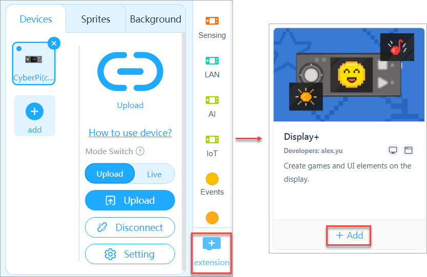
After adding the extension, you can see the Sprites and Doodle blocks.
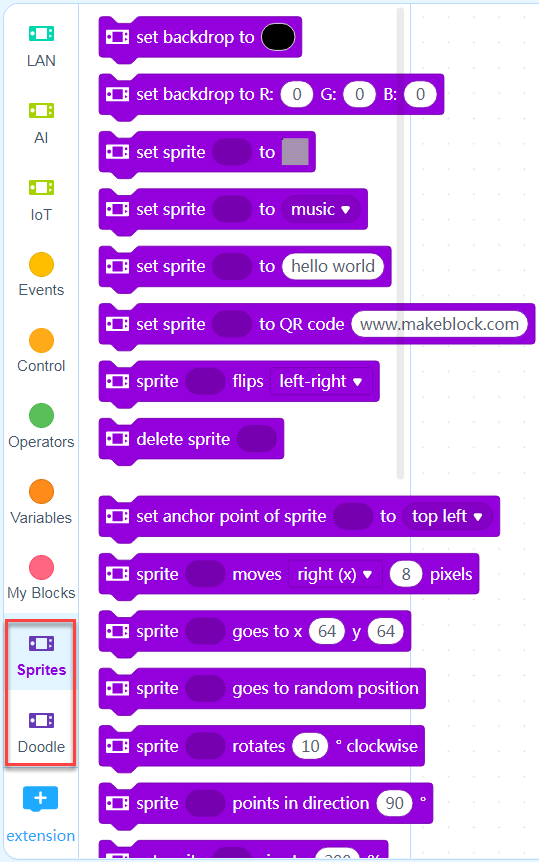
The Display + extension extends the programmable functions of CyberPi's screen. With this extension, you can design apps, games, and more complicated charts on CyberPi.
The Display + extension adopts the concept of object-oriented programming (OOP), and therefore, when you use this extension for programming, you need to define an object first.
The following figure describes the three basic steps for using the Display + extension for programming.
Create a sprite
Create a variable in the Variables category, and then define the variable as a sprite.
:::tips **Tips: **You can name a variable to be defined as a sprite in the format of s__XXX_ to distinguish it from an ordinary one_._ For example, s_text indicates a text variable to be defined as a sprite, and text indicates an ordinary text variable. :::
- Select the Variables category and click Make a Variable.
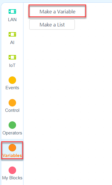
- In the New Variable dialog box that appears, enter the variable name and click OK.
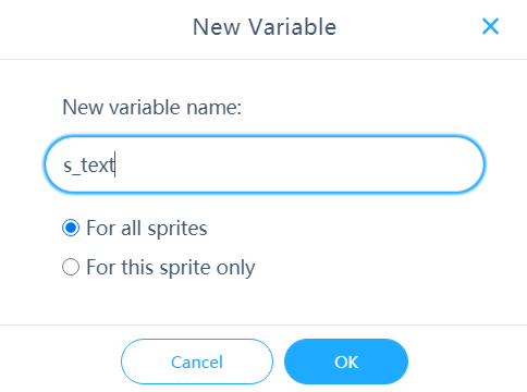 The created variable and its related blocks appear in the Variables category.
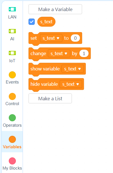
- Set the value of the created variable and define it as a sprite through blocks, as shown in the following example.
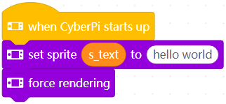
:::tips Summary: The steps for creating a sprite are as follows: creating a variable -> assigning a value and defining it as a sprite -> performing redering to display the sprite
Note that the sprite can be displayed only when you use the force rendering block. :::
If a variable is defined as a sprite, you can no longer perform arithmetic operations on it because data of the sprite type does not support arithmetic operations. Errors may be reported if you do.
For example, an error is reported when you execute the following program.
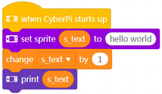
Types of sprites
We have defined multiple types of sprites to facilitate your creation of projects. Generally, you can use the following blocks to define sprites.
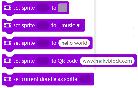
The following table describes the currently available types of sprites.
| Type | Block | Description |
|---|---|---|
| Matrix |  | Defines a matrix image as a sprite |
| Tips: We have restricted the aspect ratio of matrix images for MicroPython programming, allowing you to create larger images, for example, a 128 × 128 (pixel) image. | ||
| Text |  | Defines a text as a sprite |
| Icon |  | Defines a preset icon as a sprite |
| QR code |  | Defines a QR code as a sprite |
| Doodle |  | Defines a sketch as a sprite |
| Tips: The Doodle blocks simulate the structures of Turtles drawing, which work best when you use them to draw geometric figures. |
Modify parameters for sprites
You can modify the parameters for a sprite through blocks or APIs. The following figure shows the currently available parameters for sprites.
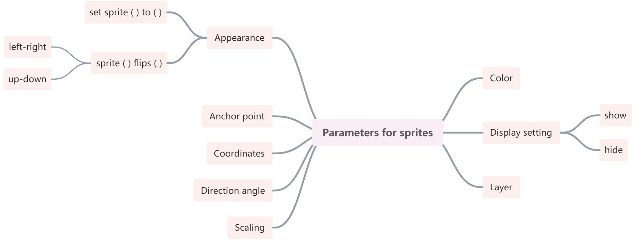 | Parameter | Block | Description |
| --- | --- | --- |
| Appearance |
| Parameter | Block | Description |
| --- | --- | --- |
| Appearance | 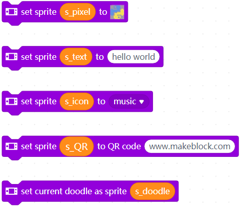 | The appearance of the sprite depends on the blocks set sprite ( ) to ( ) and sprite ( ) flips ( ).
|
| Anchor point |
| The appearance of the sprite depends on the blocks set sprite ( ) to ( ) and sprite ( ) flips ( ).
|
| Anchor point | 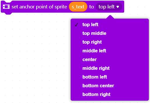 | The anchor point determines the origin of the sprite and its center of rotation. |
| Coordinates |
| The anchor point determines the origin of the sprite and its center of rotation. |
| Coordinates | 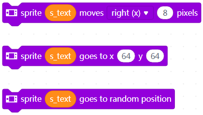 | The coordinates determine the position of the sprite. You can move a sprite by changing its coordinates. |
| Direction angle |
| The coordinates determine the position of the sprite. You can move a sprite by changing its coordinates. |
| Direction angle | 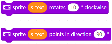 | The direction angle determines the direction the sprite faces. You can rotate a sprite by changing its direction angle. |
| Scaling |
| The direction angle determines the direction the sprite faces. You can rotate a sprite by changing its direction angle. |
| Scaling |  | This block determines the ratio of the to-be-displayed sprite to the original size of the sprite. |
| Color |
| This block determines the ratio of the to-be-displayed sprite to the original size of the sprite. |
| Color | 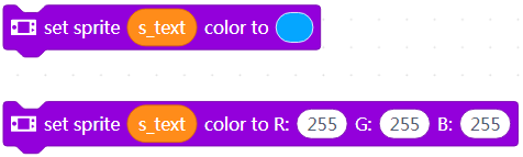 | You can put a color layer over a sprite. For example, you can change the color of a text sprite from white to red. |
| Display setting |
| You can put a color layer over a sprite. For example, you can change the color of a text sprite from white to red. |
| Display setting | 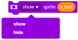 | This block can be used to show or hide a sprite. |
| Layer |
| This block can be used to show or hide a sprite. |
| Layer | 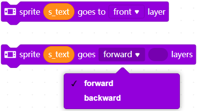 | These blocks can be used to place a sprite on the specified layer. |
:::tips Tips: After a sprite is created, its parameters are set to the default values. When it is changed by using the block set sprite ( ) to ( ), all the other properties remain, except the reflecting effect. The reflecting effect is part of the appearance of the sprite. :::
Rendering
After modifying the properties of a sprite, you need to perform rendering on it to make the new properties take effect, that is, use the block force rendering.
Each time of rendering is similar to generate a frame in animation. Using the force rendering function properly can make better use of the hardware performance.
CyberPi can execute multiple threads simultaneously, and therefore, you can write a thread to implement timed rendering.
The following shows an example.
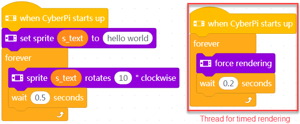 The implementation of the rendering mechanism may be different from other graphical programming logic. We have also tried to design an automatic rendering mechanism but haven't released it due to its stability.
Block help
When you use the Display + extension on mBlock 5, you can right-click a block and click Help that appears to get the help information provided for it.
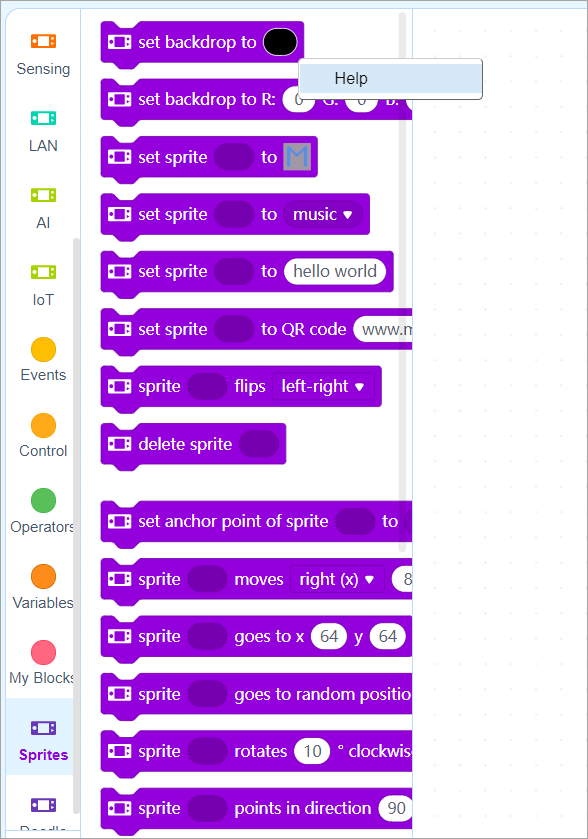
Alternatively, you can open Display+ Block Help to read the help information provided for all the blocks of the Display+ extension. Display+
Others
Detection
Some blocks are designed for users to obtain the status information of sprites. The following describes some of these blocks.
To obtain status information of a sprite, use:
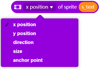 To determine whether a sprite touches another one or the edge of the screen, use:
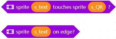 To determine the background color of the screen, use:

Background color setting
To set the color of the background, use:
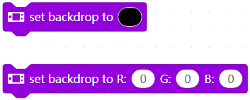 :::info
Note: After setting the color, you need to use the block force rendering to make the setting take effect.
:::
:::info
Note: After setting the color, you need to use the block force rendering to make the setting take effect.
:::
Example programs
Aircraft War
In this example, detection of touching and self-defined matrix images are used. Aircraft War V1.4.rar
Fun with Arithmetic
In this example, the function for defining sprites is used to implement the alternation of questions and answers. Fun with Arithmetic V3.1.rar
FAQson CyberPi
FAQson mBot2
FAQson Troubleshooting
FAQson Product Specifications
HD photos
Vous pouvez les utiliser pour des supports pédagogiques, des brochures, etc. N'oubliez pas de citer la source.
Certification OSHW
La marque de certification OSHW (Open Source Hardware) de CyberPi.
CyberPi
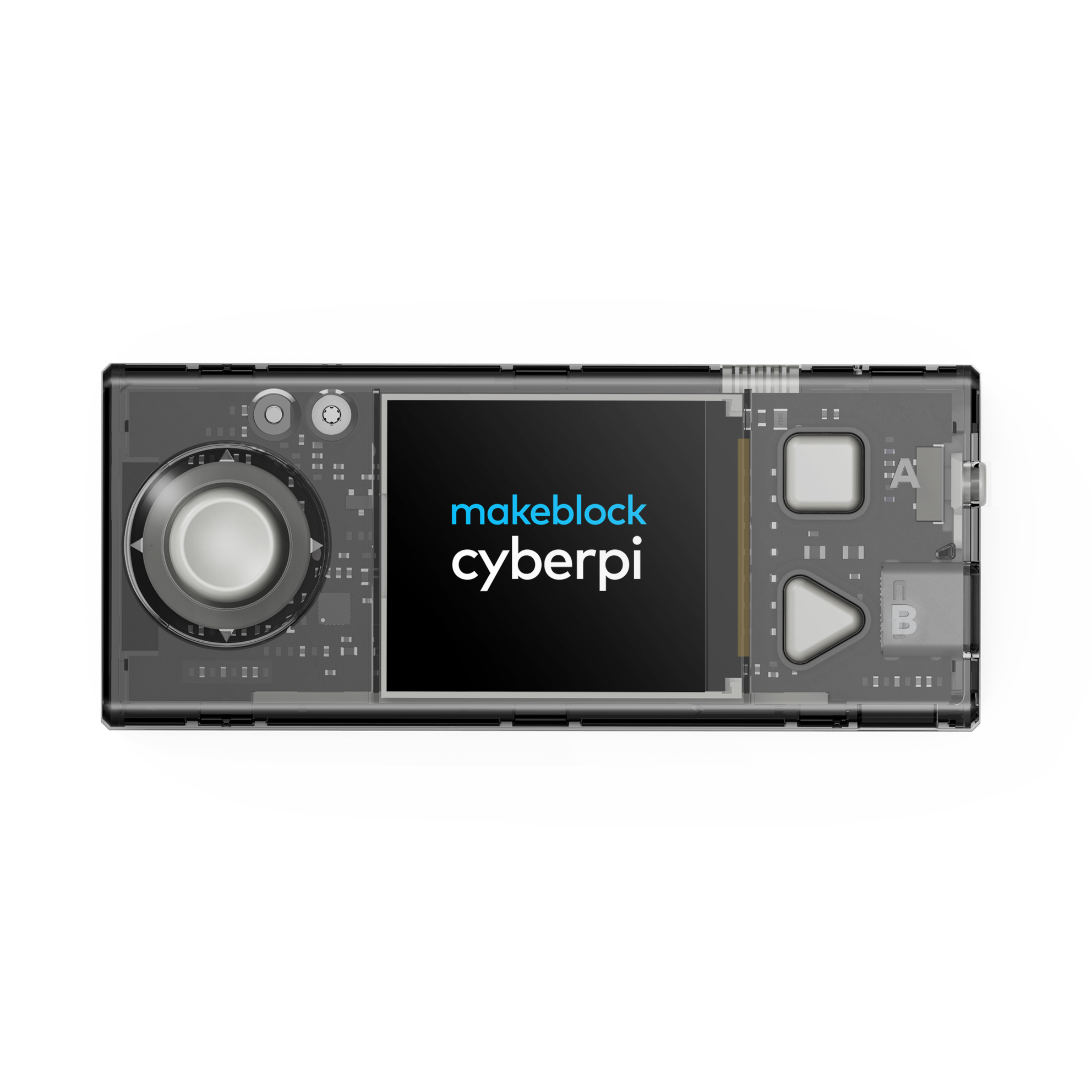
mBot2
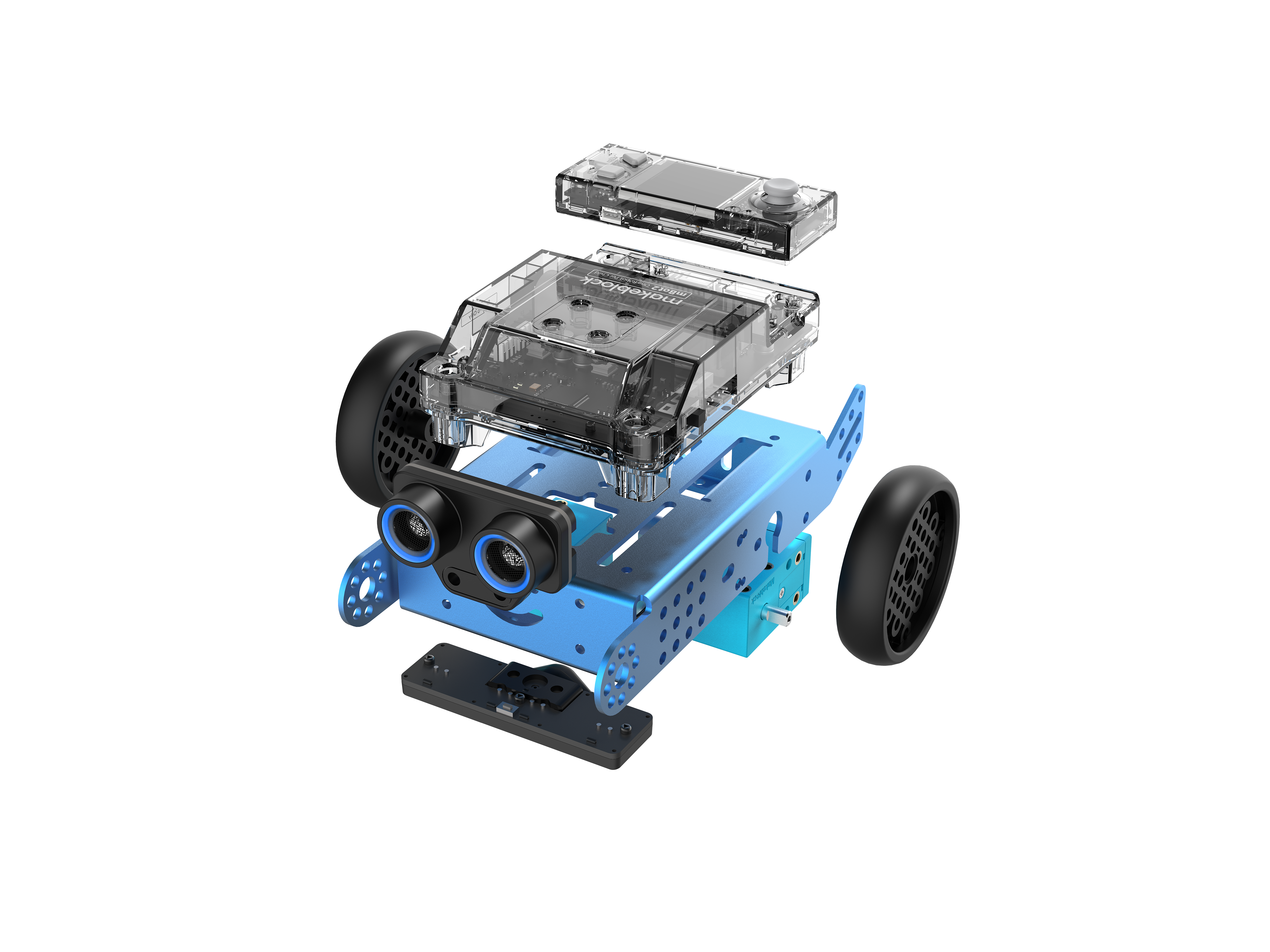
Modules mBuild
Fichier PDF des modules mBuild
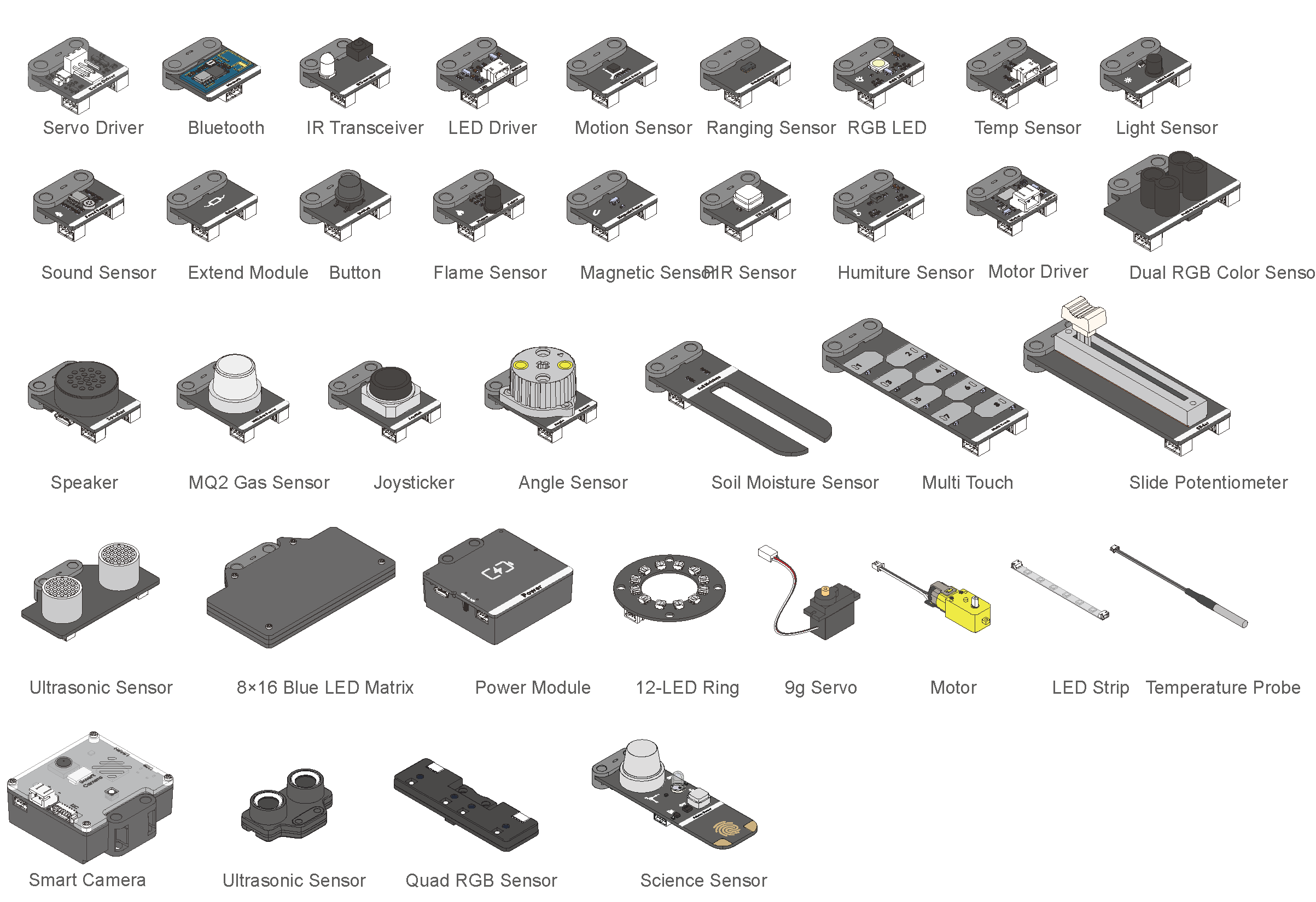
- Source: Photos HD
Program CyberPi with a Third-party Python Editor
Ce qui suit est un guide étape par étape pour les utilisateurs sous Windows. Les utilisateurs de Mac peuvent l'utiliser comme référence.
Démarrage rapide pour les utilisateurs qui ont déjà un environnement Python et un éditeur tiers installés :
- Passez à l'étape 3, ou installez les bibliothèques pyserial et cyberpi avec les commandes suivantes :
pip install pyserialpip install cyberpi
1. Configuration d'un environnement Python
- Allez sur Python.org pour sélectionner et télécharger Python pour votre système d'exploitation.
- Python pour Windows : Téléchargement
- Python pour Mac OS : Téléchargement
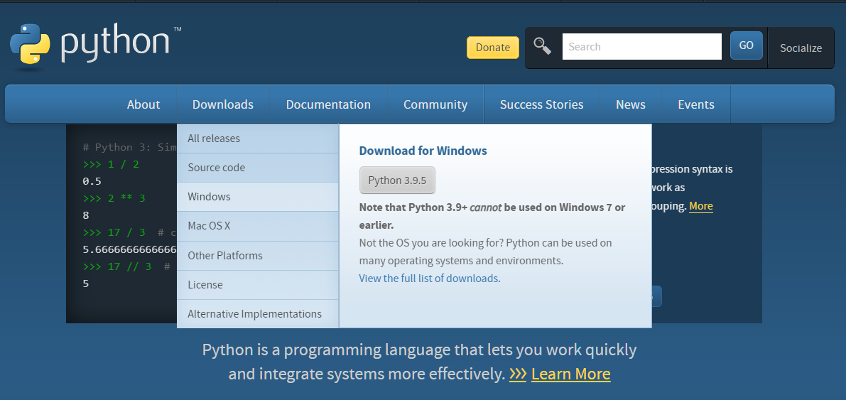
- Cliquez sur la version sélectionnée pour installer, n'oubliez pas de cocher Ajouter Python 3.6 au PATH, puis cliquez sur Installer maintenant.
- Vous pouvez également cliquer sur Personnaliser l'installation pour installer l'environnement Python dans un répertoire spécifié.
2. Installation et configuration de l'éditeur Python tiers (Visual Studio Code à titre d'exemple)
Remarque : Les étapes peuvent varier en fonction de l'éditeur que vous utilisez. Il est également recommandé de configurer l'environnement Python installé dans l'éditeur.
- Téléchargez VS Code selon votre système d'exploitation. Télécharger VS Code
- Cliquez sur le package d'installation téléchargé pour l'installer. (Suivez simplement les invites pour installer)
- Cliquez sur l'icône de VS Code sur le bureau pour exécuter le programme.
- Sur le côté gauche de l'interface du logiciel, trouvez l'icône dans le rectangle rouge comme indiqué ci-dessous et cliquez dessus.
- Recherchez l'extension Python et installez-la. Notez que l'éditeur est Microsoft.
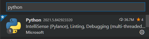
- Configurez l'environnement Python précédemment installé dans l'éditeur VS Code.
- Créez un nouveau dossier et un fichier .py et vous pouvez écrire des programmes Python de base.
3. Préparation pour programmer CyberPi avec l'éditeur tiers
- Sous le système d'exploitation Windows, appuyez sur Windows + R sur le clavier, tapez **CMD **et appuyez sur Entrée, puis la fenêtre CMD s'affichera.
-
Installez la bibliothèque pyserial, qui assure que CyberPi est connecté à l'éditeur tiers via un câble USB ou un dongle Bluetooth.
Tapez `pip install pyserial` dans la fenêtre CMD et appuyez sur **Entrée**, attendez que la bibliothèque soit installée.
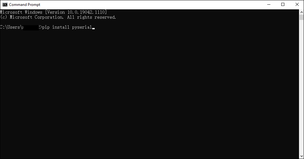
-
Installez la bibliothèque cyberpi, qui est une bibliothèque Python utilisée pour la programmation en ligne de CyberPi.
 Tapez `pip install cyberpi` dans la fenêtre CMD et appuyez sur **Entrée**, attendez que la bibliothèque soit installée.

 Vous pouvez vous référer à la [Documentation de l'API Python pour CyberPi](https://www.yuque.com/makeblock-help-center-en/mcode/cyberpi-api).
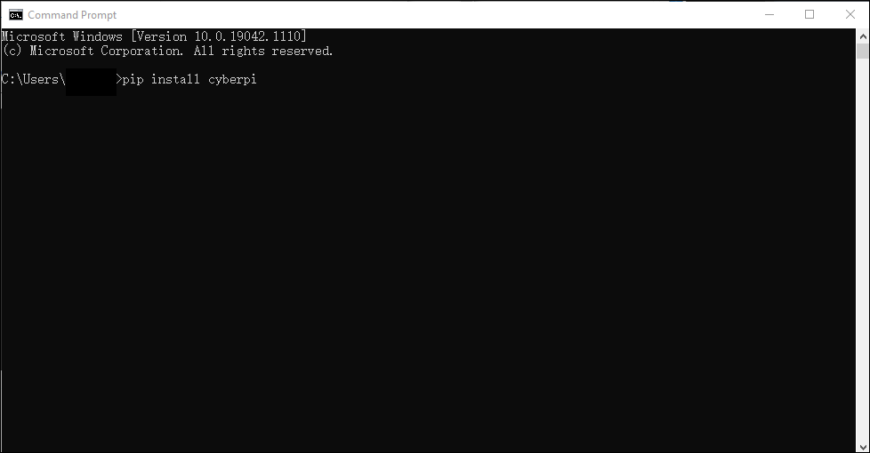
- Après l'installation, vous pouvez écrire des programmes dans l'éditeur configuré avec l'environnement Python.
4. Remarque
L'éditeur tiers prend actuellement uniquement en charge la programmation en ligne pour CyberPi.
5. Exemples de programmes
Souris CyberPi
Nécessite l'installation du module pynput. Référez-vous à l'étape ci-dessus pip install pynput
""""
Nom: Souris Cyber Pi
Introduction:
Utilisez le module gyroscope, les boutons de Cyber Pi, et la fonction de contrôle de la souris du module pynput, pour convertir Cyber Pi en une souris.
Vous pouvez également utiliser le module Bluetooth pour convertir Cyber Pi en une souris sans fil.

""""
from pynput.mouse import Button, Controller
import cyberpi
import time

mouse = Controller()

while True:
    if cyberpi.is_tiltback():
        mouse.move(-3, 0)
        print(mouse.position)
    if cyberpi.is_tiltforward():
        mouse.move(3, 0)
    if cyberpi.is_tiltleft():
        mouse.move(0, -3)
    if cyberpi.is_tiltright():
        mouse.move(0, 3)
    if cyberpi.controller.is_press("b"):
        mouse.press(Button.left)
        mouse.release(Button.left)
        mouse.press(Button.left)
        mouse.release(Button.left)
    if cyberpi.controller.is_press("a"):
        mouse.press(Button.right)
        mouse.release(Button.right)
    time.sleep(0.01)

CyberPi voice typer

""""
Nom: 074 Cyber Pi dactylo vocal
Matériel: Cyber Pi
Introduction:
Utilisez la fonction de reconnaissance vocale de Cyber Pi, et la fonction de contrôle de clavier du module pynput.
Le résultat de la reconnaissance vocale sera imprimé dans un fichier via pynput.
Ce programme prend actuellement uniquement en charge l'anglais.

""""
import cyberpi
from pynput.keyboard import Key, Controller
import time

keyboard = Controller()
cyberpi.console.clear()
cyberpi.led.on(0, 0, 0)
cyberpi.set_recognition_url()
cyberpi.cloud.setkey("Entrez le code d'autorisation du service cloud")    # Vous pouvez l'obtenir via votre compte mBlock
cyberpi.wifi.connect("Nom du WIFI", "Mot de passe du WIFI")
while not cyberpi.wifi.is_connect():
    pass
cyberpi.led.on(0,0,255)
cyberpi.console.println("WIFI connecté")
cyberpi.console.println("--------------")
cyberpi.console.println("Appuyez sur le bouton A pour démarrer la reconnaissance vocale")
while True:
    if cyberpi.controller.is_press('a'):
        keyboard.press(Key.space)
        cyberpi.console.clear()
        cyberpi.led.on(100, 0, 0)
        cyberpi.console.println("Démarrer la reconnaissance vocale")
        cyberpi.audio.play("switch")
        cyberpi.console.println("--------------")
        cyberpi.cloud.listen("anglais", 2)
        cyberpi.led.on(0, 0, 0)
        say = cyberpi.cloud.listen_result()
        cyberpi.console.println(say)
        cyberpi.console.println("--------------")
        for i in say:
            if i == '':
                 keyboard.press(' ')
            else:
                keyboard.press(str(i))
                time.sleep(0.03)

Histogramme de volume Matplotlib

import cyberpi
import time
from matplotlib import pyplot as plt

plt.rcParams['font.sans-serif'] = ['Microsoft YaHei']
plt.ion()

while True:
    loud = cyberpi.get_loudness()
    plt.clf()
    plt.xlabel("Nom des données")
    plt.ylabel("Lectures de volume")
    y_locator = plt.MultipleLocator(5)
    ax=plt.gca()
    ax.yaxis.set_major_locator(y_locator)
    plt.ylim(0,100)
    plt.bar('Volume', loud, align='center',label=f'Température{loud}')
    plt.title('Lectures du capteur de son Cyber Pi')
    plt.legend()
    plt.show()
    plt.pause(0.01)


Matplotlib multi-chart display

import cyberpi
import time
from matplotlib import pyplot as plt

plt.rcParams['font.sans-serif'] = ['Microsoft YaHei']
plt.ion()

while True:
    loud = cyberpi.get_loudness()
    plt.clf()
    plt.xlabel("Nom des données")
    plt.ylabel("Lectures de volume")
    y_locator = plt.MultipleLocator(5)
    ax=plt.gca()
    ax.yaxis.set_major_locator(y_locator)
    plt.ylim(0,100)
    plt.bar('Volume', loud, align='center',label=f'Température{loud}')
    plt.title('Lectures du capteur de son Cyber Pi')
    plt.legend()
    plt.show()
    plt.pause(0.01)
Itération 007
Avant-propos
Cette page fournit des détails sur l'itération 007 de CyberPi.
La plupart des itérations améliorent le produit de manière progressive tout en étant compatibles avec les versions précédentes, de sorte que les programmes que vous compilez pour les versions antérieures peuvent être utilisés dans la dernière version.
La compréhension des informations de cette page peut nécessiter certaines connaissances préalables. Si vous avez déjà acheté la dernière version de CyberPi, ou si vous utilisez une version antérieure et n'avez aucune question sur les mises à jour des fonctionnalités, vous n'avez pas besoin de lire cette page.
Description de la version — Comparée à la version 006
- Ajout de la fonctionnalité sous-jacente de contrôle sur le terrain basé sur le Wi-Fi pour les futures versions officielles de fonctions
- Optimisation des interfaces de démarrage et de menu de CyberOS, facilitant l'utilisation des programmes prédéfinis
- Correction des bugs trouvés et prise en charge de la version améliorée du mBot2 Shield, dans laquelle un port de batterie externe était fourni
- Correction de certains bugs des API Network pour faciliter le développement ultérieur de cours utilisant CyberPi dans des domaines tels que le génie des communications
- Ajout d'API pour mBot2 dans la bibliothèque Python 3 développée pour CyberPi
- Ajout de blocs et de fonctions à la matrice LED 8×16 et au capteur RGB quad | Date de sortie | 30 septembre | | --- | --- | | Version matérielle | CyberPi PCB V1.1 Pocket Shield PCB V1.1 mBot2 Shield PCB V1.1 (PCBA V1.0) mBot2 Shield PCB V1.2 *Un port de batterie externe est ajouté au mBot2 Shield V1.2, afin que le mBot2 puisse être utilisé dans des compétitions avec des exigences de performance plus élevées. | | Version du micrologiciel | Firmware CyberPi 007 (NOUVEAU) Firmware Pocket Shield 006 Firmware mBot2 Shield 004 (NOUVEAU) | | Extension mBlock | Cyberpi 1.1.20 (NOUVEAU) pocket_shield 0.03 mbot2 0.02 mbuild_quad_color_sensor 0.02 cyberpi_mbuild_ultrasonic2 0.01 cyberpi_mbuild_science 0.01 halocode_network 0.0.2 (NOUVEAU) | | IDE mBlock | Version Web 1.0.4 Version PC 5.3.1 Version Mobile 2.1.3 |
Nouvelles fonctionnalités
Contrôle sur le terrain basé sur le Wi-Fi
En mode de contrôle sur le terrain basé sur la bande 433, MakeboX communique avec le module de gestion de l'alimentation sur le robot via la bande 433 et contrôle ainsi le robot et obtient ses informations d'état. En mode de contrôle sur le terrain basé sur le Wi-Fi, MakeboX interagit avec le robot en fonction du protocole Wi-Fi ESP32_NOW. Dans tous les événements de compétition à venir où CyberPi est utilisé, MakeboX contrôlera les robots et obtiendra leurs informations d'état en mode de contrôle sur le terrain basé sur le Wi-Fi.
Interfaces CyberOS
L'interface utilisateur suivante est ajoutée sur CyberOS. Choisissez Paramètres > À propos de CyberPi pour le trouver. Après avoir scanné le code QR avec votre smartphone où l'application officielle MakeX est installée, votre smartphone, MakeboX et CyberPi peuvent communiquer entre eux sans fil.
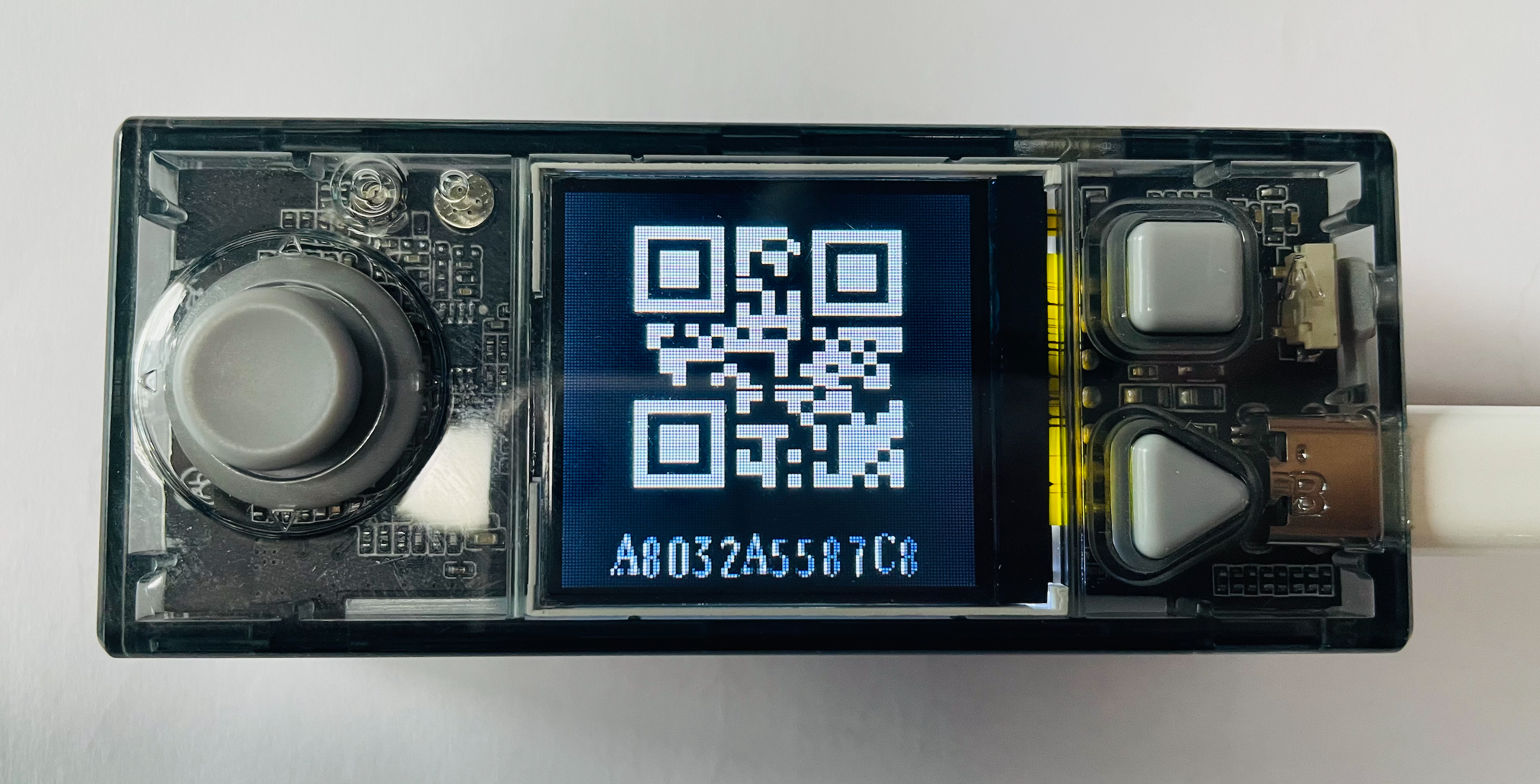 Avec la technologie de contrôle sur le terrain basée sur le Wi-Fi et MakeboX, l'application officielle MakeX peut mettre en pause, redémarrer et surveiller l'état des robots dans les compétitions, ce qui peut être attendu dans certaines compétitions de 2022.
Nouveau bloc et API MicroPython
| Bloc (disponible uniquement en mode de téléchargement) | API |
|---|---|
 | |
| Vous pouvez trouver ce bloc dans la catégorie Détection après avoir ajouté CyberPi depuis la bibliothèque de périphériques. | cyberpi.is_makex_mode(name) |
| Détermine dans quel état se trouve CyberPi. Paramètres: |
namestr, indiquant l'état possible d'une compétition. Plage de valeurs :auto: mode automatiquemanual: mode manuel
Renvoie une valeur booléenne. Remarque : Une compétition peut être dans un autre état que ces deux états, selon les états par défaut que vous avez définis sur CyberPi avant de le connecter à MakeboX. |
Version officielle de l'extension Contrôleur Bluetooth pour CyberPi
Le firmware 007 prend en charge officiellement l'extension Contrôleur Bluetooth, et vous pouvez utiliser les blocs suivants pour écrire vos programmes.
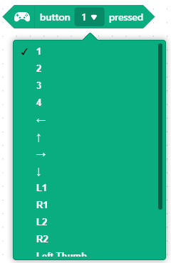

Fonction de calibration de châssis
Fonction de calibration de châssis dans laquelle CyberPi suit un mouvement à une distance spécifique sur la surface de la table, puis corrige automatiquement les erreurs causées par l'inclinaison, garantissant ainsi le mouvement précis des robots.
Expressions de matrice LED 8×16
Ajout d'expressions de matrice LED 8×16 avec des opérations conditionnelles if...else, afin que vous puissiez exprimer plus de formes et de dessins avec des matrices LED. Pour plus de détails, reportez-vous à la documentation de la matrice LED 8×16.
Corrections de bugs et améliorations de l'expérience utilisateur
- Ajout de la programmation Python 3 pour mBot2. Pour plus de détails, reportez-vous à la documentation Python 3.
- Modification de la fonction Wi-Fi pour une meilleure communication ESP32_NOW.
- Modification de la fonction de charge rapide pour mBot2.
- Optimisation de CyberOS avec une interface de démarrage mise à jour et une hiérarchie de menus.
- Amélioration des performances de mouvement de mBot2.
- Amélioration de l'extension du capteur RGB quad.
Pour plus d'informations sur ces mises à jour, veuillez vous référer au document original.
Itération 006
Avant-propos
Cette page décrit les détails concernant l'itération 006 de CyberPi. Le résultat de chaque itération est une version majeure de CyberPi.
La plupart des itérations améliorent le produit de manière progressive tout en étant compatibles avec les versions antérieures, de sorte que vos programmes compilés pour les versions précédentes peuvent être utilisés dans la dernière version.
La compréhension des informations fournies sur cette page peut nécessiter certaines informations de base. Si vous avez acheté la dernière version de CyberPi ou utilisez une version antérieure sans questions sur les mises à jour des fonctions, vous n'avez pas besoin de lire cette page.
Description de la version
Comparée à la version 005, la version 006 fournit de nouvelles fonctions et caractéristiques et résout les bugs trouvés. Dans cette version, les API liées à notre nouveau capteur Science Sensor sont prises en charge, et les API et fonctions de l'extension Display+ sont testées et améliorées.
| Date de lancement | 31 mars 2021 |
|---|---|
| Version matérielle | CyberPi PCB V1.1 |
| Pocket Shield PCB V1.1 | |
| mBot2 Shield PCB V1.1 (PCBA V1.0) | |
| Version du micrologiciel | CyberPi 006 (NOUVEAU) |
| Pocket Shield 006 | |
| mBot2 Shield | |
| Version du plugin de bloc | cyberpi 1.0.12 (NOUVEAU) |
| pocket_shield 0.03 | |
| mbot2 0.02 (NOUVEAU) | |
| mbuild_quad_color_sensor 0.02 (NOUVEAU) | |
| cyberpi_mbuild_ultrasonic2 0.01 (NOUVEAU) | |
| cyberpi_mbuild_science 0.01 (NOUVEAU) | |
| Version mBlock 5 | Version Web 1.0.4 |
| Version client PC 5.3.1 | |
| Version de l'application mobile 2.1.3 |
Mise à jour du micrologiciel
Méthode 1 : Ouvrez mBlock 5 et mettez à jour le micrologiciel de CyberPi comme indiqué. Si mBlock 5 ne vous invite pas à mettre à jour le micrologiciel, votre CyberPi fonctionne avec la dernière version du micrologiciel. Méthode 2 : Connectez votre CyberPi à Internet via Wi-Fi, accédez à CyberOS et choisissez Paramètres > Mise à jour. Le système vérifie la version actuelle et met à jour le micrologiciel s'il n'est pas à jour.
La méthode 2 est recommandée. Elle prend moins de temps pour effectuer la mise à jour du micrologiciel.
Nouvelles fonctionnalités
Rapport d'erreur
Lorsqu'une erreur se produit pendant l'exécution du programme, CyberPi rapporte l'erreur sur son écran.
Nom de programme défini par l'utilisateur
Après avoir téléchargé un programme sur CyberPi, le nom que vous avez défini pour le programme s'affiche dans la liste des programmes lorsque vous basculez entre les programmes sur CyberOS.
Par exemple, j'écris un programme, je le nomme makeblock, et je le télécharge sur CyberPi. Ensuite, je peux voir le programme makeblock lorsque je bascule entre les programmes.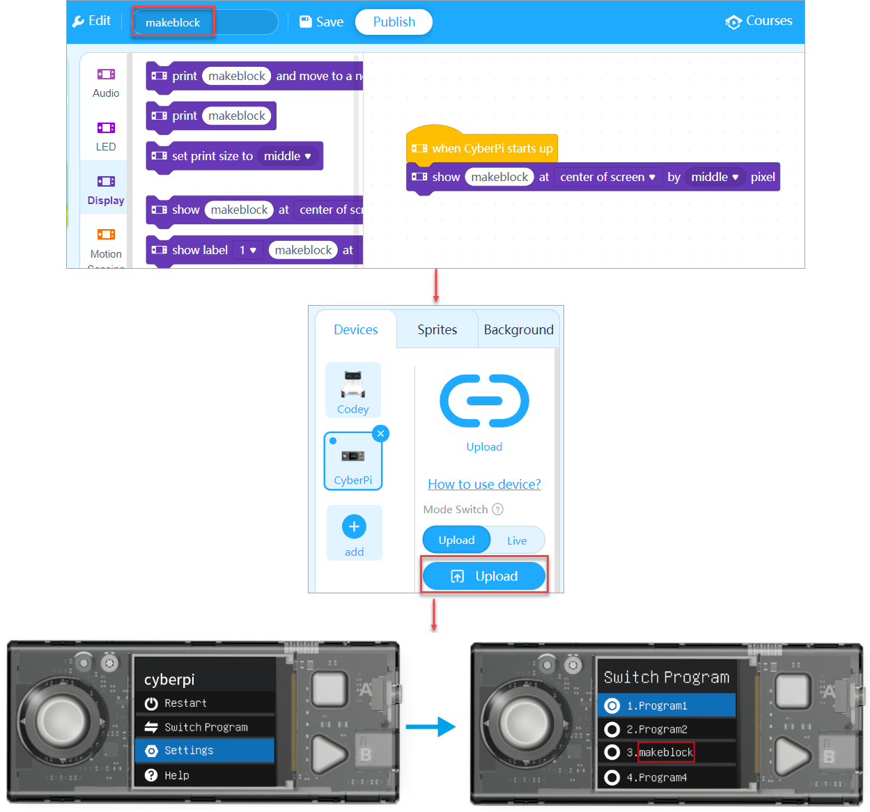 :::info
**Note : **Le programme téléchargé est le troisième programme car le dernier programme que j'ai exécuté avant de télécharger ce programme était le troisième.
:::
:::info
**Note : **Le programme téléchargé est le troisième programme car le dernier programme que j'ai exécuté avant de télécharger ce programme était le troisième.
:::
Applications mobiles mBlock 5 (pour iOS et Android)
Les applications mobiles de mBlock 5 prennent en charge CyberPi et ses extensions. Vous pouvez télécharger les applications sur les boutiques d'applications. Assurez-vous que la version de l'application est la version 2.1.3 ou ultérieure.
Utilisez votre téléphone ou votre tablette pour scanner le code QR et télécharger l'application.

 Alternativement, recherchez "Makeblock" dans les boutiques d'applications pour télécharger l'application.
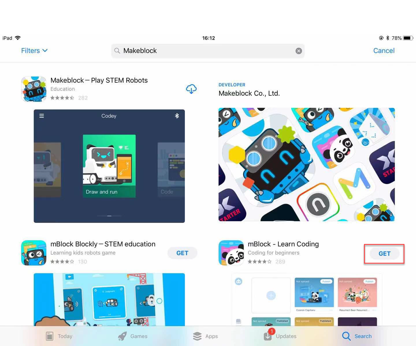
Capteur de science
Le capteur de science est un nouveau module mBuild. Vous pouvez ajouter l'extension Science Sensor sur mBlock 5 pour programmer le capteur de science.
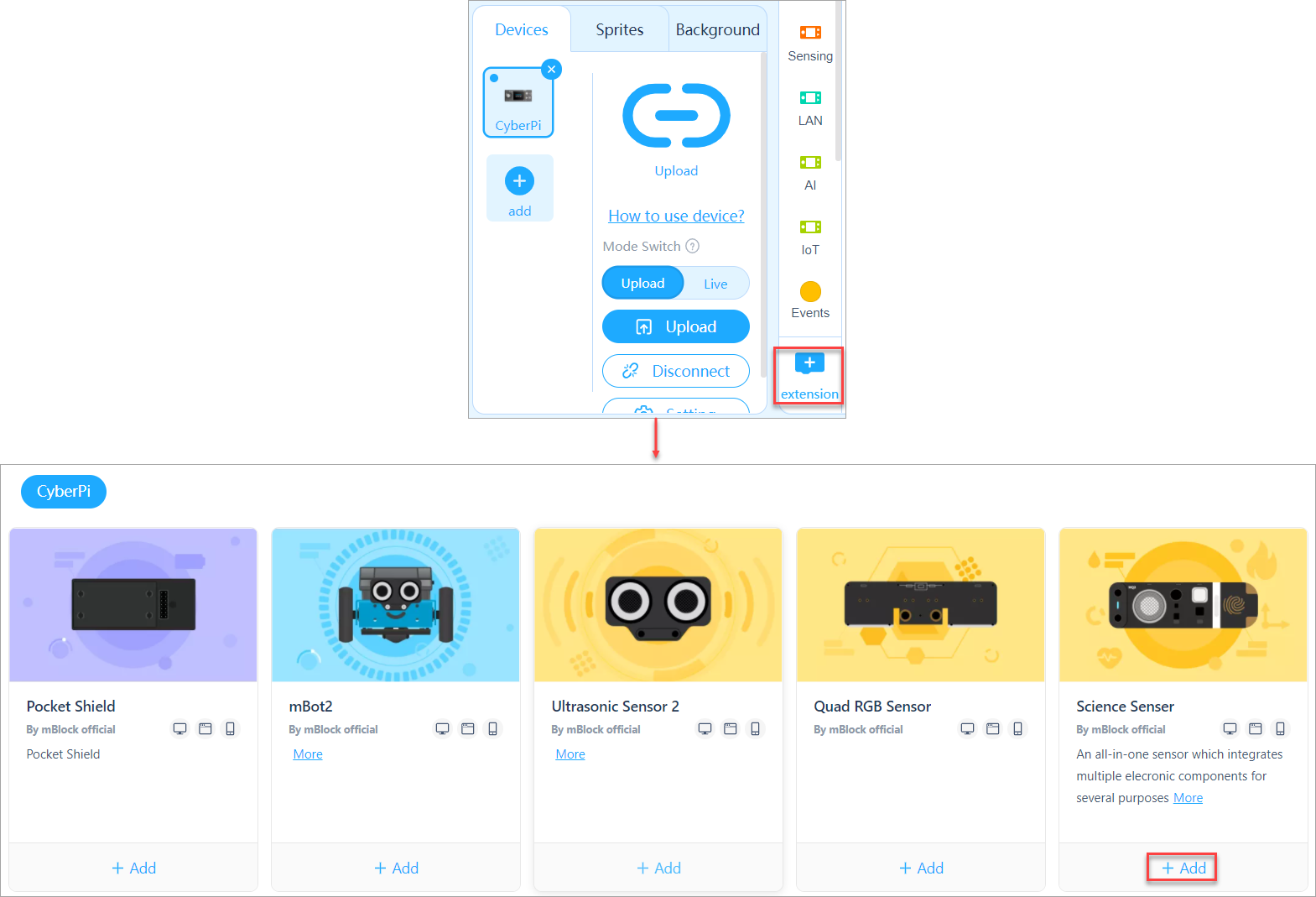
Publication officielle de l'extension Display+
L'extension Display+ et ses fonctions associées sont testées, améliorées et stabilisées.

Contrôleur Bluetooth
CyberPi prend en charge le contrôleur Bluetooth. Après avoir connecté le contrôleur Bluetooth à CyberPi via Bluetooth, vous pouvez ajouter l'extension du contrôleur Bluetooth sur mBlock 5 pour le programmer afin de contrôler CyberPi ou mBot2.
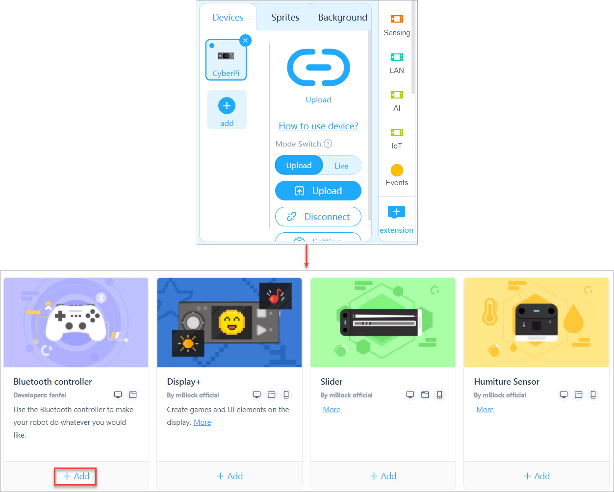
Émotions prédéfinies fournies pour le capteur Ultrasonic 2
Plusieurs émotions prédéfinies sont fournies pour le capteur Ultrasonic 2, facilitant l'expression de vos émotions.
Après avoir ajouté l'extension Ultrasonic Sensor 2, vous pouvez utiliser le bloc d'émotion.
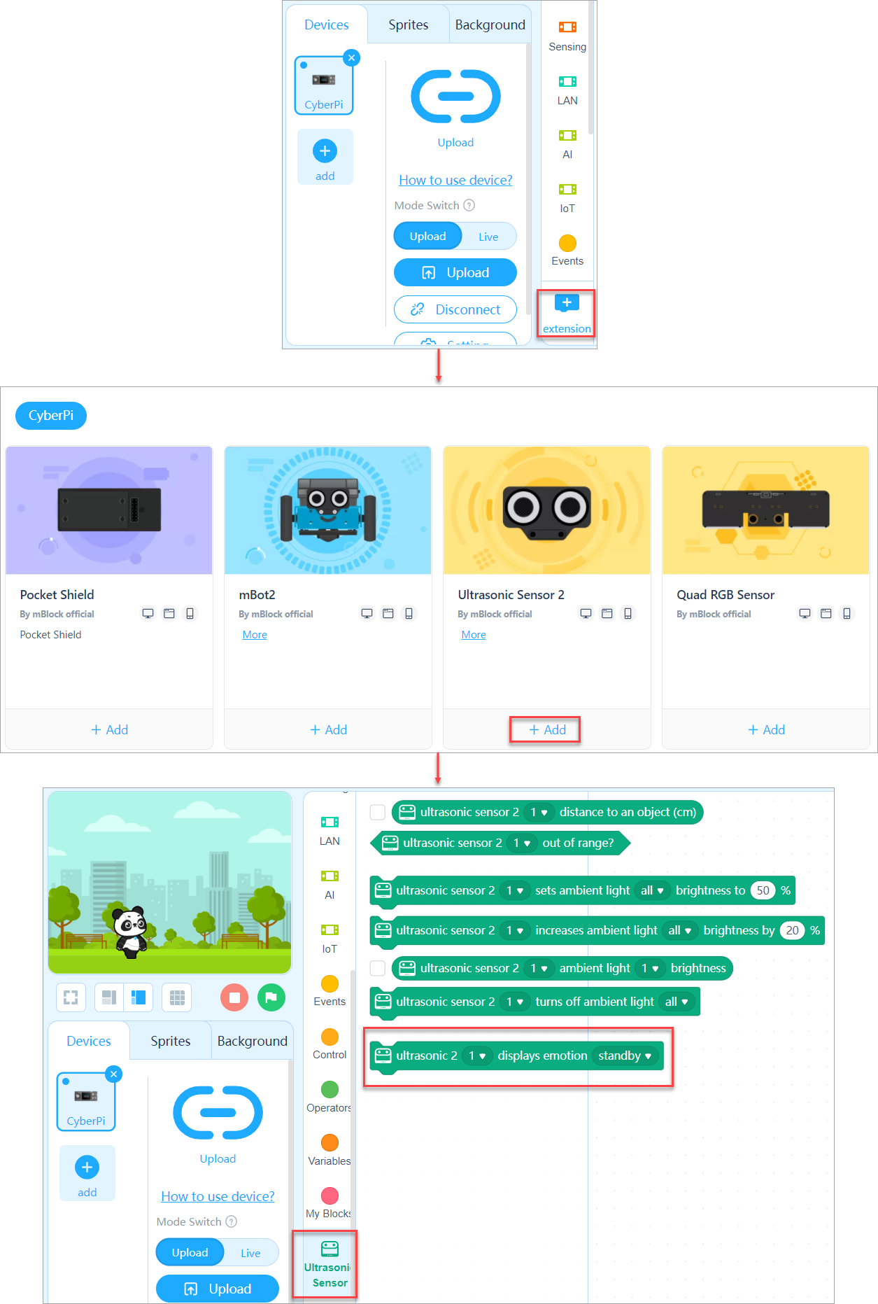
Chargement rapide pour le module mBot2
La fonction de chargement rapide est disponible uniquement pour le module mBot2.
Sur CyberOS, choisissez Paramètres > Chargement rapide pour démarrer le chargement du module mBot2. La tension et le courant de charge sont de 5 V et 2 A.
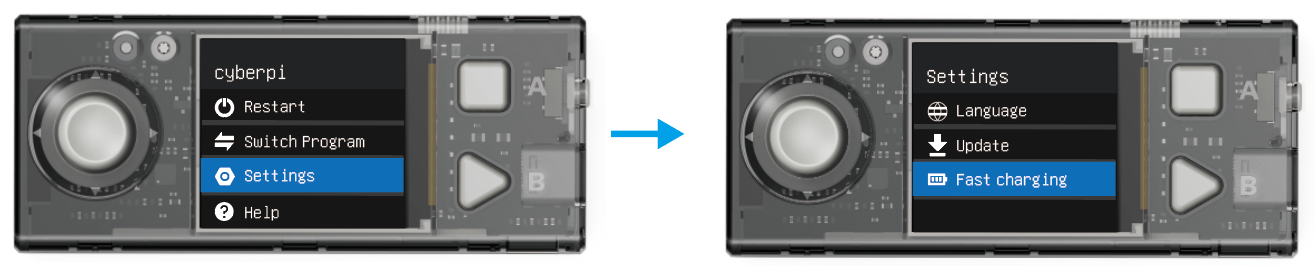 :::info
Note : Les cartes d'extension peuvent être chargées via CyberPi uniquement à la tension de 5 V. N'utilisez pas d'adaptateur secteur dont la tension de sortie dépasse 5 V pour les charger.
:::
:::info
Note : Les cartes d'extension peuvent être chargées via CyberPi uniquement à la tension de 5 V. N'utilisez pas d'adaptateur secteur dont la tension de sortie dépasse 5 V pour les charger.
:::
Nouvelles fonctionnalités pour les tests fermés
Google Sheets (hors de la Chine continentale)
CyberPi peut utiliser des feuilles Google publiques via l'extension Google Sheets. Avec cette fonction, vous pouvez télécharger les données produites par les capteurs et collecter des statistiques sur les données dans les feuilles.
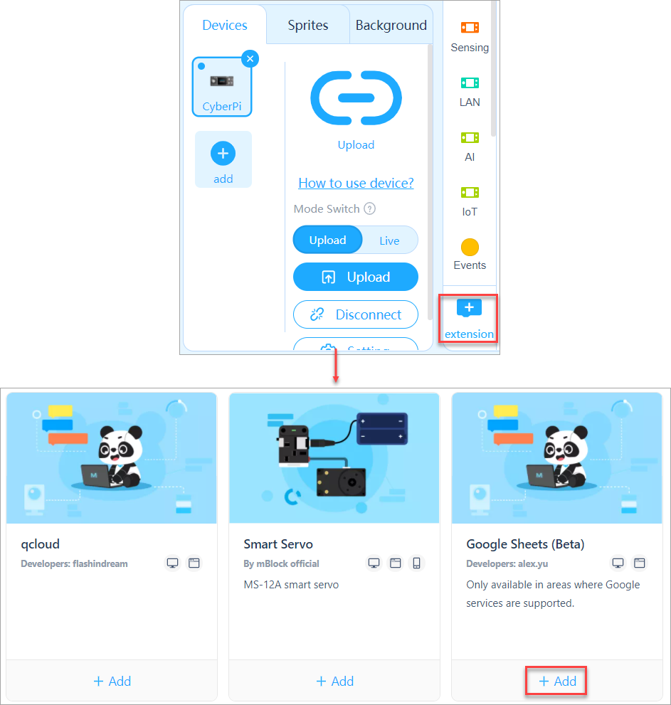
Autorisations pour contrôler le Wi-Fi, le Bluetooth et les broches
Des API pour contrôler le Wi-Fi, le Bluetooth et les broches sont fournies au niveau de l'API micro-python.
Amélioration de l'expérience utilisateur
Sur mBlock 5, choisissez Tutoriels > Programmes d'exemple et cliquez sur mBot2 pour afficher les programmes d'exemple fournis pour mBot 2.
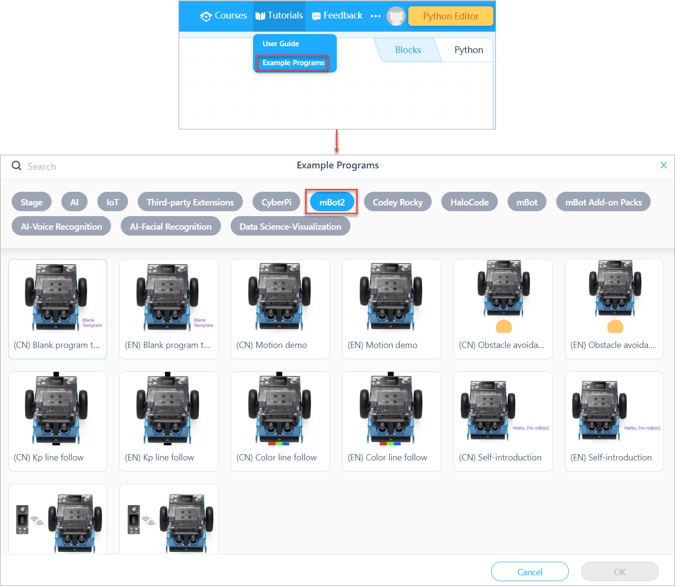
Itération 003
Avant-propos
Cette page décrit les détails de l'itération 003 de CyberPi. Le résultat de chaque itération est une version majeure de CyberPi.
La plupart des itérations amélioreront le produit de manière incrémentielle tout en étant compatibles avec les versions antérieures. Par conséquent, vos programmes compilés pour les versions antérieures peuvent être utilisés dans la dernière version.
Comprendre les informations fournies sur cette page peut nécessiter certaines connaissances préalables. Si vous avez acheté la dernière version de CyberPi ou utilisez une version antérieure sans questions sur les mises à jour de fonctionnalités, vous n'avez pas besoin de lire cette page.
Description de la version
Le résultat de l'itération 003 est la première version majeure de CyberPi. Le tableau suivant décrit les versions de son matériel, micrologiciel et plugin de bloc.
| Date de lancement | 20 août 2020 |
|---|---|
| Version du matériel | CyberPi PCB V1.1 |
| Pocket Shield PCB V1.1 | |
| Version du micrologiciel | CyberPi 003 (NOUVEAU) |
| Pocket Shield 006 (NOUVEAU) | |
| Version du plugin de bloc | cyberpi 1.0.9 (NOUVEAU) |
| sprite 0.01 (NOUVEAU) | |
| pocket 0.03 (NOUVEAU) |
Mise à jour du micrologiciel
Ouvrez mBlock 5 et mettez à jour le micrologiciel de CyberPi comme indiqué. Si mBlock 5 ne vous invite pas à mettre à jour le micrologiciel, votre CyberPi fonctionne avec le dernier micrologiciel. Alternativement, connectez votre CyberPi à Internet via Wi-Fi, entrez dans CyberOS et choisissez Paramètres > Mise à jour. Le système vérifie la version actuelle et met à jour le micrologiciel s'il n'est pas à la dernière version.
Résumé de l'itération
1. Rectification et amélioration
Rectification des problèmes trouvés dans la version du micrologiciel 002 pour stabiliser les blocs et les fonctions de CyberPi, et apporter certaines améliorations, comme décrit ci-dessous :
- Suppression du couplage étroit entre la couleur du pinceau et les paramètres de texte. Dans la version précédente, l'impression des textes changeait immédiatement avec le changement de la couleur du pinceau ; dans cette version, après avoir réglé la couleur du pinceau, elle est appliquée à un texte uniquement après avoir programmé pour imprimer à nouveau le texte.
- Modification de la lecture des sons en mode En direct pour qu'elle soit cohérente avec celle en mode Téléversement, permettant à la lecture en mode En direct d'être interrompue par un autre thread.
- Ajustement fin du mécanisme de battements pour les blocs de lecture de piano, rendant la logique d'implémentation cohérente avec celle de l'extension Music pour les sprites sur mBlock 5.
- Optimisation du mécanisme de lecture du buzzer, éliminant l'interruption de lecture causée par le changement de fréquence.
- Rectification des erreurs survenues lorsqu'un diagramme à barres était pivoté à l'écran.
- Rectification des problèmes selon lesquels les diagrammes à barres et les diagrammes linéaires ne prenaient en charge que les entiers.
- Amélioration de l'affichage des diagrammes linéaires, en arrêtant le démarrage à partir du point zéro.
- Amélioration du format des tableaux, remplaçant le style de couleur graduée par le style noir et blanc.
- Modification de la logique d'exécution des en-têtes d'événement en mode En direct pour être cohérente avec celle en mode Téléversement sur mBlock 5, c'est-à-dire qu'un en-tête d'événement correspond à un seul thread au lieu de plusieurs lorsqu'il est déclenché plusieurs fois.
- Mise à jour des programmes par défaut fournis sur CyberPi. Les programmes d'origine incluaient certains éléments politiquement sensibles et pourraient poser des problèmes de droits d'auteur. Dans cette version, les blocs et le code Python de tous les programmes par défaut peuvent être fournis aux utilisateurs.
- Rectification du problème selon lequel CyberPi échouait à se connecter automatiquement à Internet via le nom et le mot de passe Wi-Fi configurés. Dans cette version, après avoir défini le nom et le mot de passe Wi-Fi pour votre CyberPi sur mBlock 5, CyberPi tente de se connecter à Internet à chaque démarrage.
- Rectification du problème selon lequel CyberPi vous invitait à mettre à jour le micrologiciel même lorsqu'il fonctionnait avec le dernier micrologiciel.
- Modification de la logique d'exécution du bloc de redémarrage de CyberPi en mode En direct pour être cohérente avec celle en mode Téléversement. Dans cette version, après que le bloc de redémarrage de CyberPi est exécuté en mode En direct, tous les blocs sous le bloc lorsque CyberPi démarre sont exécutés à nouveau.
2. Nouvelles fonctionnalités
Ajout de nouvelles fonctionnalités pour améliorer les fonctions de CyberPi, comme décrit ci-dessous :
- Réglage de la couleur des textes dans un tableau en réglant la couleur du pinceau
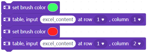
- Affichage de textes dans plusieurs polices à n'importe quelle position.
- Affichage de textes à imprimer dans plusieurs polices.
- Invite à définir la langue du système lorsque CyberPi est démarré pour la première fois.
- Fourniture de plus de langues système, dont le chinois simplifié (简体中文), l'anglais, le chinois traditionnel (繁體中文), le japonais (日本語), le coréen (한국어), l'espagnol (Español), l'italien (Italiano), le français (Français) et l'allemand (Deutsch).
- Fourniture de l'interface pour obtenir la langue du système.
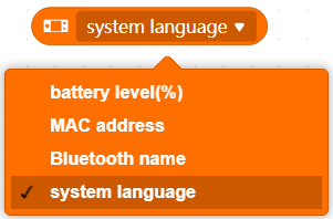
- Reconnaissance des discours des pays et régions courants
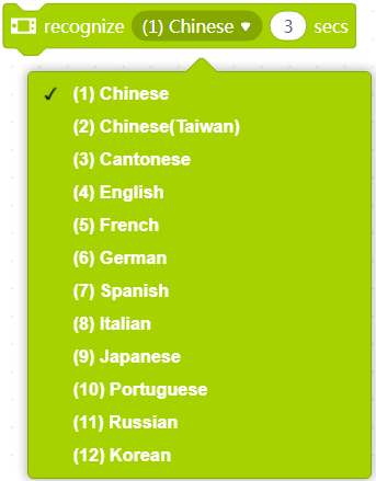
- Traduction de textes dans plus de langues
- Fourniture d'un nouveau mécanisme de charge, permettant une charge plus rapide. Dans cette version, lorsque Pocket Shield et CyberPi sont connectés à un PC ou à un chargeur et que vous éteignez Pocket Shield, CyberPi entre en mode de charge, affichant l'état de charge en temps réel.
- Fourniture du bloc de conversion de type numérique dans la catégorie Opérateurs
3. Fonctionnalités instables
Nous avons également fourni certaines fonctionnalités qui ne sont pas entièrement stabilisées pour permettre aux enseignants et aux élèves de créer des conceptions de base. Des efforts seront déployés pour assurer la compatibilité des versions officielles ultérieures avec les projets créés dans les versions antérieures.
- Fourniture de l'extension et des API Sprites (ne prenant en charge que le mode Téléversement), vous permettant de créer et d'exécuter des applications et des jeux sur CyberPi
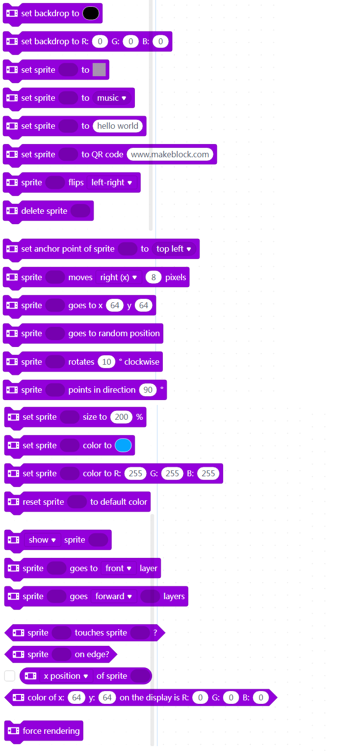
- Fourniture de l'extension et des API Doodle (ne prenant en charge que le mode Téléversement), vous permettant de dessiner des croquis similaires aux dessins Python Turtle sur CyberPi. De plus, les croquis que vous dessinez peuvent être définis comme des sprites et ainsi utilisés dans les applications ou jeux que vous créez.
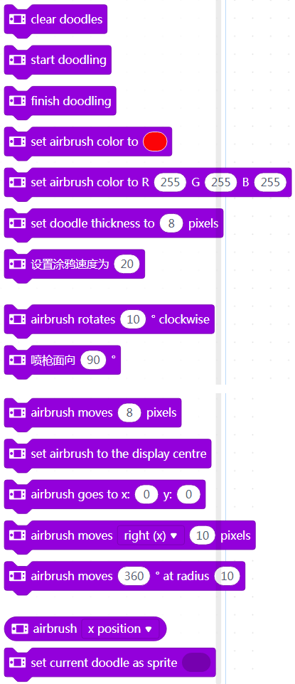
- Annulation de la fonction de connexion Bluetooth. Actuellement, mBlock 5 sur le Web et le client PC mBlock 5 ne prennent pas en charge la connexion Bluetooth de CyberPi en raison du mécanisme de mise en œuvre de mLink 2. Nous pourrions activer cette fonction à l'avenir. Pour activer la connexion sans fil entre CyberPi et mBlock 5, vous pouvez acheter le dongle Bluetooth Makeblock ou utiliser l'application mobile mBlock 5.
Assurance de garantie CyberPi
EnvironmentalProtection and Certification Reports
Contactez-nous
Rejoignez-nous
ChangeHistory
Foreword
Caractéristiques structurelles
Les produits de la série CyberPi sont conçus avec des apparences spéciales, telles que des trous, des trous traversants, des broches et des trous taraudés, qui leur permettent d'être étendus avec d'autres pièces ou composants.
| Conception de l'apparence | Description | |
|---|---|---|
| CyberPi | | Des trous à l'arrière, utilisés pour : |
- se connecter à des cartes d'extension
- se connecter à des blocs Lego ou des pièces métalliques M4 de Makeblock à travers des broches |
| Pocket Shield | | Des broches à l'avant, utilisées pour se connecter à CyberPi |
| | | Des trous et un trou taraudé à l'arrière.
- Les trous sont utilisés pour se connecter à des blocs Lego ou des pièces métalliques M4 de Makeblock à travers des broches.
- Le trou taraudé est utilisé pour se connecter à des pièces métalliques M4 de Makeblock à travers des vis. |
| Modules mBuild | | Des trous traversants, utilisés pour se connecter à des pièces métalliques M4 de Makeblock à travers des broches ou des vis, ou à des blocs Lego à travers des broches |
Voici quelques exemples de connexions courantes :
Exemple 1 : CyberPi + une poutre + deux broches
Exemple 2 : CyberPi + une planche coupée + deux broches
Exemple 3 : Pocket Shield + une plaque en forme de T + une vis M4 x 14
Exemple 4 : CyberPi + Pocket Shield + une plaque en forme de T + deux poutres + cinq vis
Pour plus d'informations sur les pièces métalliques de Makeblock, consultez Pièces mécaniques sur la plateforme Maker.
- Source: Caractéristiques structurelles
Caractéristiques électroniques
Carte de contrôle principale
CyberPi
Cartes d'extension
CyberPi peut fonctionner avec plusieurs cartes d'extension pour répondre à divers besoins éducatifs.
Pocket Shield
Pour plus d'informations sur le Pocket Shield, consultez Pocket Shield.
D'autres cartes d'extension sont en cours de développement. Restez à l'écoute !
Modules électroniques
En plus des modules électroniques mBuild, la série CyberPi prend en charge les composants et pièces électroniques tiers, par exemple, les modules Arduino.
Modules électroniques mBuild
Actuellement, plus de 30 modules électroniques mBuild ont été développés, et d'autres modules seront disponibles.
Chaque module mBuild est équipé d'une puce de microtraitement, ce qui permet à plusieurs modules de se connecter en série à un seul port, comme le montre la figure suivante.
De plus, mBlock 5 peut identifier intelligemment l'adresse des modules, ce qui simplifie votre programmation. Vous n'avez pas à définir les informations sur l'adresse des modules dans l'environnement de programmation lorsque vous ajoutez ou supprimez un module.
Identification intelligente de l'adresse
**Exemple: **
Connecter CyberPi à plusieurs matrices LED
Après avoir connecté CyberPi à plusieurs matrices LED, vous devez uniquement spécifier l'emplacement d'une matrice LED parmi celles connectées au lieu de spécifier le port auquel la matrice LED est connectée lors de la compilation d'un programme. Comme le montre la figure précédente, la première matrice LED connectée à CyberPi est numérotée 1, la deuxième est numérotée 2, et ainsi de suite.
Lorsque vous appuyez sur le bouton A sur CyberPi, la première matrice LED affiche "Hello", et la deuxième affiche "World".
Changez les positions des modules, comme le montre la figure suivante.
Le programme précédent fonctionne toujours après avoir ajouté un capteur de distance. Lorsque vous appuyez sur le bouton A sur CyberPi, la première matrice LED affiche "Hello", et la deuxième affiche "World".
Pour plus d'informations, voir Modules électroniques mBuild.
Capteurs tiers
(Source: Page Web Internet)
La série CyberPi est compatible avec plusieurs capteurs tiers. Vous pouvez consulter les Matériaux open source pour comprendre comment les produits de la série CyberPi sont connectés aux composants électroniques ou pièces tierces.
Moteurs
En travaillant en combinaison avec les modules électroniques ou les cartes d'extension correspondantes, CyberPi peut piloter plusieurs types de moteurs. Le tableau suivant décrit les moteurs pris en charge par CyberPi.
| Support | À travers les modules mBuild | À travers le Pocket Shield | À travers la carte mBot2 | À travers la carte d'extension Challenge |
|---|---|---|---|---|
| Moteur TT 5V | Oui | Oui | Oui | Oui |
| Servo 9g 5V | Oui | Oui | Oui | Oui |
| Servo intelligent 6–12V | Oui | Oui | Oui | Oui |
| Moteur à codeur 12V | Oui | Oui | ||
| Moteur sans balais | Oui | |||
| Moteur pas à pas | Oui |
Autres accessoires
Contrôleur Bluetooth
Les produits de la série CyberPi peuvent se connecter au contrôleur Bluetooth de Makeblock pour l'utiliser comme télécommande. Pour plus d'informations sur le contrôleur Bluetooth de Makeblock, consultez Aide en ligne du contrôleur Bluetooth.
Dongle Bluetooth
Les produits de la série CyberPi peuvent se connecter à des PC en utilisant le dongle Bluetooth de Makeblock. Pour plus d'informations sur le dongle Bluetooth de Makeblock, consultez Guide de démarrage rapide du dongle Bluetooth.
Types de ports
Les produits de la série CyberPi sont conçus avec plusieurs ports, ce qui leur permet de se connecter facilement à d'autres composants électroniques et pièces, facilitant l'extension de nombreuses fonctions.
| Ports | Description | |
|---|---|---|
| CyberPi | | 1: utilisé pour connecter des cartes d'extension |
| 2: utilisé pour connecter des modules électroniques mBuild | ||
| 3: câble USB de type C, utilisé pour connecter un PC | ||
| Pocket Shield | | 1: utilisé pour connecter CyberPi |
| 2: ports de moteurs CC M1 et M2, utilisés pour connecter des moteurs ; ports de servos numériques S1 et S2, utilisés pour connecter des servos ou des bandes LED | ||
| Module électronique mBuild | | Utilisé pour connecter une carte de contrôle principale ou d'autres modules électroniques mBuild |
Les exemples d'extension de fonctions courantes suivent :
Exemple 1: Connexion du Pocket Shield à CyberPi
Le Pocket Shield est équipé d'une batterie rechargeable intégrée qui peut alimenter CyberPi et fournit des ports à 2 broches et 3 broches qui peuvent être utilisés pour connecter des servos, des bandes LED et des moteurs, ce qui améliore considérablement l'extensibilité de CyberPi.
Exemple 2: Connexion des modules mBuild à CyberPi
Les modules mBuild sont petits mais riches en fonctionnalités. CyberPi peut être connecté à plusieurs modules mBuild en connexion série.
Exemple 3: Connexion d'un moteur à CyberPi via le Pocket Shield
CyberPi peut se connecter à plusieurs types de moteurs via d'autres modules ou cartes d'extension.
Câbles
Les produits de la série CyberPi prennent en charge plusieurs types de câbles de connexion, comme décrit dans le tableau suivant.
| Nom | Description |
|---|---|
| Câble USB de type C | Utilisé pour connecter CyberPi à des PC pour l'alimentation ou la transmission de programmes/commandes |
| Câble à 4 broches | Utilisé pour connecter les modules mBuild |
| Câble à 3 broches | Utilisé pour connecter le Pocket Shield ou la carte mBot2 aux bandes LED |
| Utilisé pour connecter les pilotes de LED mBuild aux bandes LED | |
| Câble à 2 broches | Utilisé pour connecter le Pocket Shield ou la carte mBot2 aux moteurs CC |
| Utilisé pour connecter les pilotes de moteurs mBuild aux moteurs CC |
- Source: Caractéristiques électroniques
Programmation de CyberPi sur Chromebook
Installer mLink sur Chromebook et démarrer mBlock 5
Étape 1: Veuillez accéder à ce lien et trouver mLink pour Chromebook (besoin de faire défiler la page vers le bas).
Étape 2: Veuillez cliquer sur "Télécharger" pour accéder au Chrome Web Store, puis cliquez sur "Ajouter à Chrome" pour installer mLink.
:::info
Remarque: Si vous avez déjà installé mLink auparavant, vous verrez directement l'option "Lancer l'application" et vous pouvez contourner l'étape 2.
:::
Ensuite, une fenêtre s'ouvrira, il suffit de cliquer sur "Ajouter l'application", et l'option "Lancer l'application" sera disponible.
:::info
Remarque: Si vous ne trouvez pas l'option "Lancer l'application" après avoir installé mLink, veuillez vérifier si mLink est activé en allant dans "Paramètres"->"Extensions".
:::
Étape 3: Cliquez sur "Lancer l'application" et vous accéderez à la version Web du logiciel mBlock 5 :
Connecter CyberPi à mBlock 5 sur Chromebook
Étape 1: Connectez CyberPi au Chromebook avec un câble USB.
Étape 2: Cliquez sur l'icône "+" pour ouvrir la bibliothèque de périphériques :
Étape 3: Trouvez le périphérique "CyberPi" et sélectionnez-le, puis cliquez sur "Ok" et vous verrez que le périphérique CyberPi est ajouté sous "Périphériques" :
Étape 4: Cliquez sur l'icône "Connecter" et une fenêtre de connexion s'affiche, normalement, le port série pour CyberPi sera disponible automatiquement, veuillez simplement cliquer sur "Connecter" et vous verrez le statut après connexion.
Programmation de CyberPi avec mBlock 5 sur Chromebook
Mode en direct
Étape 1: Assurez-vous que le Commutateur de mode est tiré sur "Live"
Étape 2: Faites glisser un programme simple pour tester CyberPi (ici, je fais simplement glisser le bloc display[][][][][] pour tester les LED sur CyberPi à titre d'exemple).
Étape 3: Cliquez sur le bloc de programme et vous verrez la réaction des LED sur le périphérique CyberPi.
Mode de téléversement
Étape 1: Basculez le Commutateur de mode sur "Upload".
Étape 2: Éditez un programme simple (une tête de programme de la catégorie d'événement est nécessaire) et cliquez sur "Téléverser"
Étape 3: Maintenant, vous verrez la réaction des LED sur le périphérique CyberPi après que le programme a été téléversé avec succès.
- Source: Programmation sur Chromebook
Related Education System
Coming soon!
À propos de CyberOS
CyberOS est le système d'exploitation qui fonctionne sur CyberPi. Il est le composant principal qui prend en charge toutes les fonctions de CyberPi.
Accéder à la page d'accueil de CyberOS
CyberPi fonctionne sous CyberOS. Après la mise sous tension, CyberPi affiche la page d'accueil du système. Si la page d'accueil n'est pas affichée, vous pouvez appuyer sur le bouton Accueil situé sur le côté droit de CyberPi pour y accéder.
Après le démarrage de CyberOS, vous pouvez utiliser les programmes prédéfinis, définir la langue du système et le mettre à jour via Internet.
Vous pouvez quitter la page d'accueil en choisissant "Redémarrer le programme", et le système exécutera automatiquement le dernier programme que vous avez exécuté.
:::info **Note : **Lorsque CyberPi est connecté à mBlock 5 et programmé en mode Live, le bouton ACCUEIL ne fonctionne pas et vous ne pouvez pas accéder à la page d'accueil en appuyant dessus. :::
Définir la langue du système
Si la langue par défaut du système n'est pas votre langue maternelle, vous pouvez la modifier. Les étapes suivantes décrivent la procédure pour changer la langue de l'anglais au chinois :
- Accédez à la page d'accueil, sélectionnez Paramètres en déplaçant le joystick vers le haut ou vers le bas, puis appuyez sur le bouton B pour accéder à la page Paramètres.
- Sur la page Paramètres, sélectionnez Langue en déplaçant le joystick vers le haut ou vers le bas, puis appuyez sur le bouton B pour accéder à la page Langue.
- Sur la page Langue, sélectionnez 简体中文 en déplaçant le joystick vers le haut ou vers le bas, puis appuyez sur le bouton B pour terminer la configuration.
Après avoir défini une langue, le système passe à cette langue et revient à la page d'accueil.
Changer de programme
CyberPi peut stocker plusieurs programmes et vous pouvez passer de l'un à l'autre. De plus, CyberPi est livré avec plusieurs programmes d'exemple par défaut pour vous aider à comprendre ses fonctions principales.
:::info Note :
- L'accès à Internet est requis pour les programmes AI et IoT, ils ne sont donc pas inclus dans les programmes d'exemple par défaut et sont fournis dans les programmes d'exemple sur mBlock 5. Trouvez-les en choisissant Tutoriels > Programmes d'exemple sur mBlock 5.
- Le programme que vous téléchargez sur CyberPi sur mBlock 5 remplace celui que vous avez utilisé la dernière fois. Les programmes d'exemple par défaut sont fournis, et vous pouvez les restaurer en les téléchargeant sur votre CyberPi. :::
- Accédez à la page d'accueil, sélectionnez Changer de programme en déplaçant le joystick vers le haut ou vers le bas, puis appuyez sur le bouton B pour accéder à la page Changer de programme.
- Sur la page Changer de programme, sélectionnez un programme, par exemple Programme1, en déplaçant le joystick vers le haut ou vers le bas, puis appuyez sur le bouton B. CyberPi redémarre et exécute le programme 1.
CyberPi affiche d'abord le nom du programme, puis vous invite à effectuer les étapes requises pour exécuter le programme.
Afficher le niveau de la batterie et l'état de la connexion sans fil
Pour afficher le niveau de la batterie et l'état de la connexion sans fil de CyberPi, vous pouvez vous rendre sur sa page d'accueil et consulter l'icône ou les icônes dans le coin supérieur droit. L'icône du niveau de la batterie indique si la batterie est faible, et une icône Wi-Fi s'affiche si CyberPi est connecté à Internet via Wi-Fi.
Indication de charge
Lorsque CyberPi est en charge via le câble USB (Type-C), CyberOS affiche une indication de charge :
- Si l'interrupteur d'alimentation est allumé, l'indication se trouve dans le coin supérieur droit de l'écran.
- Si l'interrupteur d'alimentation n'est pas allumé, l'indication s'affiche au centre de l'écran et disparaît au bout de 10 secondes pour faciliter la charge rapide.
Mémorisation des paramètres Wi-Fi et mise à jour du micrologiciel OTA
CyberOS enregistre automatiquement les informations sur les réseaux Wi-Fi que vous avez déjà configurés. (Vous pouvez configurer un réseau Wi-Fi sur mBlock 5 ou l'application Makeblock).
Lorsque CyberPi est connecté à Internet, vous pouvez choisir Mettre à jour sur la page Paramètres pour mettre à jour le micrologiciel en mode OTA (Over-The-Air). CyberOS vérifie automatiquement si la version actuelle est la plus récente et vous invite à mettre à jour le micrologiciel si ce n'est pas le cas.
Texte original : https://www.yuque.com/makeblock-help-center-en/cyberpi/cyberos
mBot2 Shield
Présentation
Le mBot2 Shield est équipé d'une batterie lithium-ion rechargeable intégrée qui peut fournir de l'énergie au CyberPi. Avec ses ports multifonctions, servo et moteur, il peut entraîner des moteurs, des servos et des bandes de LED.
Caractéristiques
- Batterie lithium-ion rechargeable intégrée, utilisée pour alimenter le CyberPi
- Deux ports multifonctions, utilisés pour connecter et piloter non seulement des servos mais aussi des bandes de LED
- Deux ports de servo, utilisés pour connecter et piloter des servos
- Deux ports de moteur à courant continu, utilisés pour connecter et piloter des moteurs à courant continu
- Deux ports de moteur encodeur, utilisés pour connecter et piloter des moteurs encodeurs
- Un port CyberPi, vous permettant de connecter facilement le mBot2 au CyberPi
- Prise en charge de la programmation Python, pour laquelle la bibliothèque
cyberpiest fournie
Spécifications
| Spécification | Description |
|---|---|
| Microprocesseur | GD32F403 |
| Batterie | 3,7 V, 2500 mAh |
| Emballage: Pack (batterie incluse) | |
| Type de batterie: Batterie polymère lithium-ion | |
| Poids de la batterie: 44,6 g | |
| Watt-heures par batterie (Wh): 9,25 Wh | |
| Contenu en lithium: 1,07 g | |
| Tension de la batterie au lithium: 3,7 V | |
| Tension d'entrée et courant | 5 V, 2000 mA (charge rapide) |
| 5 V, 500 mA (charge en fonctionnement) | |
| Tension de sortie et courant | 5 V, 6 A |
| Durée de vie de la batterie | 3 à 6 heures (dans des scénarios d'application générale, à titre de référence uniquement) |
| Temps de charge | 80 minutes (en mode charge rapide) |
| Endurance de la batterie | La capacité de la batterie reste à 70% ou plus après avoir été chargée et utilisée 800 fois (à 20±5°C, décharge de 0,2 C). |
| Mode de communication | Communication série: entre la carte de commande principale et la carte d'extension |
| Signaux numériques: au port de servomoteur numérique | |
| Signaux PWM: au port de moteur à courant continu | |
| Version matérielle | V1.0 |
Remarque:
- L'autodécharge se produit dans la batterie lithium-ion. Si vous stockez le mBot2 Shield avec une tension de batterie inférieure à 3,6 V pendant une longue période, la batterie sera surdéchargée et sa structure interne peut être endommagée, ce qui réduit l'endurance de la batterie. Par conséquent, pour stocker le mBot2 Shield pendant une longue période tout en préservant la batterie, vous devez charger la batterie une fois tous les trois à six mois à 3,8–3,9 V (la meilleure tension de stockage est de 3,85 V), ce qui permet la profondeur de décharge de 40 % à 60 %.
- Stockez le mBot2 Shield entre 4°C et 35°C dans un endroit sec ou éloignez-le de l'humidité grâce à l'emballage.
- Gardez-le à l'abri de la chaleur ou du soleil direct.
Programmation
Vous pouvez utiliser mBlock 5 pour programmer le mBot2. mBlock 5 propose deux éditeurs, à savoir l'éditeur graphique basé sur des blocs (l'éditeur par défaut, appelé mBlock 5) et l'éditeur Python (appelé éditeur mBlock-Python).
Pour plus de détails sur la programmation, consultez "Commencer la programmation."
Ramenez Pocket Shield à la maison
- Contactez le revendeur local pour acheter les produits de la série CyberPi et leurs packs éducatifs.
- Contactez-nous pour devenir notre revendeur.
Plus d'informations
Guide d'utilisation de mBot2 Guide d'utilisation de CyberPi
Pocket Shield
Présentation
Le Pocket Shield est équipé d'une batterie rechargeable intégrée qui peut alimenter le CyberPi et fournit des interfaces à 2 et 3 broches pouvant être utilisées pour connecter des servomoteurs, des bandes de LED et des moteurs, ce qui améliore considérablement l'extensibilité du CyberPi.
Caractéristiques
- Batterie LiPo rechargeable intégrée, utilisée pour alimenter le CyberPi
- Deux ports de moteur à courant continu, utilisés pour connecter et piloter des moteurs à courant continu
- Deux ports de servomoteur numériques, utilisés pour connecter et piloter des servomoteurs ou des bandes de LED
- Un port de carte de commande principale, vous permettant de connecter facilement le Pocket Shield au CyberPi
- Prise en charge de la programmation mBlock 5, destinée aux utilisateurs de tous âges, y compris ceux sans aucune expérience en programmation
- Prise en charge de la programmation Python, pour laquelle la bibliothèque
cyberpiest fournie
Spécifications
| Paramètres du produit | Description |
|---|---|
| Microprocesseur | GD32 |
| Paramètre de la batterie | 3,7V 800mAh |
| Tension/courant d'entrée | 5V 700mA |
| Tension/courant de sortie | 5V 2A |
| Durée de vie de la batterie | 4 heures (dans des scénarios d'application générale, à titre de référence uniquement) |
| Temps de charge | 1 à 2 heures |
| Mode de communication | Communication série : entre la carte de commande principale et la carte d'extension |
| Signaux numériques : au port de servomoteur numérique | |
| Signaux PWM : au port de moteur à courant continu | |
| Version matérielle | V1.1 |
| Dimensions | 84×35×19mm |
| Poids | 48g |
Remarque:
- L'autodécharge se produit dans la batterie LiPo. Si vous stockez le mBot2 Shield avec une tension de batterie inférieure à 3,6 V pendant une longue période, la batterie sera surdéchargée et sa structure interne peut être endommagée, ce qui réduit l'endurance de la batterie. Par conséquent, pour stocker le mBot2 Shield pendant une longue période tout en préservant la batterie, vous devez charger la batterie une fois tous les trois à six mois à 3,8–3,9 V (la meilleure tension de stockage est de 3,85 V), ce qui permet la profondeur de décharge de 40 % à 60 %.
- Stockez le mBot2 Shield entre 4°C et 35°C dans un endroit sec ou éloignez-le de l'humidité grâce à l'emballage.
- Gardez-le à l'abri de la chaleur ou du soleil direct.
Mise à jour du micrologiciel
Après la sortie d'une nouvelle version du micrologiciel, vous pouvez connecter le Pocket Shield à mBlock 5 via CyberPi pour visualiser et mettre à jour son micrologiciel. Pour plus de détails sur la mise à jour du micrologiciel, consultez "Comment mettre à jour le micrologiciel ?"
Programmation
Vous pouvez utiliser mBlock 5 pour programmer le Pocket Shield. mBlock 5 propose deux éditeurs, à savoir l'éditeur graphique basé sur des blocs (l'éditeur par défaut, appelé mBlock 5) et l'éditeur Python (appelé éditeur mBlock-Python).
Pour plus de détails sur la programmation, consultez "Logiciel de programmation."
Ramenez le Pocket Shield chez vous
- Contactez le revendeur local pour acheter les produits de la série CyberPi et leurs packs éducatifs.
- Contactez-nous pour devenir notre revendeur.
Plus d'informations
Guide d'utilisation de CyberPi Guide d'utilisation de Pocket Shield Manuel de l'utilisateur de la série CyberPi Documentation API Python pour CyberPi Aide en ligne de mBlock 5 Aide en ligne de l'éditeur Python de mBlock
Fonctions et caractéristiques
Fonctions
Les modules mBuild offrent une variété de fonctions d'entrée et de sortie, vous permettant d'étendre facilement les fonctions des cartes principales prises en charge, telles que CyberPi et Halocode.
Caractéristiques structurelles
Tous les modules mBuild sont développés avec deux trous traversants.
Avec les trous traversants, les modules mBuild peuvent être montés les uns sur les autres avec des connecteurs tels que des broches et des vis. De plus, ils peuvent être connectés à des pièces mécaniques (M4), à des blocs de construction et à d'autres pièces structurales à l'aide de connecteurs. Voici quelques exemples de connexion :
Exemple 1: Haut-parleur + une broche + pilote de servo
Exemple 2: Haut-parleur + une broche + une plaque coupée
Exemple 3: Haut-parleur + une broche + une poutre (M4)
Exemple 4: Haut-parleur + une plaque coupée + deux vis + deux entretoises en laiton
Caractéristiques électroniques
Ports mBuild
La plupart des modules mBuild fournissent deux ports mBuild.
Avec les ports mBuild, plusieurs modules mBuild peuvent être connectés en série.
De plus, l'adresse des modules peut être intelligemment identifiée lorsque vous les programmez sur mBlock 5, ce qui simplifie votre programmation. Vous n'avez pas besoin de définir les informations sur l'adresse des modules lorsque vous ajoutez ou supprimez un module.
Identification intelligente des adresses
Exemple:
Connectez CyberPi à plusieurs matrices LED
Après avoir connecté CyberPi à plusieurs matrices LED, vous devez seulement spécifier l'ordre d'une matrice LED parmi celles connectées au lieu de spécifier le port auquel la matrice LED est connectée lors de la compilation d'un programme. Comme le montre la figure précédente, la première matrice LED connectée à CyberPi est numérotée 1, la deuxième numérotée 2, et ainsi de suite.
Lorsque vous appuyez sur le bouton A sur CyberPi, la première matrice LED affiche "Bonjour", et la deuxième affiche "Monde".
Changez les positions des modules, comme le montre la figure suivante.
Le programme précédent fonctionne toujours après l'ajout d'un capteur de distance. Lorsque vous appuyez sur le bouton A sur CyberPi, la première matrice LED affiche "Bonjour", et la deuxième affiche "Monde".
Port Micro USB
Certains modules mBuild, tels que le Haut-parleur, le Module d'alimentation et la Smart Camera, fournissent un port Micro USB, qui permet à un module de se connecter directement à un ordinateur pour l'alimentation ou la communication.
Pour savoir comment démarrer avec les modules mBuild, consultez Getting Started.
- Original: Functions and Features
Prise en main
Merci d'avoir choisi les modules mBuild !
Si vous utilisez les modules mBuild pour la première fois, lisez attentivement cette page et suivez les instructions pour ne pas manquer leurs fonctions.
Avant d'utiliser les modules mBuild
Connaître le câblage
La plupart des modules mBuild fournissent deux ports mBuild et peuvent donc être connectés à des cartes de commande principales ou à d'autres modules mBuild à l'aide de câbles à 4 broches. Certains fournissent également un port Micro USB, qui permet à un module de se connecter directement à un ordinateur pour l'alimentation ou la communication. Par exemple, après avoir connecté le module haut-parleur à un ordinateur, vous pouvez stocker des fichiers audio sur celui-ci.
La figure suivante montre un câble à 4 broches.
La figure suivante montre un exemple de connexion.
Alimenter les modules mBuild
Vous pouvez alimenter les modules mBuild de l'une des manières suivantes :
Méthode 1 : utiliser le module d'alimentation
Connectez le module d'alimentation aux autres modules à l'aide de câbles à 4 broches. Le module d'alimentation est rechargeable. Vous pouvez le recharger en le connectant à un ordinateur ou à un chargeur.
Méthode 2 : utiliser un ordinateur
Connectez les modules mBuild à une carte de commande principale, telle que Halocode ou CyberPi, à l'aide de câbles à 4 broches, puis connectez la carte de commande principale à un ordinateur.
Commencer à programmer
Avec mBlock 5, vous pouvez programmer les modules mBuild pour implémenter leurs fonctions d'entrée ou de sortie. Les modules mBuild peuvent être programmés en tant qu'appareil ou en tant que modules d'extension d'une carte de commande principale.
Obtenir mBlock 5
Sélectionnez la version applicable à votre appareil. Par exemple, si vous utilisez un PC, vous pouvez télécharger la version pour PC ou utiliser mBlock 5 sur le web.
Programmation par blocs
Programmer les modules mBuild en tant qu'appareil
Dans les étapes suivantes, mBlock 5 sur le web est utilisé.
-
Ouvrez la version web de mBlock 5 sur votre PC.
Choisissez Fichier > Nouveau pour démarrer un nouveau projet.
-
Cliquez sur + ajouter dans l'onglet Appareils et ajoutez mBuild depuis la bibliothèque d'appareils.
-
Connectez les modules mBuild à mBlock 5 via le module Bluetooth.
:::info Note : Pour programmer les modules mBuild en tant qu'appareil, vous devez les connecter à mBlock 5 via le module Bluetooth. :::
(1) Connectez les modules à programmer en série et connectez le module Bluetooth en dernier.
(2) Allumez le module d'alimentation, activez la fonction Bluetooth de votre ordinateur, puis placez le module à proximité de l'ordinateur jusqu'à ce que l'indicateur sur le module Bluetooth reste allumé.
Note : Actuellement, la version web de mBlock 5 sur Windows ne prend pas en charge la connexion du module Bluetooth mBuild à celui-ci via le Bluetooth système. Si votre PC fonctionne sous Windows ou s'il fonctionne sous un autre système mais que le module Bluetooth ne peut pas se connecter à mBlock 5 correctement, vous pouvez utiliser le client PC mBlock 5 (mBlock V5.2.0 recommandé) ou la clé Bluetooth Makeblock. Pour plus de détails sur l'utilisation de la clé Bluetooth Makeblock, consultez la section "Connexion via la clé Bluetooth Makeblock" dans l'aide en ligne de mBlock 5.
(3) Cliquez sur Connecter, choisissez Bluetooth dans la boîte de dialogue qui apparaît, puis cliquez sur Connecter.
Un message s'affiche après que les modules mBuild ont été connectés, indiquant que la connexion est réussie.
Maintenant, vous pouvez faire glisser et déposer des blocs dans la zone de scripts pour compiler votre programme !
Programmes d'exemple
Exemple 1
Lorsque vous appuyez sur la touche Espace, le haut-parleur dit "bonjour" et la matrice LED affiche Bonjour.
Exemple 2
Lorsque vous appuyez sur la touche fléchée vers le haut, les deux pilotes de moteur fournissent de l'énergie ; et lorsque vous appuyez sur la touche Espace, ils cessent de fournir de l'énergie.
:::tips Conseils : Après avoir connecté les pilotes de moteur aux moteurs, vous pouvez contrôler le mouvement des moteurs par programmation. :::
Programmer les modules mBuild en tant que modules d'extension d'une carte de commande principale
Dans les étapes suivantes, Halocode est utilisé en tant que carte de commande principale.
- Cliquez sur + ajouter dans l'onglet Appareils et ajoutez Halocode depuis la bibliothèque d'appareils.
- Connectez Halocode et les modules mBuild à votre ordinateur à l'aide d'un câble Micro USB.
- Cliquez sur Connecter, puis cliquez sur Connecter dans la boîte de dialogue qui apparaît.
Un message s'affiche après que Halocode a été connecté, indiquant que la connexion est réussie.
- Ajoutez les extensions Haut-parleur et Matrice LED.
(1) Ajoutez l'extension Haut-parleur.
(2) Ajoutez l'extension Matrice LED.
Maintenant, vous pouvez faire glisser et déposer des blocs dans la zone de scripts pour compiler votre programme !
Aide sur les blocs
Si vous ne comprenez pas un bloc lors de son utilisation, vous pouvez cliquer avec le bouton droit de la souris dessus et cliquer sur Aide qui apparaît pour afficher ses informations d'aide.
Programmation Python
Vous pouvez également utiliser MicroPython pour programmer les modules mBuild.
Réglez le langage de programmation sur Python.
Pour la documentation de l'API Python des modules mBuild, consultez API Python pour les modules mBuild.
:::tips Conseils : Vous pouvez sélectionner des modules mBuild et les monter ou les installer sur des structures fabriquées à partir de cartes découpées ou de pièces mécaniques selon les besoins. Par exemple, vous pouvez installer les modules de pilote de moteur sur une voiture fabriquée à partir de pièces mécaniques. :::
Plus d'informations
Pour les fonctions et les caractéristiques des modules mBuild, consultez Fonctions et caractéristiques.
- Texte original : https://www.yuque.com/makeblock-help-center-en/cyberpi/get-started
Alimentation
Le module d'alimentation alimente les autres modules mBuild.
Indicateurs
| Allumé | Éteint | |
|---|---|---|
| Indicateur vert | Alimentation allumée | Alimentation éteinte |
| Indicateur rouge | Faible puissance/en charge | Haute puissance/charge terminée |
Spécifications
- Dimension : 48×48mm
- Capacité de la batterie : 950mAh
- Tension de la batterie : 3,7V
- Taux de décharge : 3CC
- Durée de vie de la batterie : 3 heures (valeur de référence uniquement)
- Temps de charge : 1,25 heure
- Tension de sortie : CC 5V
- Courant de décharge : 5V 1,5A, avec une valeur instantanée maximale de 5V 2A
- Courant de protection : 5V 3A (Vous devez connecter le module d'alimentation à un chargeur pour le redémarrer après que la protection a été déclenchée.)
- Tension d'entrée : CC 5V
- Courant d'entrée : <2A
- Température de fonctionnement : 0℃–45℃
- Durée de vie : ≥ 300 cycles de batterie
Précautions
- Lisez attentivement les instructions avant de l'utiliser
- Éloignez-le des sources de chaleur, des endroits à haute tension et ne le heurtez pas ni ne le frappez pendant son utilisation
- Jetez-le correctement et en toute sécurité, et ne le jetez pas dans le feu ou l'eau
- Pendant son utilisation ou son stockage, si le module d'alimentation est chaud, fuit, sent mauvais, est déformé ou dans tout autre état anormal, arrêtez de l'utiliser immédiatement
- Texte original : https://www.yuque.com/makeblock-help-center-en/cyberpi/power
Bluetooth
Le module Bluetooth peut fonctionner avec la clé Bluetooth Makeblock ou tout appareil prenant en charge Bluetooth 4.0, vous permettant de contrôler les modules mBuild sans fil.
Pour les paramètres de connexion Bluetooth, voir "Connexion via Bluetooth 4.0."
Indicateur LED
- Clignotement : non connecté
- Allumé : connecté, fonctionne correctement
- Éteint : éteint ou défectueux
Spécifications
- Dimensions : 24×24 (mm)
- Distance recommandée : moins de 10 m
- Version Bluetooth : BT4.0
- Bande passante : 2402-2480 (MHz)
- Gain d'antenne : 1,5 dBi
- Niveau de consommation d'énergie : ≤4 dBm
- Courant de fonctionnement : 15 mA
- Texte original : https://www.yuque.com/makeblock-help-center-en/cyberpi/bluetooth
Émetteur-récepteur infrarouge
Le module émetteur-récepteur infrarouge peut transmettre et recevoir des signaux infrarouges dans la bande des 940 nm.
Exemples dans la vie réelle
- Climatiseur et sa télécommande
- Téléviseur et sa télécommande
- Voiture télécommandée et sa télécommande infrarouge
Spécifications
- Dimensions : 24 × 24 (mm)
- Bande de fréquence : 940 nm
- Protocole pris en charge : NEC
- Portée de transmission : 6 m
- Portée de réception : 6 m
- Courant de fonctionnement : 40 mA
Bouton
Le module de bouton peut fonctionner comme un déclencheur d'événement, un interrupteur d'état ou un compteur.
Exemples de la vie réelle
- Le bouton d'alimentation est utilisé pour allumer ou éteindre l'ordinateur.
- Le bouton Home de l'iPhone peut être utilisé pour verrouiller ou déverrouiller l'écran.
- Les boutons d'une souris peuvent enregistrer le nombre de fois qu'ils sont pressés.
Spécifications
- Dimensions : 24 × 20 (mm)
- Durée de vie : 100 mille
- Courant de fonctionnement : 15 mA
- Texte original : https://www.yuque.com/makeblock-help-center-en/cyberpi/button
Joystick
Le module joystick peut être utilisé pour contrôler la direction d'un objet en mouvement. Il peut sortir les valeurs des coordonnées x et y auxquelles il est tiré.
La figure suivante montre les plages des coordonnées et la façon dont les directions sont définies.
Exemples de la vie réelle
-
Une manette de jeu utilise des joysticks pour contrôler la direction de déplacement d'un personnage ou son champ de vision.
-
Une télécommande de drone utilise des joysticks pour contrôler la direction de rotation et la vitesse du drone.
Spécifications
- Dimensions : 24 × 36 (mm)
- Durée de vie : 500 mille
- Plage de valeurs de la coordonnée x : –100 à +100
- Plage de valeurs de la coordonnée y : -100 à +100
- Courant de fonctionnement : 15 mA
- Précision de réinitialisation de la position : ±0,2 mm
- Texte original : https://www.yuque.com/makeblock-help-center-en/cyberpi/joystick
Capteur d'angle
Le capteur d'angle est composé d'un encodeur magnétique qui peut détecter la position de rotation avec précision. Contrairement à la molette, le capteur d'angle peut tourner en continu, détectant les degrés de rotation et la vitesse angulaire en temps réel. De plus, le capteur d'angle peut fonctionner avec une variété de plaques pour se connecter à divers composants structuraux et ainsi être appliqué dans différents scénarios.
- Il peut fonctionner avec des pièces mécaniques Makeblock.
- Il peut fonctionner avec des broches Lego.
Principe de fonctionnement
Dans l'électromagnétisme, si nous appliquons une tension aux deux extrémités d'un conducteur rectangulaire, un courant est généré dans une direction. Lorsque cela se produit, si nous appliquons un champ magnétique perpendiculaire au plan du conducteur au conducteur comme indiqué dans la figure suivante, la force de Lorentz est induite, entraînant un décalage de la trajectoire des charges traversant le conducteur.
Selon la règle de la main gauche de Fleming, la direction du décalage peut être déterminée, et la direction de décalage des charges positives est opposée à celle des charges négatives. Ensuite, comme indiqué dans la figure précédente, les charges positives et négatives traversent le conducteur intermédiaire le long de deux chemins différents sur la gauche et la droite, respectivement.
Lorsque cela se produit, une différence de potentiel électrique est générée entre les côtés du conducteur, c'est-à-dire dans une direction perpendiculaire à celle dans laquelle le courant circule. C'est l'effet Hall.
Selon l'effet Hall, nous savons que le courant varie avec le changement du champ magnétique. Par conséquent, si le changement d'un champ magnétique peut être déterminé en fonction du changement de courant et ainsi le changement de position d'un aimant peut être déterminé, alors la position ou la vitesse de rotation d'un arbre équipé d'un aimant peut être détectée.
Exemples dans la vie réelle
- Certains servomoteurs intelligents utilisent des encodeurs magnétiques pour détecter les angles.
- Vous pouvez régler le volume sonore de votre Apple Watch en tournant sa Digital Crown.
Spécifications
- Dimensions : 24 × 36 (mm)
- Précision angulaire : ±1°
- Currant d'utilisation : 22 mA
Module multi-touch
Le module multi-touch est équipé de plusieurs capteurs tactiles, chacun pouvant détecter si le point de contact correspondant est touché. Lorsqu'un point de contact est touché, l'indicateur LED du capteur correspondant s'allume.
Vous pouvez également étendre les points de contact grâce à des crocodiles ou des fil conducteurs, ce qui permet d'utiliser le module multi-touch dans plus de scénarios. Par exemple, vous pouvez utiliser un fil pour connecter un point de contact à une fruits.
Le module multi-touch peut ajustés intelligemment les valeurs de seuil. Chaque fois que le système est mis en marche, tous les seuils sont réinitialisés. De plus, la sensibilité du module multi-touch est programmable. Par exemple, vous pouvez définir la sensibilité sur haute pour implémenter le toucher sans contact.
Fonctionnement
Le module multi-touch fonctionne selon le principe de détection de capacité. Il existe une capacité initiale (Cp) entre un point de contact et terre. Quand un point de contact est touché par vous ou par un autre conducteur, une nouvelle capacité est formée. Lorsque cela se produit, la capacité entre le point de contact et terre change, et l'MCU détermine que le point de contact est touché.
En résumant, la détection du toucher repose sur la détection de changement de capacité, et donc, l'MCU peut détecter le toucher même si aucun point de contact n'est touché.
Exemples réels
- Certains robots sont équipés de capteurs tactils sur leur dos pour détecter si ils sont touchés par les utilisateurs.
- L'écran de votre téléphone portable est un grand et complexe capteur tactile.
Spécifications
- Dimensions: 24 × 72 (mm)
- Courant d'exploitation: 18 mA
Curseur
Le module de curseur peut être utilisé pour contrôler l'entrée.
Principe de fonctionnement
Vous pouvez faire glisser le curseur sur le module de curseur pour changer la résistance et ainsi changer la tension dans le circuit correspondant. Sur la base de la relation entre la tension et la résistance, la résistance peut être calculée et ainsi la position du curseur peut être déterminée.
Exemples de la vie réelle
- Le volume sonore d'un téléphone portable est réglé à l'aide d'un curseur.
- La progression de la lecture vidéo est contrôlée à l'aide d'un curseur.
Spécifications
- Dimensions : 24 × 72 (mm)
- Durée de vie : 15 mille
- Plage de valeurs de sortie : 0–100
- Précision de la valeur : ±2%
- Courant de fonctionnement : 15 mA
- Texte original : https://www.yuque.com/makeblock-help-center-en/cyberpi/slider
Capteur scientifique
Aperçu
Le capteur scientifique est un capteur multifonction développé indépendamment par Makeblock. Intégrant les composants de détection de gaz, de champ magnétique, de flamme, de pression d'air, de température et d'humidité, de PIR, de toucher et d'humidité du sol, le capteur scientifique peut être utilisé dans divers projets de collecte de données, d'exploration scientifique et d'Internet des objets (IoT).
Fonctions et paramètres
| Ensemble | Capteur scientifique | Dimensions : 78,2 × 24 × 1,6 (mm)
Tension de fonctionnement : 5,0 V
Courant de fonctionnement : 250 mA | |
| --- | --- | --- | --- |
| Composants | Nom | Fonction | Paramètre |
| | Capteur de gaz MQ2 | Détecte de manière sensible la fumée, le gaz naturel liquéfié (GNL), le butane, le propane, le méthane, l'alcool et l'hydrogène dans l'air. | - Plage de détection de la concentration de gaz : 300-10000 ppm (gaz inflammable) - Impédance lors du chauffage : 33Ω - Consommation d'énergie de préchauffage : < 950 mW |
| | | Remarque : La déviation peut être importante au moment où le capteur est alimenté. Chauffez-le pendant cinq minutes avant de l'utiliser. | |
| | | | |
| | Capteur de champ magnétique | Mesure l'angle entre l'axe x du capteur de champ magnétique et le pôle Nord (90°N) après étalonnage. | - Plage de détection d'angle : -180° à +180° (L'angle 0° fait référence à 90°N.) - Plage de flux magnétique : ±30G (unité : gauss) |
| | | Remarque : - Placez le capteur sur un plan horizontal avant de l'utiliser. L'incliner peut entraîner une déviation de détection importante. - Assurez-vous qu'aucun matériau magnétique puissant, tel qu'un aimant, n'est placé à proximité. Sinon, des erreurs de détection peuvent se produire. | |
| | | | |
| | Capteur de flamme | Détecte une flamme et sa force par détection de lumière infrarouge. | - Plage de longueur d'onde de détection : 600-1000nm - Plage de force de flamme : 1-100 |
| | | Remarque : N'utilisez pas le capteur en plein soleil. Le soleil peut causer des interférences sévères. | |
| | | | |
| | Capteur de pression d'air | Estime l'altitude en fonction de la pression d'air détectée. | - Plage de détection de la pression de l'air : 300-1100 hPa (unité : centaines de pascals) - Plage de valeurs d'altitude : -500 m à +6000 m |
| | | Remarque : Assurez-vous qu'il n'y a pas de particules, telles que de la poussière, sur la surface du capteur. Sinon, le capteur peut être endommagé. | |
| | | | |
| | Capteur d'humiture | Détecte l'humidité et la température de l'air. | - Plage de valeurs de température : -40°C à +125°C - Erreur de température : - ±0,5°C (dans l'environnement de 0°C à 50°C) - ±1°C (dans l'environnement de -20°C à +85°C) - Plage de valeurs d'humidité : 0-100% - Erreur d'humidité : - ±3% (dans l'environnement de 50% HR) - ±5% (dans l'environnement de 20% à 80% HR) |
| | | Remarque : Assurez-vous qu'il n'y a pas de particules, telles que de la poussière, sur la surface du capteur. Sinon, la déviation de détection peut être importante ou le capteur peut ne pas fonctionner correctement. | |
| | | | |
| | Capteur PIR | Détecte si un être humain ou un animal homéotherme passe. | - Portée de détection : < 2 m - Angle de détection sur l'axe x : 80° - Angle de détection sur l'axe y : 55° - Durée de détection après déclenchement : 2 secondes |
| | | Remarque : Ne retirez pas le filtre Fresnel blanc. Sinon, une déviation de détection importante peut être causée. | |
| | | | |
| | Capteur tactile | Détecte si une main touche le capteur. | - Zone tactile : zone avec l'empreinte digitale - Plage de valeurs de résistance : 0-102300000kΩ |
| | | Remarque : Gardez la zone de l'empreinte digitale claire sans aucune poussière ou goutte d'eau pour éviter les erreurs de détection. | |
| | | | |
| | Capteur d'humidité du sol | Détecte l'humidité du sol. | - Plage de détection : sondes - Plage de valeurs d'humidité : 0-100% (HR) - Plage de valeurs de résistance : 0-102200kΩ |
| | | Remarque : Assurez-vous que la plaque signalétique du capteur scientifique est maintenue au-dessus du sol lorsque vous insérez le capteur dans le sol. Sinon, les autres composants de détection peuvent être endommagés. | |
Programmes d'exemple
Programmes d'exemple pour le capteur scientifique
Exemple 1 : Lampe sensible au PIR (utilisation du capteur PIR)
Vous pouvez contrôler les LED sur CyberPi en fonction du capteur PIR et afficher le résultat de détection du capteur PIR sur l'écran. Pour le principe de fonctionnement du capteur PIR, voir le Principe de fonctionnement du capteur PIR.
Exemple 2 : Détecteur d'environnement (utilisation du capteur d'humiture et du capteur de pression d'air)
Le capteur d'humiture sur le capteur scientifique peut être utilisé pour détecter la température et l'humidité ambiantes, et le capteur de pression d'air peut être utilisé pour détecter la pression de l'air et estimer l'altitude. Vous pouvez programmer l'écran de CyberPi pour afficher toutes les données de sortie des capteurs.
Exemple 3 : Alarme incendie (utilisation du capteur de gaz MQ2 et du capteur de flamme)
Le capteur scientifique intègre un capteur de gaz MQ2 et un capteur de flamme, qui peuvent être utilisés pour détecter les fuites de gaz et les incendies dans les foyers. Avec ces deux capteurs, vous pouvez réaliser une alarme simple qui doit être déclenchée par un gaz inflammable ou une flamme. Lorsque l'alarme est déclenchée, CyberPi émet un son d'avertissement.
Pour le principe de fonctionnement du capteur de flamme, voir le Principe de fonctionnement du capteur de flamme. Le capteur de flamme est déclenché par le rayonnement infrarouge, et le rayonnement infrarouge émis par un corps humain peut également le déclencher. Par conséquent, dans la pratique, vous pouvez définir un seuil (force de la flamme détectée) pour déclencher le capteur de flamme.
Exemple 4 : Boussole (utilisation du capteur de champ magnétique)
Le capteur de champ magnétique sur le capteur scientifique peut être utilisé pour fonctionner comme une boussole. La déclinaison magnétique varie en fonction de la région, et donc vous devez étalonner le capteur de champ magnétique avant de l'utiliser.
:::info
Remarque : Vous devez étalonner le capteur de champ magnétique dans un environnement non magnétique. Un espace extérieur ouvert est recommandé.
:::
Utilisez le bloc suivant pour activer ou désactiver l'étalonnage.
Plage de valeurs de sortie : -180° à +180° (où 0° indique que le capteur scientifique pointe vers 90°N, le pôle Nord)
Programmez le capteur scientifique pour qu'il fonctionne comme une boussole.
Exemple 5 : Détecteur d'humidité du sol (utilisation du capteur d'humidité du sol)
Le capteur d'humidité du sol sur le capteur scientifique est de type résistif. Lorsque l'humidité du sol augmente, l'eau peut dissoudre les ions contenus dans une partie du sol, de sorte que la résistance du sol diminue et que la valeur de sortie du capteur d'humidité du sol devient plus grande. Lorsque la teneur en eau dans le sol augmente encore (dans les cas extrêmes, imaginez que vous jetez du sol dans l'eau), la concentration en ions dans le sol est diluée par l'excès d'eau, ce qui entraîne une diminution de la conductivité électrique et une augmentation de la résistance. C'est pourquoi vous pouvez constater que le capteur d'humidité du sol produit une valeur plus faible dans l'eau pure que dans le sol humide (bien que l'ancien ait une teneur en eau significativement plus élevée) car la concentration en ions dans le sol humide est plus élevée et la résistance est plus faible.
Avec le programme suivant, vous pouvez afficher le changement d'humidité et de résistance du sol détecté par le capteur d'humidité du sol.
Exemple 6 : Lampe à commande tactile (utilisation du capteur tactile)
Le capteur tactile sur le capteur scientifique peut détecter si le point de contact est touché et peut donc implémenter un contrôle basé sur le toucher. Avec le programme suivant, vous pouvez contrôler les LED sur CyberPi en touchant le capteur tactile.
Capteur RGB quadruple
Le capteur RGB quadruple utilise la lumière visible comme source de remplissage, ce qui réduit considérablement les interférences de la lumière ambiante. De plus, il offre la fonction de reconnaissance des couleurs. La nouvelle fonction de calibration de la lumière ambiante réduit également les interférences de la lumière ambiante lors du suivi de ligne. Avec quatre capteurs de lumière, il peut prendre en charge plus de scénarios de programmation.
| Capteur RGB quadruple | Capteur de couleur RGB double | |
|---|---|---|
| Boîtier en plastique pour améliorer la durabilité et la qualité | Oui | Non |
| Capteur de suivi de ligne | 4 | 2 |
| Capteur de couleur | 4 | |
| (qui servent également de capteurs de suivi de ligne) | Non | |
| Capteur de lumière | 4 | |
| (qui servent également de capteurs de suivi de ligne) | Non | |
| Lumière de remplissage | Lumière visible | Lumière infrarouge |
| Calibration de la lumière ambiante pour réduire significativement les interférences de la lumière ambiante | Oui | Non |
Spécifications
Plage de détection : 5–15 mm de l'objet à détecter
Description du bouton
- Double pression : Lorsque le bouton est pressé deux fois, le capteur RGB quadruple commence à apprendre l'arrière-plan et la ligne pour le suivi de ligne.
Placez les capteurs de lumière sur l'arrière-plan de la carte de suivi de ligne et appuyez deux fois sur le bouton. Lorsque vous voyez les LEDs indiquer l'état de suivi de ligne clignoter rapidement, balancez les capteurs de gauche à droite au-dessus de l'arrière-plan et de la ligne jusqu'à ce que les LEDs arrêtent de clignoter. Cela prend environ 2,5 secondes. Les valeurs des paramètres obtenues sont automatiquement stockées. Si l'apprentissage échoue, les LEDs clignotent lentement, et vous devez recommencer l'apprentissage.
- Appui long : Lorsque le bouton est pressé longuement, le capteur RGB quadruple change la couleur des lumières de remplissage. En général, vous n'avez pas besoin de changer la couleur. La couleur est définie automatiquement après que l'apprentissage est terminé.
Guide de programmation
Vous pouvez utiliser mBlock 5 pour programmer le capteur RGB quadruple. Connectez le capteur RGB quadruple à CyberPi, ajoutez CyberPi et connectez-le à mBlock 5, puis ajoutez l'extension Quad RGB Sensor. Pour plus de détails sur la façon d'ajouter CyberPi et de le connecter à mBlock 5 et sur la façon d'ajouter l'extension, voir "Ajouter et connecter mBot2" et "Ajouter des extensions."
Définir le mode de détection
Le capteur RGB quadruple peut être programmé pour détecter l'une des deux options suivantes :
- couleur
- niveaux de gris
Pour la détection des couleurs, le capteur RGB quadruple mesure la lumière réfléchie par un objet en termes de ses valeurs Rouge, Vert et Bleu (RVB). Huit couleurs sont disponibles.
Pour détecter une couleur, vous devez sélectionner une couleur dans le bloc à utiliser, par exemple :
Pour la détection des niveaux de gris, le capteur RGB quadruple mesure l'intensité de la lumière réfléchie par un objet indépendamment de sa couleur.
Pour détecter le niveau de gris, vous devez sélectionner ligne ou arrière-plan dans le bloc à utiliser, par exemple :
Obtenir les valeurs de sortie
Le capteur RGB quadruple peut produire des valeurs basées sur la couleur ou le niveau de gris qu'il détecte, et vous pouvez obtenir ces valeurs en utilisant les blocs reporters, par exemple :
Changer la couleur des lumières de remplissage
Vous pouvez changer la couleur des lumières de remplissage entre vert, rouge et bleu en appuyant longuement sur le bouton ou en utilisant le bloc suivant :
:::info Remarque : Le capteur RGB quadruple peut détecter les couleurs indépendamment des couleurs des lumières de remplissage. :::
Vous devez changer la couleur des lumières de remplissage dans certains scénarios d'application. Pour plus de détails, voir "Scénarios de détection de ligne."
Scénarios de détection de ligne
Avant d'utiliser le capteur RGB quadruple pour détecter des lignes, vous devez effectuer une calibration de base sur celui-ci.
Calibration de base
- Placez les quatre capteurs de lumière du capteur RGB quadruple sur l'arrière-plan et appuyez deux fois sur le bouton du capteur, puis balancez le capteur horizontalement sur la ligne et l'arrière-plan.
- Vérifiez les deux capteurs de lumière au milieu (L1 et R1) du capteur RGB quadruple. Si le robot est sur la ligne, les LEDs bleues des deux capteurs de lumière doivent être éteintes. Les deux LEDs s'allument et s'éteignent alternativement lorsque vous balancez le robot sur la ligne. :::tips Conseils : Le capteur RGB quadruple peut détecter les lignes sombres sur des arrière-plans clairs indépendamment de la couleur de l'éclairage. :::
Les scénarios de détection de ligne suivants décrivent plusieurs scénarios, et les objectifs et blocs recommandés pour chaque scénario.
Scénario 1 : Ligne noire + marge blanche autour de la ligne + fond blanc
Par exemple :
Effectuez une calibration de base sur le capteur RGB quadruple, afin qu'il puisse reconnaître la ligne et l'arrière-plan.
| Niveau | Objectif(s) et bloc(s) recommandé(s) | Remarques |
|---|---|---|
| 1a: débutant |
- Pour déterminer si le capteur RGB quadruple détecte l'état spécifique de la ligne :
- Pour obtenir l'état de la ligne détectée
|
|
| 1b: intermédiaire |
Pour détecter les croisements
| Le capteur RGB quadruple ne peut pas ignorer la ligne, et donc il ne peut pas déterminer si une intersection est réellement un croisement ("+" forme, la ligne réelle continue après la T). Ceci peut seulement être vérifié en roulant droit sur la T et en détectant si la ligne continue. |
| 1c: avancé | Pour mettre en œuvre un suivi de ligne fluide :
| Vérifiez la valeur de sortie de ce bloc.
Changez la couleur des lumières de remplissage pour vous assurer que la valeur de sortie est 0 lorsque le robot est au milieu de la ligne.
La couleur de la lumière de remplissage peut avoir un léger impact sur la valeur de sortie. |
Scénario 2 : Ligne noire avec des sections colorées + marge blanche autour de la ligne + fond blanc
Par exemple :
Les objectifs et blocs recommandés sont les mêmes que ceux du Scénario 1, mais une calibration spéciale est nécessaire.
L'une des méthodes suivantes peut être utilisée :
-
Effectuez la calibration de base sur la couleur la plus claire parmi les sections colorées, par exemple, jaune, de sorte que toutes les couleurs plus sombres soient reconnues comme noires.
-
Effectuez une calibration de base sur la ligne noire, puis appuyez longuement sur le bouton du capteur pour changer la couleur des lumières de remplissage et voir si le capteur reconnaît les différentes sections colorées comme la ligne à suivre.
- section rouge : utilisez les lumières de remplissage vertes ou bleues/blanches
- section jaune : utilisez les lumières de remplissage bleues/blanches
- sections verte et bleue : toutes les lumières de remplissage fonctionnent :::warning Important à savoir :
-
Si vous avez défini la couleur des lumières de remplissage sur mBlock 5, la calibration réinitialise les lumières de remplissage (chaque lumière de remplissage passe rapidement par l'illumination R/G/B).
-
Les sections colorées à l'intérieur de la ligne à suivre peuvent affecter le suivi de ligne avancé et fluide (reconnu comme l'écart par rapport à la ligne). Par exemple, lorsque la calibration de base est effectuée sur la section jaune, la section bleue peut être signalée comme un écart même si elle est à 100% sur la ligne. :::
Scénario 3 : Ligne monocolore + marge blanche autour de la ligne + fond blanc
Par exemple :
Effectuez une calibration de base sur le capteur RGB quadruple, afin qu'il puisse reconnaître la ligne et l'arrière-plan.
Les objectifs et blocs recommandés sont les mêmes que ceux du Scénario 1.
:::info
Remarques :
- Si vous utilisez le bloc de reporting de l'écart, appuyez longuement sur le bouton du capteur RGB quadruple pour changer la couleur des lumières de remplissage pour vous assurer que la valeur de sortie est 0 lorsque vous placez le robot au milieu de la ligne.
- Il n'est pas recommandé d'utiliser le bloc de reporting de l'écart lorsque le contraste entre la ligne et l'arrière-plan est faible. :::
Scénario 4 : Ligne noire + marge blanche autour de la ligne + fond coloré/illustrations
Par exemple :
Effectuez une calibration de base sur le capteur RGB quadruple, afin qu'il puisse reconnaître la ligne et l'arrière-plan.
| Niveau | Objectif(s) et bloc(s) recommandé(s) | Remarques |
|---|---|---|
| 4a: débutant |
- Pour déterminer si le capteur RGB quadruple détecte l'état spécifique de la ligne :
- Pour obtenir l'état de la ligne détectée
|
|
| 4b: intermédiaire |
Pour détecter les croisements :
| Les zones extérieures (arrière-plan) peuvent être reconnues comme la ligne à suivre, en fonction des conditions d'éclairage.
Lorsque cela se produit, vous pouvez utiliser uniquement les capteurs de lumière L1 et R1 pour détecter les lignes, ou vous assurer que la marge blanche autour de la ligne est suffisamment large pour empêcher les capteurs de détecter l'arrière-plan extérieur. |
| 4c: avancé | Pour détecter l'écart par rapport à la ligne :
| Si les couleurs des zones extérieures sont suffisamment proches de la couleur de la ligne à suivre, la valeur de sortie du bloc de reporting de l'écart peut être affectée, et la détection de l'écart peut ne pas être fiable. |
Scénario 5 : Ligne noire + marge blanche autour de la ligne + fond réfléchissant
Par exemple :
Effectuez une calibration de base sur le capteur RGB quadruple, afin qu'il puisse reconnaître la ligne et l'arrière-plan.
Les objectifs et blocs recommandés sont les mêmes que ceux du Scénario 1.
:::info
Remarques :
- L'arrière-plan réfléchissant peut refléter la lumière, ce qui peut affecter la détection de la ligne. Lorsque cela se produit, utilisez une bande de ruban adhésif noire sur les zones réfléchissantes pour améliorer la détection de la ligne.
- Si la ligne n'est pas reconnue, vérifiez si elle est trop réfléchissante et utilisez une bande de ruban adhésif noire pour améliorer la détection de la ligne. :::
Scénario 6 : Ligne noire + marge noire autour de la ligne + fond blanc
Par exemple :
Effectuez une calibration de base sur le capteur RGB quadruple, afin qu'il puisse reconnaître la ligne et l'arrière-plan.
| Niveau | Objectif(s) et bloc(s) recommandé(s) | Remarques |
|---|---|---|
| 6a: débutant |
- Pour déterminer si le capteur RGB quadruple détecte l'état spécifique de la ligne :
- Pour obtenir l'état de la ligne détectée
|
|
| 6b: intermédiaire |
Pour détecter les croisements :
| Les zones extérieures (arrière-plan) peuvent être reconnues comme la ligne à suivre, en fonction des conditions d'éclairage.
Lorsque cela se produit, vous pouvez utiliser uniquement les capteurs de lumière L1 et R1 pour détecter les lignes, ou vous assurer que la marge blanche autour de la ligne est suffisamment large pour empêcher les capteurs de détecter l'arrière-plan extérieur. |
| 6c: avancé | Pour détecter l'écart par rapport à la ligne :
| Si les couleurs des zones extérieures sont suffisamment proches de la couleur de la ligne à suivre, la valeur de sortie du bloc de reporting de l'écart peut être affectée, et la détection de l'écart peut ne pas être fiable. |
Scénario 7 : Ligne noire + marge blanche autour de la ligne + fond réfléchissant + variations de luminosité
Par exemple :
Effectuez une calibration de base sur le capteur RGB quadruple, afin qu'il puisse reconnaître la ligne et l'arrière-plan.
| Niveau | Objectif(s) et bloc(s) recommandé(s) | Remarques |
|---|---|---|
| 7a: débutant |
- Pour déterminer si le capteur RGB quadruple détecte l'état spécifique de la ligne :
- Pour obtenir l'état de la ligne détectée
|
|
| 7b: intermédiaire |
Pour détecter les croisements :
| Les zones extérieures (arrière-plan) peuvent être reconnues comme la ligne à suivre, en fonction des conditions d'éclairage.
Lorsque cela se produit, vous pouvez utiliser uniquement les capteurs de lumière L1 et R1 pour détecter les lignes, ou vous assurer que la marge blanche autour de la ligne est suffisamment large pour empêcher les capteurs de détecter l'arrière-plan extérieur. |
| 7c: avancé | Pour détecter l'écart par rapport à la ligne :
| Si les couleurs des zones extérieures sont suffisamment proches de la couleur de la ligne à suivre, la valeur de sortie du bloc de reporting de l'écart peut être affectée, et la détection de l'écart peut ne pas être fiable. |
Scénario 8 : Ligne monocolore + marge blanche autour de la ligne + fond coloré + variations de luminosité
Par exemple :
Effectuez une calibration de base sur le capteur RGB quadruple, afin qu'il puisse reconnaître la ligne et l'arrière-plan.
Les objectifs et blocs recommandés sont les mêmes que ceux du Scénario 1.
:::info
Remarques :
- L'arrière-plan coloré et les variations de luminosité peuvent affecter la détection de la ligne. Lorsque cela se produit, vérifiez si la couleur de l'éclairage de remplissage est uniforme et si la couleur de la ligne à suivre est suffisamment contrastée par rapport à l'arrière-plan.
- Si la ligne n'est pas reconnue, essayez de changer la couleur des lumières de remplissage et répétez le processus de calibration de base. :::
FAQ
Pourquoi les lumières de remplissage clignotent-elles rapidement sur un mélange de couleurs ?
Lorsque les lumières de remplissage passent rapidement par l'illumination R/G/B, cela signifie que les lumières de remplissage sont réinitialisées. Cela se produit lorsque vous effectuez une calibration de base, et lorsque vous définissez la couleur des lumières de remplissage sur mBlock 5, ce qui peut affecter les valeurs de sortie du capteur RGB quadruple.
Pourquoi le capteur RGB quadruple ne détecte-t-il pas la ligne ?
Si le capteur RGB quadruple ne détecte pas la ligne, vérifiez les points suivants :
- Vérifiez si la ligne est suffisamment contrastée par rapport à l'arrière-plan, et essayez de modifier la couleur des lumières de remplissage.
- Vérifiez si la ligne est trop réfléchissante ou trop sombre. Si c'est le cas, utilisez une bande de ruban adhésif noire sur la ligne réfléchissante pour améliorer la détection de la ligne.
- Vérifiez si la couleur de la lumière de remplissage affecte la valeur de sortie du capteur RGB quadruple.
- Assurez-vous que le capteur RGB quadruple est placé au-dessus de la ligne de manière équilibrée. Si ce n'est pas le cas, il peut ne pas être capable de détecter la ligne.
- Si la ligne est fine ou s'il y a des variations de luminosité dans l'environnement, cela peut affecter la détection de la ligne.
Pourquoi le capteur RGB quadruple détecte-t-il l'arrière-plan extérieur comme la ligne ?
Lorsque l'arrière-plan extérieur est reconnu comme la ligne à suivre, vérifiez les points suivants :
- Vérifiez si la marge blanche autour de la ligne est suffisamment large pour empêcher les capteurs de détecter l'arrière-plan extérieur.
- Vérifiez si les zones extérieures sont suffisamment sombres et si la ligne est suffisamment lumineuse pour être reconnue comme la ligne à suivre.
- Essayez de changer la couleur des lumières de remplissage et répétez le processus de calibration de base.
- Si cela se produit dans des conditions de faible luminosité, augmentez la luminosité de l'environnement.
Pourquoi la détection de l'écart par rapport à la ligne est-elle affectée ?
Si la détection de l'écart par rapport à la ligne est affectée, vérifiez les points suivants :
- Vérifiez si la couleur des zones extérieures est suffisamment proche de la couleur de la ligne à suivre. Si c'est le cas, la valeur de sortie du bloc de reporting de l'écart peut être affectée, et la détection de l'écart peut ne pas être fiable.
- Essayez de changer la couleur des lumières de remplissage et répétez le processus de calibration de base.
- Si la détection de l'écart est affectée par les variations de luminosité, assurez-vous que la luminosité de l'environnement est uniforme.
- Si la détection de l'écart est affectée par des sections colorées dans la ligne, utilisez une autre méthode de calibration pour améliorer la détection de la ligne.
Comment résoudre les problèmes de détection de la ligne dans des conditions de faible luminosité ?
Pour résoudre les problèmes de détection de la ligne dans des conditions de faible luminosité, vous pouvez :
- Augmenter la luminosité de l'environnement en ajoutant des sources de lumière supplémentaires.
- Utiliser des lumières de remplissage plus lumineuses ou changer la couleur des lumières de remplissage.
- Utiliser des bandes de ruban adhésif noires sur les zones réfléchissantes pour améliorer la détection de la ligne.
Ressources
Pour plus d'informations sur le capteur RGB quadruple, voir la page officielle. Pour plus de conseils de dépannage, voir "FAQ."
Capteur ultrasonique 2
Le capteur ultrasonique 2 peut être utilisé pour détecter la distance entre un obstacle et lui. Le transmetteur à gauche émet des ondes ultrasonores, et le récepteur à droite reçoit les ondes ultrasonores réfléchies.
Comparé au capteur ultrasonique que nous avons développé précédemment, le capteur ultrasonique 2 est amélioré dans son boîtier, sa puce et ses LED bleues. Les LED bleues peuvent augmenter le potentiel d'expression émotionnelle et d'interaction.
Comparaison des capteurs ultrasoniques
| Capteur ultrasonique 2 | Capteur ultrasonique | |
|---|---|---|
| Boîtier en plastique pour améliorer la durabilité et la qualité | Oui | Non |
| Puce intégrée pour améliorer la stabilité de fonctionnement | Oui | Non |
| LED bleues (fonction supplémentaire) | 8 | 0 |
Spécifications
- Plage de sortie : 5–300 cm (La valeur de sortie est de 300 lorsque la distance détectée est hors de la plage de sortie.)
- Erreur de valeur de sortie : ±5%
Principe de fonctionnement
Les êtres humains peuvent entendre des sons de 20 à 20 000 Hz. Les ondes sonores avec des fréquences supérieures à 20 000 Hz sont appelées ondes ultrasonores. Les ondes sonores sont renvoyées par les obstacles qu'elles rencontrent et sont reçues par le récepteur du capteur ultrasonique. En se basant sur le temps entre la transmission et la réception, les distances entre le capteur ultrasonique et les obstacles peuvent être calculées.
Exemple de la vie réelle
- Les chauves-souris localisent les objets avec des ondes ultrasonores.
Guide de programmation
Vous pouvez utiliser mBlock 5 pour programmer le capteur ultrasonique 2. Connectez le capteur ultrasonique 2 à CyberPi, ajoutez CyberPi et connectez-le à mBlock 5, puis ajoutez l'extension Capteur ultrasonique 2. Pour plus de détails sur la façon d'ajouter CyberPi et de le connecter à mBlock 5 et sur la façon d'ajouter l'extension, consultez "Ajouter et connecter mBot2" et "Ajouter des extensions".
Détection et détermination de la distance
Pour obtenir la distance entre l'obstacle et le capteur ultrasonique 2, utilisez :
Pour déterminer si un obstacle est trouvé dans la plage de sortie de 5 cm à 300 cm, utilisez :
Généralement, les fonctions de détection et de détermination de la distance sont utilisées pour mettre en œuvre l'évitement des obstacles. Par exemple :
Lorsqu'aucun obstacle n'est détecté dans la plage de détection du capteur ultrasonique 2, mBot2 avance à la vitesse de 100 tours par minute ; lorsqu'un obstacle est détecté, il avance à la vitesse de 50 tours par minute ; et lorsque la distance entre l'obstacle et lui est inférieure à 20 cm, il tourne à gauche.
Expression d'émotions et d'informations
Le capteur ultrasonique 2 est équipé de huit LED bleues. En programmant leur luminosité, vous pouvez utiliser le capteur ultrasonique 2 pour exprimer différents types d'émotions et d'informations.
Exemple 1 :
Après avoir appuyé sur le bouton A, le capteur ultrasonique 2 exprime l'émotion de bonheur en "souriant" lorsque vous le secouez. :::info Remarque : Dans cet exemple, le "sourire" est effectué en allumant les LED bleues aux positions 1, 2, 5 et 6 et en éteignant celles aux positions 3, 4, 7 et 8. :::
Alternativement, vous pouvez utiliser le bloc d'émotion fourni sur mBlock 5 pour exprimer une émotion :
Exemple 2 :
Après avoir appuyé sur le bouton A, placez un obstacle près du capteur
ultrasonique 2, puis éloignez lentement l'obstacle de celui-ci. Vous pouvez voir que les LED bleues deviennent plus lumineuses à mesure que vous éloignez l'obstacle. Une luminosité plus élevée indique une plus grande distance.
- Original: Ultrasonic Sensor 2
Capteur de gaz MQ2
Le capteur de gaz MQ2 peut facilement détecter la fumée, le gaz naturel liquéfié (GNL), le butane, le propane, le méthane, l'alcool et l'hydrogène dans l'air.
Principe de fonctionnement
Le capteur de fumée de type MQ-2 est constitué d'un matériau semi-conducteur d'oxyde d'étain. Lorsqu'il fonctionne à une température de 200 à 300 °C, l'oxyde d'étain adsorbe l'oxygène dans l'air, ce qui réduit la densité des électrons sur le semi-conducteur et augmente ainsi la résistance. Lorsqu'il entre en contact avec de la fumée, si les barrières aux joints de grains sont modifiées par la fumée, la conductivité en surface est modifiée en conséquence. De cette manière, la fumée peut être détectée. Une densité de fumée plus élevée indique une conductivité plus élevée et une résistance de sortie plus faible.
Exemple de la vie réelle
- Une alarme incendie peut détecter la fumée et le gaz inflammable.
Spécifications
- Dimensions : 24 × 36 (mm)
- Courant de fonctionnement : 160 mA
- Impédance lorsqu'il est chauffé : 33Ω
- Consommation d'énergie de préchauffage : < 800 mW
Remarque
L'erreur de détection peut être importante lorsque le module commence à fonctionner. Le module peut être préchauffé pendant cinq minutes pour de meilleures performances.
Capteur magnétique
Le capteur magnétique détecte la présence d'un aimant dans son environnement.
Exemple de la vie réelle
Un robot aspirateur utilise la fonction de détection du champ magnétique dans son mur virtuel pour déterminer s'il peut passer.
Spécifications
- Dimensions : 24 × 20 (mm)
- Distance de détection : <1 cm
- Courant de fonctionnement : 15 mA
Capteur d'humidité et de température
Le capteur d'humidité et de température peut détecter la température et l'humidité dans l'environnement environnant. Vous pouvez l'utiliser pour fabriquer un ventilateur intelligent, un humidificateur intelligent, et ainsi de suite.
Exemple de la vie réelle
- Les appareils domotiques utilisent un capteur d'humidité et de température pour détecter la température et l'humidité, ajustant ainsi les conditions environnementales intérieures.
Spécifications
- Dimensions : 24 × 20 (mm)
- Plage de température : –40 à +125 (℃)
- Erreur de température : ±1℃
- Plage d'humidité : 0–100%
- Erreur d'humidité : ±3%
- Courant de fonctionnement : 15 mA
Capteur de température
Le capteur de température peut détecter la température de l'objet qui entre en contact avec sa sonde.
Avant d'utiliser le capteur de température, connectez-le à la sonde fournie avec celui-ci, comme indiqué dans la figure ci-dessus.
Exemple de la vie réelle
- Un thermomètre électronique utilise un capteur de température.
Spécifications
- Dimensions : 24 × 20 (mm)
- Plage de valeurs : -55 à +125 (℃)
- Erreur de valeur : ±0,5℃
- Courant de fonctionnement : 14 mA
Capteur PIR (Passive Infrared Sensor)
Le capteur infrarouge passif (capteur PIR) peut détecter si une personne ou un animal homéotherme passe à proximité.
Principe de fonctionnement
Le capteur PIR utilise un capteur infrarouge pyroélectrique humain comme composant central. La température normale d'un corps humain est de 37 °C, correspondant à la lumière infrarouge de 10 μm de longueur d'onde. Le capteur PIR détecte le mouvement d'un corps humain ou d'une source de chaleur à proximité en détectant le changement de la lumière infrarouge de 10 μm de longueur d'onde.
Pour détecter de manière sensible le changement de la lumière infrarouge de 10 μm, le capteur PIR utilise un filtre de Fresnel pour concentrer la lumière infrarouge afin que le capteur puisse recevoir autant de lumière infrarouge que possible dans l'environnement.
Exemple de la vie réelle
- Un centre commercial utilise un capteur PIR sur sa porte automatique pour déterminer s'il faut ouvrir ou fermer la porte.
Spécifications
- Dimensions : 24 × 20 (mm)
- Plage de détection : 3–5 (m)
- Plage d'angle de détection sur l'axe x : 80 degrés
- Plage d'angle de détection sur l'axe y : 55 degrés
- Durée de fonctionnement après déclenchement : 3s
- Courant de fonctionnement : 15 mA
Capteur de mouvement
Le capteur de mouvement est composé d'un gyroscope à 3 axes et d'un accéléromètre à 3 axes et peut détecter le mouvement, l'accélération et les vibrations d'un objet.
Axes et angles
| Axe | Nom de l'angle | Plage d'angle |
|---|---|---|
| X | Tangage | –180° à +180° |
| Y | Roulis | –90° à +90° |
| Z | Lacet | –180° à +180° |
Principe de fonctionnement
Si vous recherchez des gyroscopes sur Internet, vous trouverez probablement le schéma suivant.
Il s'agit d'une théorie basée sur la conservation du moment angulaire. Un gyroscope est un mécanisme utilisé pour détecter et maintenir des directions. Il est principalement composé d'un rotor rotatif situé sur l'axe. En raison du moment angulaire du rotor, une fois que le gyroscope commence à tourner, il a tendance à résister au changement de direction. Ces gyroscopes sont utilisés dans les premiers systèmes de navigation.
Dans les produits électroniques modernes, grâce à la technologie microélectromécanique florissante et en raison de la limitation du volume, les gyroscopes basés sur les systèmes microélectromécaniques (MEMS) sont largement utilisés. Ils sont de petite taille et peuvent être directement soudés sur un PCB. C'est pourquoi nous pouvons produire un capteur de mouvement avec des dimensions de 24 × 20 mm.
Les principes de fonctionnement de ces deux types de gyroscopes sont très différents, mais ce que vous devez savoir, c'est qu'ils peuvent refléter de manière plus réaliste la posture et l'état de mouvement d'un objet dans l'espace.
Exemple de la vie réelle
- Le gyroscope utilisé dans la Nintendo Switch vous permet de jouer à des jeux sensoriels.
- L'iPhone utilise un gyroscope pour implémenter sa fonction Niveau.
Spécifications
- Dimensions : 24 × 20 (mm)
- Précision de l'angle:±1 (degré)
- Plage de détection de l'accélération : ±8g
- Courant de fonctionnement : 18 mA
Capteur de flamme
Le capteur de flamme peut détecter une flamme et sa taille en détectant la lumière infrarouge.
La lumière du soleil contient une grande quantité de lumière infrarouge, ce qui peut interférer gravement avec le fonctionnement du capteur de flamme, et donc le capteur de flamme ne peut pas fonctionner correctement lorsqu'il est placé en plein soleil.
Exemple de la vie réelle
- Les capteurs de flamme peuvent être d'une grande aide dans les endroits où le feu est strictement interdit.
Spécifications
- Dimensions : 24 × 20 (mm)
- Plage de valeurs : 0–100
- Erreur de consistance :
- Courant de fonctionnement : 20 mA
Capteur de distance
Le capteur de distance peut détecter la distance entre un obstacle et lui-même en détectant les ondes infrarouges.
Exemple de la vie réelle
- L'iPhone utilise la détection d'ondes infrarouges pour obtenir les structures faciales et les stocker en tant que données biométriques afin de mettre en œuvre la fonction Face ID.
Spécifications
-
Dimensions : 24 × 20 (mm)
-
Plage de valeurs : 2–200 (cm)
-
Précision de la valeur : ±5%
-
Courant de fonctionnement : 33 mA
-
Original: Ranging Sensor
Capteur ultrasonique
Le capteur ultrasonique peut être utilisé pour détecter la distance entre un obstacle et lui. La sonde gauche du capteur ultrasonique émet des ondes ultrasonores et celle de droite les reçoit.
Principe de fonctionnement
Les êtres humains peuvent entendre des sons de 20 à 20 000 Hz. Les ondes sonores avec des fréquences supérieures à 20 000 Hz sont appelées ondes ultrasonores. Les ondes sonores rebondissent sur les obstacles qu'elles rencontrent et sont reçues par la sonde du capteur ultrasonique. En se basant sur le temps entre la transmission et la réception, la distance entre la sonde du capteur ultrasonique et l'obstacle peut être calculée.
Exemple de la vie réelle
- Les chauves-souris localisent les objets avec des ondes ultrasonores.
Spécifications
- Plage de valeurs : 5–300 (cm) (La valeur 300 est rapportée lorsque la valeur dépasse la plage.)
- Erreur de valeur : ±5%
- Courant de fonctionnement : 26 mA
SoundSensor
Capteur de couleur RGB double
Le capteur de couleur RGB double se compose d'une paire d'éléments sensibles à la lumière pour détecter la couleur d'un objet. Il peut faciliter le suivi de ligne des robots tout en détectant les couleurs.
Le capteur de couleur RGB double peut fournir plusieurs types de données, y compris la sortie analogique qui indique l'intensité lumineuse, la sortie numérique qui indique les états de la ligne et de l'arrière-plan, et les valeurs de paramètres calculées pour le contrôle moteur, ce qui garantit une flexibilité suffisante tout en simplifiant votre processus d'application. Sur la base de la sortie des données, les enseignants peuvent expliquer les connaissances et les principes de fonctionnement sous différents aspects.
Le capteur de couleur RGB double fournit la fonction d'apprentissage de carte adaptative. Il définit automatiquement les seuils après avoir appris les couleurs de l'arrière-plan et de la ligne à suivre. Le micrologiciel du capteur comprend un algorithme de suivi de ligne et peut fournir directement des valeurs de paramètres pour contrôler la vitesse de rotation des moteurs, ce qui rend le suivi de ligne à haute vitesse plus facile.
Description des boutons
-
Appui simple : Aucune fonction n'est définie.
-
Double pression : Lorsque le bouton est pressé deux fois, le capteur de couleur RGB double commence à apprendre l'arrière-plan et la ligne pour le suivi de ligne.
Placez les capteurs de lumière sur l'arrière-plan de la carte de suivi de ligne et appuyez deux fois sur le bouton. Lorsque vous voyez les LED indiquant que l'état de suivi de ligne clignote rapidement, balayez les capteurs de côté à côté au-dessus de l'arrière-plan et de la ligne jusqu'à ce que les LED arrêtent de clignoter. Cela prend environ 2,5 secondes. Les valeurs de paramètres obtenues sont automatiquement stockées. Si l'apprentissage échoue, les LED clignotent lentement, et vous devez recommencer l'apprentissage.
- Appui long : Lorsque le bouton est maintenu enfoncé pendant deux à trois secondes, le capteur de couleur RGB double change la couleur des lumières de remplissage dans l'ordre du rouge, du vert et du bleu. En général, vous n'avez pas besoin de changer la couleur. La couleur est définie automatiquement après la fin de l'apprentissage.
Principe de fonctionnement
Chaque groupe de capteurs de couleur se compose d'un capteur de lumière et d'une LED RGB. Dans le monde réel, lorsque vous voyez un objet en rouge, cela signifie que l'objet absorbe plus de lumière que la lumière rouge. Par conséquent, si vous utilisez une lumière de remplissage pour éclairer un objet avec de la lumière rouge, plus l'objet est rouge, plus il réfléchit de lumière, et plus grande est la valeur de sortie du capteur de lumière. De cette manière, vous pouvez obtenir l'intensité rouge de l'objet. De même, vous pouvez changer la couleur des lumières de remplissage pour obtenir l'intensité verte et bleue de l'objet et ainsi déterminer la couleur de l'objet.
Interférences environnementales et erreurs de détection
Dans le monde physique, vous pouvez trouver des interférences environnementales et des erreurs de détection presque partout. Si un capteur de couleur doit déterminer la couleur d'un objet en fonction de l'intensité de la lumière (éclairée par une lumière de remplissage et réfléchie par l'objet) qu'il détecte, des erreurs de détection peuvent être causées car la lumière ambiante est également détectée.
Faites attention aux erreurs de détection. Lorsque vous utilisez deux capteurs de couleur RGB double pour détecter la couleur d'un objet dans le même environnement, les résultats de détection peuvent être différents. Mais en général, la différence est faible.
En pratique, les ingénieurs utilisent des algorithmes ou une conception spéciale pour éviter les interférences environnementales et les erreurs de détection. Par exemple, vous pouvez utiliser une impression 3D pour bloquer la lumière ambiante afin qu'elle n'atteigne pas l'objet à détecter et le capteur de couleur RGB double; alternativement, vous pouvez utiliser un algorithme : enregistrer l'intensité de la lumière ambiante lorsque les lumières de remplissage sont éteintes, et enregistrer immédiatement l'intensité lorsque les lumières de remplissage sont allumées ; puis calculer la différence entre ces deux valeurs d'intensité. Cette différence peut être déterminée comme l'intensité de la lumière de remplissage réfléchie par l'objet. Dans l'algorithme, l'intensité de la lumière ambiante est considérée comme presque inchangée en un très court laps de temps.
Pour les erreurs de détection, vous pouvez également utiliser un algorithme pour classer plusieurs valeurs proches comme une couleur.
Exemple de la vie réelle
- Les capteurs de couleur sont utilisés pour concevoir une ligne d'assemblage pour le tri des pièces.
Spécifications
- Plage de détection : 5–15 (mm) de l'objet à détecter
- Courant de fonctionnement : 70 mA
Capteur de lumière
Le capteur de lumière peut détecter l'intensité de la lumière ambiante.
Principe de fonctionnement
Le capteur de lumière mBuild utilise une photoresistance comme composant central qui peut changer la résistance en fonction de l'intensité lumineuse. Le changement de résistance peut être détecté par le MCU, et donc le MCU peut déterminer l'intensité lumineuse dans l'environnement.
Exemples de la vie réelle
- Un capteur de lumière peut être utilisé pour faciliter le réglage de la luminosité de l'écran d'un téléphone portable.
- Les capteurs de lumière sont utilisés dans certaines lampes intelligentes pour faciliter le réglage de la luminosité en fonction de l'intensité de la lumière ambiante détectée.
Spécifications
- Dimensions : 24 × 20 (mm)
- Plage de valeurs : 0–100%
- Courant de fonctionnement : 15 mA
Capteur d'Humidité du Sol
Le capteur d'humidité du sol peut détecter le niveau d'humidité dans le sol.
Principe de fonctionnement
Il existe deux types courants de capteurs d'humidité du sol, les capteurs capacitifs et les capteurs résistifs. Un capteur d'humidité du sol capacitif mesure le changement de capacité causé par l'humidité du sol pour estimer l'humidité du sol. Un capteur résistif estime l'humidité du sol en fonction de la résistance détectée entre les deux contacts.
La définition stricte de l'humidité du sol est le pourcentage d'eau dans le sol. Ni le capteur d'humidité du sol résistif ni le capteur capacitif ne peuvent prédire avec précision la teneur en eau dans le sol. Ils ne peuvent rapporter que des valeurs d'humidité qui sont positivement corrélées à la teneur en eau.
Le capteur d'humidité du sol mBuild est de type résistif. Lorsque l'humidité du sol augmente, l'eau peut dissoudre les ions contenus dans une partie du sol, de sorte que la résistance du sol diminue, et par conséquent, la valeur de sortie du capteur d'humidité du sol devient plus grande. Lorsque la teneur en eau dans le sol augmente davantage (dans le cas d'extrêmes, imaginez que vous jetez de la terre dans l'eau), la concentration ionique dans le sol est diluée par l'eau en excès, ce qui entraîne une diminution de la conductivité électrique et une augmentation de la résistance. Par conséquent, vous pouvez constater que le capteur d'humidité du sol produit une valeur plus petite dans l'eau pure que dans un sol humide (bien que ce dernier ait une teneur en eau significativement plus élevée) car la concentration ionique dans le sol humide est plus élevée et la résistance est plus faible.
:::tips Remarques : Le capteur d'humidité du sol mBuild est de type résistif, et il peut donc également être utilisé, dans une certaine mesure, pour détecter la résistance. Nous envisageons de développer des ports connexes à cet effet. :::
Spécifications
- Dimensions : 24 × 72 (mm)
- Plage de valeurs : 0–100
- Erreur de consistance : ±5%
- Courant de fonctionnement : 14 mA
- Source originale : Centre d'Aide Makeblock
Caméra Intelligente
La caméra intelligente peut apprendre et reconnaître des objets de couleurs vives ainsi que détecter les codes-barres et les lignes, ce qui lui permet d'être utilisée dans divers scénarios d'application, tels que le tri des déchets, le transport intelligent, le suivi d'objets et le suivi intelligent de lignes.
Connexion à mBot ou Halocode
En fonction du mode de câblage, la caméra intelligente peut être utilisée comme un module électronique RJ25 ou un module électronique mBuild. Après l'avoir connectée à mBot ou Halocode, vous pouvez la contrôler via mBot ou Halocode.
Connexion à mBot
Après avoir connecté la caméra intelligente à mBot, vous pouvez l'alimenter avec une batterie lithium 3,7V ou le module d'alimentation mBuild.
Méthode 1 Alimentation via le module d'alimentation mBuild (recommandée)
Méthode 2 Alimentation via une batterie lithium 3,7V
Connexion à Halocode
Remarque : Il est recommandé d'alimenter la caméra intelligente via le module d'alimentation mBuild. L'alimentation uniquement via le port USB peut affecter l'utilisation correcte du bloc.
Caractéristiques
Apprentissage des couleurs
La caméra intelligente peut apprendre les objets de couleur vive et identifier les blocs de couleur après l'apprentissage, puis renvoyer leurs coordonnées, longueur et largeur. Apprenez un objet coloré comme suit :
- Maintenez le bouton d'apprentissage enfoncé jusqu'à ce que le voyant devienne rouge (orange, jaune, vert, bleu ou violet, différentes couleurs indiquent l'apprentissage d'objets différents), puis relâchez le bouton.
- Placez le bloc de couleur à apprendre devant la caméra.
- Observez le voyant à l'avant ou à l'arrière de la caméra intelligente, et déplacez lentement l'objet à apprendre jusqu'à ce que la couleur du voyant corresponde à celle de l'objet.
- Appuyez brièvement sur le bouton d'apprentissage pour enregistrer l'objet appris actuel. Après que l'apprentissage a réussi, lorsque la caméra reconnaît un objet appris, la couleur du voyant devient la même que celle de l'objet appris.
Un maximum de sept objets peut être appris et enregistré dans ce mode.
| Action | Description |
|---|---|
| Maintien enfoncé jusqu'à ce que la lumière rouge s'allume | Commence à apprendre la couleur 1 |
| Maintien enfoncé jusqu'à ce que la lumière orange s'allume | Commence à apprendre la couleur 2 |
| Maintien enfoncé jusqu'à ce que la lumière jaune s'allume | Commence à apprendre la couleur 3 |
| Maintien enfoncé jusqu'à ce que la lumière verte s'allume | Commence à apprendre la couleur 4 |
| Maintien enfoncé jusqu'à ce que la lumière cyan s'allume | Commence à apprendre la couleur 5 |
| Maintien enfoncé jusqu'à ce que la lumière bleue s'allume | Commence à apprendre la couleur 6 |
| Maintien enfoncé jusqu'à ce que la lumière violette s'allume | Commence à apprendre la couleur 7 |
Après l'apprentissage, vous pouvez utiliser le programme suivant pour suivre le bloc de couleur (bloc de couleur 1).
Remarque
- Plus la couleur de l'objet appris est vive, plus la reconnaissance est précise.
Exemple d'avertissement : apprentissage d'une peluche panda
- La caméra intelligente peut apprendre et enregistrer sept objets, qui doivent être facilement distinguables par leur couleur.
Exemple d'avertissement : apprentissage d'une balle jaune et d'un chapeau jaune
Bon exemple : apprentissage d'une balle orange et d'une balle verte
- Basculez la caméra intelligente en mode détection de blocs de couleur pour détecter les coordonnées et la taille du bloc de couleur.
- La caméra intelligente peut prévenir les interférences lumineuses. Cependant, une lumière changeante peut encore affecter la précision de la reconnaissance. Les résultats d'apprentissage précédents peuvent ne pas réussir à être utilisés dans un nouvel environnement. Voici quelques solutions:
- Réinitialisez la balance des blancs
- Allumez la LED avant l'apprentissage ou la reconnaissance
- Réglez les paramètres détaillés dans PixyMon
- Utilisez un abat-jour pour couvrir les blocs
Reconnaissance de codes-barres et de lignes
La caméra intelligente peut détecter simultanément les codes-barres, les lignes et les routes secondaires sans apprentissage.
Basculez la caméra intelligente en mode suivi de ligne/étiquette pour détecter et renvoyer les informations de coordonnées des codes-barres, des lignes et des routes secondaires.
Reconnaissance des codes-barres
Des cartes et autocollants de codes-barres sont inclus dans le package. Cliquez pour télécharger les cartes de codes-barres.
Vous pouvez placer les cartes sur la carte de suivi de ligne.
Reconnaissance des lignes et des routes secondaires
La caméra intelligente peut détecter les lignes et le nombre de routes secondaires, et renvoyer les coordonnées, directions et le nombre de routes secondaires.
Note
- Vous pouvez définir le mode de suivi de ligne en ligne sombre sur clair ou ligne claire sur sombre dans le programme.
- La caméra intelligente filtrera par défaut les lignes étroites. Consultez le guide de l'utilisateur de PixyMon pour modifier les paramètres par défaut.
PixyMon
La caméra intelligente prend en charge le logiciel PixyMon. Vous pouvez utiliser PixyMon pour afficher l'écran de la caméra, ajuster les fonctions de la caméra intelligente et régler certains paramètres pour explorer des fonctionnalités plus complexes. Suivez les étapes ci-dessous pour installer et utiliser PixyMon :
- Cliquez sur les liens suivants pour télécharger PixyMon. Télécharger PixyMon pour Windows Télécharger PixyMon pour Mac
- Double-cliquez sur le package d'installation et suivez les instructions pour l'installer.
- Après l'installation, ouvrez PixyMon.
- Connectez la caméra intelligente à l'ordinateur via un câble USB.
- Après avoir vu la barre d'état indiquant connecté comme indiqué ci-dessous, vous pouvez commencer à explorer la caméra intelligente avec PixyMon.
Remarque : Pour faciliter l'utilisation du module, nous n'avons pas développé de nombreuses fonctions sur les blocs. Si vous souhaitez contrôler la caméra intelligente via les blocs pour implémenter plus de fonctionnalités, utilisez le Constructeur d'Extensions mBlock 5.
Documentation du Constructeur d'Extensions mBlock
Paramètres
- Dimensions : 48 × 48 (mm)
- Résolution : 640 x 480
- Champ de vision : 65.0 degrés
- Longueur focale effective : 4.65±5% mm
- Vitesse de reconnaissance : 60 ips
- Distance de reconnaissance : 0.25–1.2 (m)
- Résistance à la chute : 1m
- Alimentation : Batterie lithium 3,7V ou module d'alimentation mBuild 5V
- Plage de consommation électrique : 0.9–1.3W
- Température de fonctionnement : -10℃–55℃
Programmes d'exemple
Programmes d'exemple de caméra intelligente
Exemple 1 : Suivi de blocs de couleur 1 – Suivi de la position des blocs de couleur
Dans cet exemple, mBot se déplace en suivant le bloc de couleur spécifié. Les moteurs tournent en fonction de la position du bloc de couleur dans l'image capturée par la caméra intelligente. Ils cessent de tourner lorsque le bloc de couleur est détecté au centre de l'image ou lorsqu'aucun bloc de couleur n'est détecté.
Notez que la manière dont vous installez la caméra intelligente affecte le suivi du bloc de couleur et donc le mouvement de mBot. La figure suivante montre un exemple de la manière dont la caméra intelligente peut être installée.
Détails du programme
Exemple 2 : Suivi de blocs de couleur 2 – Suivi des coordonnées des blocs de couleur
Dans cet exemple, la position (définie comme A) du bloc de couleur dans l'image capturée est obtenue, et la position cible est définie comme B. Les moteurs tournent en fonction de la différence entre A et B, où la différence est calculée en fonction des coordonnées de A et B. De cette manière, un suivi plus précis est effectué. La manière dont mBot se déplace en suivant les coordonnées des blocs de couleur est similaire à celle dont il se déplace en suivant les positions des blocs de couleur.
Détails du programme
Exemple 3 : Suivi de ligne
La caméra intelligente peut reconnaître les segments de ligne. Les moteurs tournent en fonction de la vitesse différentielle calculée en fonction de l'écart du segment de ligne par rapport au centre de l'image capturée.
En mode de suivi de ligne, il est recommandé d'installer la caméra intelligente parallèlement au segment de ligne à reconnaître.
Détails du programme
**Remarque : **
- Kp : Sensibilité dans la prise de virage. Lorsque la vitesse initiale est plus élevée ou que le virage est plus prononcé, un Kp plus grand est nécessaire.
- cible : vitesse initiale
- offset : écart par rapport à la ligne à suivre. Une valeur positive indique un écart vers la gauche de la ligne, et une valeur négative indique un écart vers la droite de la ligne.
Matrice LED bleue 8x16
La matrice LED bleue 8x16 peut afficher des animations, des émoticônes, des textes ou des chiffres. Chaque point de la matrice contient une LED, qui peut être contrôlée individuellement.
Exemple dans la vie réelle
- Les affichages d'informations de vol utilisés dans les aéroports sont d'énormes matrices LED.
Spécifications
- Dimensions : 64 × 44 (mm)
- Courant de fonctionnement : 150 mA
- Texte original : https://www.yuque.com/makeblock-help-center-en/cyberpi/led-matrix
LED RVB
La LED RVB est programmable. Vous pouvez l'allumer dans différentes couleurs et régler sa luminosité par programmation.
Exemples de la vie réelle
- Une LED monochrome est utilisée sur une lampe torche.
- Les LED sont également utilisées dans le clavier d'un ordinateur portable de jeu.
Spécifications
- Dimensions : 24 × 20 (mm)
- Courant de fonctionnement : 15-73 (mA)
- Texte original : https://www.yuque.com/makeblock-help-center-en/cyberpi/rgb_led
Pilote LED
Le pilote LED peut piloter divers accessoires lumineux, notamment des LED, des bandeaux LED et des anneaux LED.
Paramètres
Dimensions : 24 mm × 20 mm Courant de référence : dépend de la charge Accessoires pris en charge : Mini bande LED et anneau
- Texte original : https://www.yuque.com/makeblock-help-center-en/cyberpi/led_driver
Speaker
The speaker can play various preset sounds. You can easily store your audio files in the module and play them through corresponding blocks.
Store user-defined audio files
1. Connect the module to a PC.
Connect the speaker module to a PC by using a Micro USB cable. Use the Micro USB port of the module and a USB port of the PC. After the successful connection, the PC displays the disk of the module, and you can open the disk to view the files stored on it.
2. Store an audio file.
Drag the audio file that you want to play by the speaker to the disk. :::info **Note: **The disk space of the module is limited. It may fail to store a large file. It is recommended that you compass a large file before storing it on the disk. :::
3. Change the file name (# Haut-parleur
Le haut-parleur peut jouer divers sons prédéfinis. Vous pouvez facilement stocker vos fichiers audio dans le module et les lire grâce aux blocs correspondants.
Stockage de fichiers audio définis par l'utilisateur
1. Connectez le module à un PC.
Connectez le module haut-parleur à un PC à l'aide d'un câble Micro USB. Utilisez le port Micro USB du module et un port USB du PC. Après la connexion réussie, le PC affiche le disque du module, et vous pouvez ouvrir le disque pour voir les fichiers qui y sont stockés.
2. Stockez un fichier audio.
Faites glisser le fichier audio que vous souhaitez lire par le haut-parleur sur le disque. :::info Remarque : L'espace disque du module est limité. Il peut échouer à stocker un gros fichier. Il est recommandé de compresser un gros fichier avant de le stocker sur le disque. :::
3. Modifiez le nom du fichier (étape importante).
En raison de la conception matérielle, le module haut-parleur ne peut identifier qu'un fichier audio que par les quatre premiers caractères (lettres anglaises, chiffres ou ponctuations) de son nom de fichier. Pour lire un fichier audio, vous devez changer le nom du fichier au format spécial, c'est-à-dire une combinaison de 4 chiffres de caractères anglais, de chiffres ou de ponctuations. Les exemples suivants décrivent quelques exemples pour vous aider à changer un nom de fichier. Les noms du côté gauche sont les originaux, et ceux du côté droit sont ceux après le changement.
- 龙的传人.mp3 ------------------> ldcr.mp3
- 改革春风吹满地.mp3 ---------> ggcf.mp3
- happy birthday.mp3 ----------> M001.mp3
Après avoir changé les noms des fichiers audio, vous pouvez lire les fichiers audio en utilisant les blocs correspondants sur mBlock 5.
Lecture de fichiers audio définis par l'utilisateur
mBlock 5 fournit les deux blocs suivants pour lire les fichiers audio :
Exemple :
Ce bloc est utilisé pour lire le fichier audio nommé "ldcr" par le premier haut-parleur connecté.
Restaurer les fichiers audio par défaut du haut-parleur
Les mauvais fonctionnements peuvent endommager la bibliothèque de sons prédéfinis, ce qui entraîne l'impossibilité de jouer les sons prédéfinis. Ci-dessous se trouve le dernier package compressé des fichiers audio par défaut. Vous pouvez le télécharger et le décompresser sur le disque du haut-parleur pour remplacer les fichiers endommagés. Suivez ces étapes :
- Connectez le haut-parleur à l'ordinateur avec un câble USB (le haut-parleur est reconnu comme un lecteur USB).
- Formatez le lecteur USB.
- Téléchargez et décompressez le package sons prédéfinis ci-dessous, puis copiez tous ses fichiers audio à la racine de l'USB.
- Sélectionnez 'Éjecter en toute sécurité le lecteur USB' puis débranchez le module haut-parleur de l'ordinateur.
[Preset sounds.rar](https://www.yuque.com/attachments/yuque/0/2021/rar/757912/1618301500291-82ccc3b7-46cb-43b8-9c6d-9911b3122c3f.rar?_lake_card=%7B%22src%22%3A%22https%3A%2F%2Fwww.yuque.com%2Fattachments%2Fyuque%2F0%2F2021%2Frar%2F757912%2F1618301500291-82ccc3b7-46cb-43b8-9c6d-9911b3122c3f.rar%22%2C%22name%22%3 important step). Due to hardware design, the speaker module can identify an audio file only by the first four characters (English characters, numbers, or punctuations) of its file name. To play an audio file, you need to change the file name to the special format, that is, a 4-digit combination of English characters, numbers, or punctuations. The following describes some examples to help you change a file name. The names on the left side are the original ones, and those on the right side are the ones after the change.
- 龙的传人.mp3 ------------------> ldcr.mp3
- 改革春风吹满地.mp3 ---------> ggcf.mp3
- happy birthday.mp3 ----------> M001.mp3
After changing the names of audio files, you can play the audio files by using the corresponding blocks on mBlock 5.
Play user-defined audio files
mBlock 5 provides the following two blocks for playing audio files:
Example:
This block is used to play the audio file named "ldcr" by the first speaker connected.
Restore the default audio files of the speaker
Misoperations may damage the preset sound library, causing the failure to play the preset sounds. Below is the latest compressed package of the default sound files. You can download and decompress it on the disk of the speaker to replace the damaged files. Follow these steps:
- Connect the speaker to the computer with a USB cable (the speaker is recognized as a USB drive).
- Format the USB drive.
- Download and decompress the preset sounds package below and then copy all its audio files to the USB root directory.
- Select 'Safely eject USB drive' and then unplug the speaker module from the computer.
Parameters
- Dimensions: 24 × 36 (mm)
- Total memory size: 16M
- Supported audio format: mp3
- Connector type: Micro-USB
- Rated operating current: 400 mA
Pilote de servomoteur
Le pilote de servomoteur peut piloter tous les types de servomoteurs à 180 degrés, en contrôlant le degré de rotation. Les broches, de gauche à droite, sont définies comme sortie numérique, VCC et GND.
Spécifications
- Dimensions : 24 × 24 (mm)
- Courant de fonctionnement : < 1A
- Texte original : https://www.yuque.com/makeblock-help-center-en/cyberpi/servo-driver
Pilote de moteur
Le pilote de moteur peut piloter divers moteurs CC et vous pouvez l'utiliser pour contrôler la vitesse de rotation et le sens de rotation d'un moteur CC.
Exemples de la vie réelle
- Des pilotes de moteur sont utilisés sur les voitures Tesla.
- Un moteur permet à un sèche-cheveux de sécher vos cheveux avec de l'air.
Spécifications
- Dimensions : 24 × 24 (mm)
- Courant de fonctionnement : < 1A
- Texte original : https://www.yuque.com/makeblock-help-center-en/cyberpi/motor_driver
Contrôleur Bluetooth
En s'associant aux robots, aux cartes de commande principales, aux modules Bluetooth et aux clés Bluetooth de Makeblock, le contrôleur Bluetooth peut être utilisé pour contrôler à distance une gamme de projets.
Le contrôleur Bluetooth est principalement utilisé pour le contrôle de robot dans les sessions manuelles de la compétition de robotique MakeX.
Prise en main
Installation des piles
*Remarques : Lorsque l'indicateur est rouge fixe, cela indique que la batterie est faible et doit être remplacée à temps. *
Appairage Bluetooth
Allumez le contrôleur Bluetooth. L'indicateur clignote lentement en bleu.
Placez le contrôleur à proximité du module Bluetooth du mBot et appuyez sur le bouton jusqu'à ce que l'indicateur clignote rapidement. Relâchez ensuite le bouton et l'appairage est effectué automatiquement.
Ajout d'extensions
Lorsque vous utilisez le contrôleur Bluetooth pour contrôler CyberPi, mBot2, etc., vous devez ajouter les extensions correspondantes sur mBlock5 en premier lieu.
Commencez à programmer
Après avoir ajouté l'extension, vous pouvez écrire des programmes avec les blocs de l'extension, afin de pouvoir contrôler des produits tels que CyberPi et mBot2 avec un contrôleur Bluetooth.
Programmes d'exemple
La version Bluetooth de mBot ne comporte pas de programmes préinstallés pour le contrôleur Bluetooth. Donc, si vous voulez contrôler mBot avec le contrôleur Bluetooth, vous devez écrire un programme dans mBlock5 et le télécharger sur mBot.
Pour plus de détails et de programmes d'exemple sur la façon d'associer et de contrôler mBot avec le contrôleur Bluetooth, veuillez vous référer au fichier ci-dessous. mBot蓝牙手柄代码.zip
| Fonctions du contrôleur Bluetooth | |
|---|---|
| 1.Utiliser le joystick pour déplacer mBot | |
| Déplacer le joystick gauche | mBot se déplace dans la même direction que le joystick et sa vitesse de déplacement dépend de la distance à laquelle le joystick est poussé. |
| 2.Utiliser les boutons pour déplacer mBot | |
| Appuyer sur la touche fléchée ↑ | Avance à une puissance de 100 % |
| Appuyer sur la touche fléchée ↓ | Recule à une puissance de 100 % |
| Appuyer sur la touche fléchée ← | Tourne à gauche à une puissance de 100 % |
| Appuyer sur la touche fléchée → | Tourne à droite à une puissance de 100 % |
| 3.Utiliser les boutons pour faire tourner mBot | |
| Appuyer sur le bouton L1 | Tourne de droite à gauche |
| Appuyer sur le bouton R1 | Tourne de gauche à droite |
| 4.Utiliser les boutons pour contrôler la couleur des LED | |
| Appuyer sur le bouton numéro 1 | Toutes les LED s'allument en rouge |
| Appuyer sur le bouton numéro 2 | Toutes les LED s'allument en vert |
| Appuyer sur le bouton numéro 3 | Toutes les LED s'éteignent |
| Appuyer sur le bouton numéro 4 | Toutes les LED s'allument en bleu |
| Appuyer sur plusieurs boutons numériques | Toutes les LED s'allument en couleur mixte |
| 5.Utiliser les boutons pour contrôler le buzzer | |
| Appuyer sur le bouton L2 | Jouer la note D5 pendant 0,25 temps |
| Appuyer sur le bouton R2 | Jouer la note A3 pendant 0,5 temps |
Spécifications
- Matériau : ABS
- Version Bluetooth : 4.0
- Distance de transmission : 20 m
- Capacité anti-interférence : 80 contrôleurs Bluetooth peuvent fonctionner ensemble sans s'interférer les uns les autres.
- Alimentation : deux piles 5AA
Télécharger le manuel
蓝牙手柄_说明书_十国语言_D1.3.9_KD010194000_View.pdf
Télécommande infrarouge
La télécommande infrarouge peut fonctionner avec le transcepteur IR mBuild. mBlock 5 a fourni le bloc permettant de détecter si une touche de la télécommande infrarouge est pressée.
:::info Remarque : La télécommande infrarouge est alimentée par une pile bouton. En général, elle est livrée avec une pile et vous devez retirer la feuille d'isolation avant de l'utiliser. :::
Spécifications
- Dimensions : 90 × 40 × 12 (mm)
- Bande de fréquence : 940 nm
- Protocole pris en charge : NEC
- Portée de transmission : 8 m
- Alimentation : utilisation d'une pile bouton CR2025
- Durée de vie : plus de 200 mille fois
mBot2 LiPo Rechargeable Battery Enhancement Pack
The mBot2 Lithium-ion Polymer (LiPo) Rechargeable Battery Enhancement Pack is a replaceable battery pack for the MakeX Explorer competition. The pack comes to address the limitations of the insufficient power output and short battery life of mBot2 under high-load scenarios. And you can quickly replenish the power with multiple battery packs.
Specifications
| ** Parameters** | Description |
|---|---|
| Model No. | HL 21700-2P |
| Rated voltage | 3.7V |
| Capacity | 8000mAh |
| Watt hour | 29.6Wh |
Features
- Replaceable; independent charging
- Larger capacity, longer battery life
- Higher power output for scenarios with higher load requirements
Examples
- 原文: https://www.yuque.com/makeblock-help-center-en/cyberpi/mbot2-battery-enhancement# Pack d'amélioration de batterie rechargeable LiPo mBot2
Le pack d'amélioration de batterie rechargeable LiPo mBot2 est un pack de batterie remplaçable pour la compétition MakeX Explorer. Ce pack a été conçu pour pallier les limites de la faible puissance de sortie et de la courte durée de vie de la batterie de mBot2 dans les scénarios à forte charge. Vous pouvez rapidement recharger la batterie avec plusieurs packs de batterie.
Spécifications
| Paramètres | Description |
|---|---|
| Numéro de modèle | HL 21700-2P |
| Tension nominale | 3,7 V |
| Capacité | 8000 mAh |
| Wattheure | 29,6 Wh |
Caractéristiques
- Remplaçable ; charge indépendante
- Capacité plus élevée, durée de vie de la batterie plus longue
- Puissance de sortie plus élevée pour les scénarios avec des exigences de charge plus élevées
Exemples
Adaptateur sans fil
Scénarios d'application
Votre appareil Makeblock ne peut pas se connecter à mBlock 5 directement via Bluetooth si :
- vous utilisez mBlock 5 sur un ordinateur de bureau sans adaptateur Bluetooth ; ou
- vous utilisez mBlock 5 sur un ordinateur portable équipé d'un adaptateur Bluetooth antérieur à Bluetooth 4.0 ou qui n'est pas compatible avec les appareils Makeblock en raison d'exceptions de pilote.
Pour résoudre ce problème, nous vous proposons l'adaptateur sans fil Makeblock. Avec celui-ci, vous pouvez connecter vos appareils Makeblock, tels que CyberPi, Codey Rocky, mBot de la version Bluetooth et mBot Ranger, à mBlock 5 sans fil, et ainsi déboguer les programmes de vos appareils en ligne et télécharger des programmes sur CyberPi, Halocode et Codey Rocky sans fil.
Description de l'indicateur
| Clignote lentement | En veille | Recherche de l'appareil avec lequel il a été apparié la dernière fois et effectue automatiquement l'appariement |
|---|---|---|
| Clignote rapidement | Appariement | Recherche d'un nouvel appareil à appairer avec lui |
| Allumé en permanence | Apparié |
Connexion matérielle
- Ouvrez le capuchon de protection.
- Insérez l'adaptateur sans fil dans un port USB de votre ordinateur.
L'indicateur clignote lentement.
Appariement
Utilisez CyberPi comme exemple (dans cet exemple, Pocket Shield alimente CyberPi)
- Allumez CyberPi.
- Appuyez sur le bouton de l'adaptateur sans fil.
L'indicateur clignote rapidement. L'adaptateur sans fil entre dans l'état d'appariement.
- Placez CyberPi à proximité de l'adaptateur sans fil.
L'appariement est effectué automatiquement.
L'indicateur sur l'adaptateur sans fil reste allumé, indiquant que l'appariement est réussi.
Connexion logicielle
Après qu'un appareil a été appairé avec succès avec l'adaptateur sans fil, vous devez le connecter à mBlock 5 avant de le programmer.
Dans cet exemple, CyberPi est l'appareil à programmer.
Cliquez sur Connecter, sélectionnez le port série utilisé par l'adaptateur sans fil dans la boîte de dialogue qui apparaît, et cliquez sur Connecter.
Un message s'affiche après la connexion de l'appareil, indiquant que la connexion est réussie.
Maintenant, vous pouvez commencer à programmer CyberPi sur mBlock 5 !
Pompe à eau
Avec les câbles de connexion spécifiés, la pompe à eau peut fonctionner avec Pocket Shield, mBot2 et les pilotes de moteur CC.
Lorsqu'elle est pilotée par Pocket Shield, mBot2 ou un pilote de moteur CC, la pompe à eau aspire de l'eau ou souffle de l'air pour contrôler le débit d'eau.
:::info Note :
- La pompe à eau doit être utilisée en combinaison avec un tube qui la supporte.
- La pompe à eau ne peut pas être utilisée dans l'eau. :::
Description de la compatibilité
| Piloté par | Avec | Remarques |
|---|---|---|
| Port moteur CC — Pocket Shield | | Note : Après avoir connecté la pompe à eau à Pocket Shield, mBot2 Shield ou mBuild DC motor driver, réglez la puissance de sortie du port, auquel la pompe à eau est connectée, sur une valeur positive lorsque vous la programmez sur mBlock 5. Sinon, la pompe à eau ne peut pas fonctionner correctement. |
| Port moteur CC — mBot2 Shield | ||
| Pilote de moteur CC mBuild | | |
| Port pilote de moteur CC prenant en charge une tension de sortie de 5 V et un courant de crête de sortie supérieur à 1 A | Connectez-les par soudure ou utilisez un câble de connexion qui prend en charge le pilote |
- Texte original : https://www.yuque.com/makeblock-help-center-en/cyberpi/water_pump
Ventilateur
Avec les câbles de connexion spécifiés, le ventilateur peut fonctionner avec Pocket Shield, mBot2 et les pilotes de moteur CC.
Lorsqu'il est piloté par Pocket Shield, mBot2 ou un pilote de moteur CC, le ventilateur peut tourner dans le sens horaire ou antihoraire pour contrôler la puissance et la direction du vent.
Description de la compatibilité
| Piloté par | Avec |
|---|---|
| Port moteur CC — Pocket Shield | |
|
| Port moteur CC — mBot2 Shield | |
| Pilote de moteur CC mBuild | |
| Port pilote de moteur CC prenant en charge une tension de sortie de 5 V et un courant de crête de sortie supérieur à 1 A | Connectez-les par soudure ou utilisez un câble de connexion prenant en charge le pilote |
- Texte original : https://www.yuque.com/makeblock-help-center-en/cyberpi/fan_package
Servomoteur MS-1.5A
Le servomoteur MS-1.5A a été développé indépendamment par Makeblock. Ses dimensions sont similaires à celles des servomoteurs 9g courants.
Comparaison des fonctionnalités
| Servomoteur MS-1.5A | Servomoteurs 9g plus anciens | |
|---|---|---|
| Hub de servomoteur monté avant livraison | Oui | Non |
| Prise en charge de l'assemblage rapide | Oui | Non |
| Compatible avec les pièces métalliques Makeblock et les blocs Lego | Oui | Oui, mais des supports d'adaptation sont nécessaires |
| Limite physique | Non (Les circuits ont été redessinés pour mieux protéger le servomoteur et ainsi garantir une durée de vie plus longue.) | Oui |
Exemple de connexion
Dimensions (en millimètres)
Spécifications
Grâce à la technologie la plus récente dans l'industrie des servomoteurs, le servomoteur MS-1.5 offre des performances considérablement améliorées. Les spécifications suivantes sont décrites ci-dessous.
Spécifications électriques (paramètres de performance)
| Élément | 4,6 V | 6,0 V |
|---|---|---|
| Vitesse de fonctionnement (sans charge) | 0,11 ± 0,01 sec/60° | 0,10 ± 0,01 sec/60° |
| Courant de fonctionnement (sans charge) | 270 mA ± 50 mA | 380 mA ± 50 mA |
| Couple de blocage (verrouillé) | 1,5 kg ± 0,30 kg·cm | 1,8 kg ± 0,30 kg·cm |
| Courant de blocage (verrouillé) | 1200 mA ± 50 mA | 1500 mA ± 70 mA |
| Courant d'arrêt (arrêté) | 4 mA ± 1 mA | 4 mA ± 1 mA |
| Durée de vie (sans charge) | > 180 mille fois | > 150 mille fois |
:::info Note : Le servomoteur fonctionne sans charge lorsque la valeur moyenne de l'élément 2 est définie. :::
Spécifications mécaniques
| Élément | Spécification |
|---|---|
| Dimensions globales | Voir "Dimensions." |
| Angle limite | Non |
| Poids | Selon le poids réel |
| Spécification du fil | JST 2,54 mm #30 PVC noir-blanc-rouge |
| Longueur du fil | 260 ± 5 mm (connecteurs non inclus) |
| Spécification de la corne | 20T |
| Type de corne | Sans objet |
| Jeu excessif | ≤ 1° |
Spécifications de contrôle
| Élément | Spécification |
|---|---|
| Système de contrôle | Sans objet |
| Type d'amplificateur | Sans objet |
| Course de fonctionnement | 180°± 5° (500 à 2500 µ sec) |
| Écart angulaire gauche-droite | ≤ 5° |
| Écart de centrage | ≤ 1° |
| Position neutre | Sans objet |
| Largeur de bande morte | Sans objet |
| Sens de rotation | Sens inverse des aiguilles d'une montre (500 à 2500 µ sec) |
| Plage de largeur d'impulsion | 500 à 2500 µ sec |
| Course maximale | Environ 180° (500 à 2500 µ sec) |
- Texte original : https://www.yuque.com/makeblock-help-center-en/cyberpi/ms-1.5a_servo
Servo 9g Micro (engrenage métallique)
Le servo 9g Micro (engrenage métallique) de Makeblock est un servo de haute qualité personnalisé par Makeblock. Il peut être livré assemblé ou non assemblé dans un pack, comprenant les quatre éléments suivants : servo 9g micro (engrenage métallique), corne de servo, vis et support de servo.
Dimensions
Spécifications
| Spécifications électriques | ||
|---|---|---|
| Élément | 4,8 V | 6,0 V |
| Vitesse de fonctionnement (sans charge) | 0,15±0,015 sec/60° | 0,13±0,015 sec/60° |
| Courant de fonctionnement (sans charge) | 80±35 mA | 90±35 mA |
| Charge maximale en fonctionnement | 1,0±0,05kg·cm | 1,1±0,1kg·cm |
| Couple de blocage (verrouillé) | 1,5±0,05kg·cm | 1,8±0,1kg·cm |
| Courant de blocage (verrouillé) | 680±40 mA | 750±50 mA |
| Courant d'arrêt (arrêté) | 6±1 mA | 6±1 mA |
| Dérive de température (à 25°C) | ≤5° | ≤7° |
| Spécifications mécaniques | ||
| Dimensions globales | Voir "Dimensions". | |
| Angle limite | 180°±10° | |
| Poids | 13,5±0,5g | |
| Section du fil de connexion | #28 PVC, noir-rouge-blanc, fiche : 2510-3P, blanc | |
| Longueur du fil de connexion | 260±5 mm | |
| Fente de l'engrenage de la corne | 40T | |
| Type de corne | Double bras | |
| Rapport de réduction | 1/324 | |
| Jeu excessif | ≤1° | |
| Vis | PM2×5 mm | |
| Spécifications de contrôle | ||
| Système de contrôle | Modification de la largeur d'impulsion | |
| Type d'amplificateur | Contrôleur analogique | |
| Course de fonctionnement | 180°±10° (600 à 2400 µ sec) | |
| Écart angulaire gauche et droite | ≤7° | |
| Écart de centrage | ≤1° | |
| Position neutre | 1500 µ sec | |
| Largeur de bande morte | ≤7 µ sec | |
| Sens de rotation | Sens inverse des aiguilles d'une montre (1500 à 2000 µ sec) | |
| Plage de largeur d'impulsion | 500 à 2500 µ sec | |
| Course maximale | Environ 190° (500 à 2500 µ sec) |
Moteur TT haute vitesse
Le moteur TT haute vitesse Makeblock est un moteur à engrenages en plastique lancé par Makeblock. Vous pouvez utiliser des moteurs TT haute vitesse en combinaison avec des poulies de transmission en plastique Makeblock 62T ou 90T pour construire des mécanismes de roues dans les compétitions MakeX ou divers projets DIY.
Spécifications
| Élément | Description |
|---|---|
| Référence | M2010003000 |
| Tension nominale | 6V CC |
| Tension de fonctionnement | 4-8 V CC |
| Courant sans charge | ≤220mA |
| Courant avec charge nominale | ≤260mA |
| Vitesse de rotation sans charge | 15000 tr/min ±10% |
| Vitesse de rotation avec charge nominale | 310 tr/min ±10% |
| Rapport de démultiplication | 1 : 48 |
| Température et humidité de fonctionnement | -5℃ à + 40℃ ; 15%HR-90%HR |
| Température et humidité de stockage | -10℃ à +50℃ ; 15%HR-90%HR (sans condensation) |
Structure et dimensions
- Texte original : https://www.yuque.com/makeblock-help-center-en/cyberpi/high-speed-tt
Moteur TT à double arbre
Le moteur TT à double arbre Makeblock est un moteur à engrenages en plastique à courant continu qui fournit une sortie à double arbre. Il prend en charge les ports de moteur CC des cartes d'extension de la série CyberPi et peut être utilisé dans divers projets DIY pour entraîner la rotation de toutes les pièces (comme les roues) connectées à ses arbres.
Spécifications
| Élément | Spécification |
|---|---|
| Tension nominale | CC 6 V |
| Vitesse sans charge | 200 tr/min ± 10 % |
| Rapport de démultiplication | 1:48 |
Caractéristiques
- Fournit une sortie à double arbre
- Prend en charge la rotation positive et négative
- Fournit un contrôle de haute précision
- Conçu avec une structure simple, promettant un entretien peu coûteux
Structure et dimensions
Exemple
- Texte original : https://www.yuque.com/makeblock-help-center-en/cyberpi/tt-dual-shaft
Moteur à encodeur optique 180
Vue d'ensemble
Le moteur à encodeur optique 180 est équipé d'un encodeur optique qui permet un contrôle de haute précision. Avec deux trous filetés M4 sur chacun des trois côtés, il peut être facilement connecté à des pièces mécaniques Makeblock et ainsi être utilisé de manière flexible en combinaison avec diverses autres pièces. Le matériau personnalisé qu'il utilise réduit le bruit et garantit un couple de sortie élevé. Il prend en charge plusieurs pilotes de moteur et cartes de contrôle principales, tels qu'Orion, MegaPi, MegaPi Pro, Me Auriga et mBot2 Shield.
Performances électriques
| Tension d'alimentation | 5V | 7.4V |
|---|---|---|
| Plage de vitesse de rotation | 1-207 (tr/min) | 0-350 ± 5% (tr/min) |
| Précision de rotation | ≤ 5° | |
| Précision de détection | 1° | |
| Couple de rotation | 1 500 g·cm | Couple de démarrage : 5 000 g·cm |
| Couple nominal : 800 g·cm | ||
| Matériau de l'arbre de sortie | Métal |
Performances de contrôle
| Tournant | Tournant précis |
|---|---|
| Avançant droit | Écart : ≤2% |
| Fournir la commande pour avancer de XX mm | |
| Fonctionnant comme un servomoteur | Pris en charge |
| Précision de contrôle d'angle : ≤5° | |
| Fonctionnant comme une molette | Pris en charge |
| Précision de détection : 1° |
Spécifications mécaniques
- Rapport de réduction de l'engrenage : 39,6
- Longueur de l'arbre de sortie : 9 mm
- Texte original : https://www.yuque.com/makeblock-help-center-en/cyberpi/photoelectric-encoder-motor-180rpm
Bandeau LED (0,5 m et 1 m)
Vue d'ensemble
Le bandeau LED (adressable, étanche) est composé de plusieurs LED RVB adressables. Le bandeau LED RVB de 1 mètre comprend 30 LED RVB. En plus des caractéristiques de haute luminosité et de couleur complète, vous pouvez également contrôler la couleur et la luminosité de chaque LED RVB individuellement via la programmation.
Spécifications
- Longueur du câble : 1 m, 0,5 m
- Tension de fonctionnement : 5V CC
- Courant de fonctionnement : 1,8 A/m (courant maximum)
- Température de fonctionnement : -40 à +60°C
- Angle visible : >140°
- Durée de vie : > 50 000 heures
- Dimensions : 1000 x 13 x 3 mm (L x l x H), câble non inclus
Caractéristiques
- Fourniture de 256 niveaux de luminosité et de 16 777 216 couleurs pures
- Correspondance complète avec la bibliothèque Arduino pour faciliter la programmation
- Permettant de contrôler chaque LED individuellement
- Permettant de changer la forme du bandeau LED pour réaliser différents motifs lumineux
- Texte original : https://www.yuque.com/makeblock-help-center-en/cyberpi/led-strip
Mini bande LED et anneau
En raison du port physique et des protocoles de contrôle, la mini bande LED et l'anneau ne peuvent fonctionner correctement qu'avec le pilote LED mBuild. L'utilisation d'un pilote tiers pour piloter la mini bande LED ou l'anneau peut entraîner une déviation de couleur.
Bande LED
La bande LED peut être utilisée pour fabriquer une épée lumineuse ou des mots lumineux, ou pour créer une ambiance.
Lors de l'utilisation de la bande LED, connectez la prise IN au pilote LED ou à la prise OUT d'une autre LED, d'une bande LED ou d'un anneau LED.
La bande LED n'est pas étanche. Son utilisation dans l'eau peut l'endommager et ce type de dommage n'est pas couvert par la garantie.
Paramètre
- Dimensions : 8 mm × 112 mm
Anneau de 12 LED
Lors de l'utilisation de l'anneau LED, connectez la prise IN au pilote LED ou à la prise OUT d'une autre LED, d'une bande LED ou d'un anneau LED.
L'anneau LED n'est pas étanche. Son utilisation dans l'eau peut l'endommager et ce type de dommage n'est pas couvert par la garantie.
Les emplacements des LED sur l'anneau de 12 LED sont définis de la même manière qu'une horloge, comme indiqué dans la figure suivante.
Paramètre
- Dimensions : diamètre de 45 mm
Description de la compatibilité
| Piloté par | Avec |
|---|---|
| Pilote LED mBuild | |
Adaptateur M4
L'adaptateur M4 est utilisé pour connecter des modules mBuild à d'autres pièces avec des trous M4 ou pour assembler des modules mBuild ensemble.
Exemples de connexion
Exemple 1
Exemple 2
Câble universel 5V
Le câble universel 5V est utilisé pour connecter les modules mBuild ou connecter les modules mBuild à tout contrôleur principal compatible avec les modules mBuild. Actuellement, des câbles mBuild de 10 cm, 20 cm et 60 cm sont disponibles.
Si vous avez besoin d'un câble mBuild d'une autre longueur, vous pouvez combiner différents câbles avec le module d'extension.
Module d'extension
Le module d'extension peut être utilisé pour connecter deux câbles universels 5V afin de former un câble plus long.
Exemple de connexion
Doodle Boy (Détails de la fonction Doodle en détail)
1. Avant de commencer
- Les fonctions et programmes Doodle décrits dans cet article sont basés sur la version 006, assurez-vous que vos environnements matériels et logiciels sont de la version 006 ou supérieure.
- Ouvrez mBlock5, ajoutez CyberPi à la bibliothèque, sélectionnez Extension, et ajoutez l'extension Display+.
- Consultez le Guide d'exploitation de l'extension "Display+" pour CyberPi pour plus de détails.
2. Qu'est-ce que Doodle
Doodle est une fonction de l'extension Display+ qui émule les graphiques turtle en Python. C'est comme dessiner sur du papier avec un stylo. Dans mBlock5, nous pouvons utiliser les blocs Doodle pour contrôler l'épaisseur du trait, les coordonnées, et d'autres paramètres pour afficher des motifs personnalisés sur CyberPi.
3. Pour commencer
3.1 Commencer à dessiner
3.1.1 Ajouter Display+
Ajoutez CyberPi à la bibliothèque de périphériques et ajoutez l'extension "Display+", vous pouvez alors voir les catégories Sprites et Doodle comme illustré ci-dessous. Connectez CyberPi à l'ordinateur et vous pouvez commencer à programmer.
_Remarque : Doodle ne peut être utilisé qu'en mode Téléversement
3.1.2. Entraînement avec exemple
Pour commencer à dessiner après avoir ajouté le bloc d'événement, vous devez également ajouter le bloc "Commencer à dessiner". Avant de commencer, vous pouvez définir l'épaisseur, la couleur et la position de départ du pinceau. Seulement en déplaçant le pinceau crée un chemin, tandis que la rotation ne laisse pas de trace sur l'écran. Après avoir fini de dessiner le motif, vous devez ajouter le bloc "Terminer le dessin" pour terminer le programme.
Voyons maintenant comment dessiner une ligne sur l'écran.
Pseudocode
Blocs
3.1.3 Téléverser le programme
Téléversez le programme sur l'appareil connecté et vous pouvez afficher le dessin sur l'écran.
3.2 Utiliser le pinceau
Le pinceau est très important dans les blocs Doodle. Il fonctionne comme un pinceau pour dessiner des motifs sur l'écran. Vous pouvez utiliser les blocs Doodle dans mBlock5 pour déplacer, faire pivoter et positionner le pinceau, et vous pouvez utiliser des fonctions et des variables pour créer des motifs graphiques plus complexes.
Fonctions du pinceau
Vous pouvez utiliser les blocs pour ajuster la direction et les coordonnées du pinceau et pour définir le nombre de pixels qu'il se déplace. Pour dessiner des graphiques avec Doodle, vous devez utiliser les blocs pinceau.
Blocs du pinceau
| Fonction | Blocs | Description |
|---|---|---|
| Couleur | | Vous pouvez définir la couleur du pinceau de deux manières : |
- Sélectionnez la couleur via la palette de couleurs.
- Définissez les valeurs RGB, de 0 à 255, c'est-à-dire de la lumière minimale à la lumière maximale. |
| Mouvement linéaire | |
Le pinceau se déplace en pixels pour dessiner une ligne droite. La direction est par défaut vers la droite.
|
| Mouvement de rotation | |
Vous pouvez définir le rayon et l'angle pour dessiner des cercles ou des arcs de tailles différentes.
|
| Angle de rotation | | Vous pouvez ajuster l'angle du pinceau de deux manières :
- Cliquez sur la boîte de saisie pour révéler le cadran et faites glisser la flèche pour ajuster l'angle. Ici, le pinceau pointe dans la direction 90°, parallèle à la direction positive de l'axe X.
- Entrez un degré spécifié par lequel le pinceau tourne dans le sens des aiguilles d'une montre. La flèche du pinceau fait face à droite par défaut et change après chaque ajustement d'angle. La direction de l'angle que vous voyez est celle après le dernier ajustement. |
| Positionnement | | Vous pouvez définir le point de départ du pinceau de trois manières :
- Réglez-le au centre de l'écran
- Déplacez-le aux coordonnées spécifiées. Ici (0,0) est sur le sommet de l'angle droit dans le coin supérieur gauche de l'écran.
- Ajustez les paramètres. |
4. Aide aux blocs
Si vous avez des questions lors de l'utilisation du bloc, vous pouvez cliquer avec le bouton droit sur le bloc et sélectionner Aide dans le menu.
Alternativement, vous pouvez consulter l'aide aux blocs pour Display+.
5. Programmes d'exemple
Balle Doodle
Battement de cœur ECG
Course de balle de blocage
Suivi de ligne avec Kp
Comment le capteur quad RGB réagit-il lorsqu'il détecte une ligne?
Les quatre indicateurs du capteur quad RGB vous aident à savoir rapidement ce que le capteur a détecté : lorsque l'arrière-plan est détecté, l'indicateur s'allume ; sinon, l'indicateur ne s'allume pas.
Par défaut, le capteur quad RGB identifie les couleurs plus claires comme des arrière-plans et les couleurs plus sombres comme des lignes.
Comment le capteur différencie-t-il une ligne d'un arrière-plan?
Le capteur quad RGB possède 4 sondes capables de détecter l'intensité lumineuse. Elles fonctionnent en détectant activement l'intensité de la lumière réfléchie après que la lumière de remplissage ait éclairé l'objet.
Le capteur peut déduire la valeur de gris de l'objet. Plus la valeur de gris est élevée, plus l'objet est lumineux, sinon il est plus sombre.
Pour distinguer la ligne de l'arrière-plan, nous devons également donner au capteur une valeur de seuil, indiquant au capteur que les couleurs au-dessus ou en dessous de ce seuil sont des couleurs d'arrière-plan, sinon ce sont des lignes. De cette manière, le capteur peut distinguer les arrière-plans des lignes.
Par défaut, nous définissons une valeur de seuil uniforme pour le capteur quad RGB, afin que vous puissiez l'utiliser dès la sortie de la boîte.
Valeur de seuil par défaut
Vous pouvez également définir une nouvelle valeur de seuil ou définir des couleurs sombres comme arrière-plans en apprenant.
Permettez au capteur d'apprendre une nouvelle ligne et un nouvel arrière-plan avec le bouton d'apprentissage
Dans les concours, nous utilisons souvent des cartes de suivi de ligne avec des lignes blanches sur un fond noir (ce qui rend la carte plus durable) ou d'autres combinaisons de couleurs d'arrière-plan et de lignes. Dans ces cas, nous devons utiliser la fonction de calibrage du capteur quad RGB.
La fonction apprentissage permet au capteur quad RGB de trouver la couleur de la lumière de remplissage et la valeur de seuil qui correspondent le mieux à la lumière ambiante actuelle, à la couleur d'arrière-plan et à la couleur de la ligne. Les méthodes sont les suivantes.
-
Double clic : déclenche l'apprentissage du suivi de ligne.
- Placez les deux sondes du capteur sur l'arrière-plan de la carte de suivi de ligne, et double-cliquez sur le bouton apprentissage.
- Lorsque vous voyez les deux indicateurs de suivi de ligne clignoter rapidement, à une hauteur fixe sur l'arrière-plan, secouez le capteur jusqu'à ce que les indicateurs arrêtent de clignoter rapidement (cela prendra environ 2,5 secondes).
- Les paramètres d'apprentissage seront automatiquement enregistrés. Si l'apprentissage échoue, les deux indicateurs de suivi de ligne passeront en clignotement lent et vous devrez réapprendre.
-
Appui long : basculez la couleur de la lumière de remplissage (généralement, vous n'avez pas besoin de basculer la couleur de la lumière de remplissage, elle sera définie automatiquement après un apprentissage réussi)
Écrire un programme simple de suivi de ligne
Commençons par regarder un programme simple de suivi de ligne.
Répéter
Si (la tête du mBot est alignée avec la ligne)
	Le mBot avance tout droit
Si (la tête du mBot est sur le côté gauche de la ligne).
	Le mBot tourne à droite à un angle
Si (la tête du mBot est sur le côté droit de la ligne).
	Le mBot tourne à gauche à un angle
En anglais
Repeat
	If (the head of the mBot is aligned with the line)
		The mBot goes straight ahead
	If (the head of the mBot is on the left side of the line).
		The mBot turns right at an angle
	If (the head of the mBot is on the right side of the line).
		The mBot turns left at an angle
Notez que ce programme ne discute pas encore de ce qu'il faut faire lorsque le mBot s'écarte de la ligne, alors permettez-moi d'imbriquer une instruction if-else pour résoudre ce problème.
Répéter
	Si
		Si (la tête du mBot est alignée avec la ligne)
		Le mBot avance tout droit
	Si (la tête du mBot est sur le côté gauche de la ligne).
		Le mBot tourne à droite à un angle
	Si (la tête du mBot est sur le côté droit de la ligne).
		Le mBot tourne à gauche à un angle
	Sinon
	Le mBot s'arrête
Il existe également des blocs pour diriger le mBot.
Lire la position du mBot par rapport à la ligne à partir du statut de suivi de ligne
Avec la bonne définition des couleurs de ligne et d'arrière-plan, nous pouvons mieux comprendre le statut de suivi de ligne du capteur quad RGB.
Le capteur quad RGB se compose de nombres binaires de 4 bits allant de 0000 à 1111, correspondant aux nombres décimaux de 0 à 15. Les nombres binaires, de haut en bas, correspondent aux résultats de la détection de ligne et d'arrière-plan détectés par les capteurs L2, L1, R1, R2. Lorsque le capteur détecte une couleur d'arrière-plan, le bit correspondant lit 1, sinon, il lit 0. Voici un résumé du statut de lecture et des résultats de détection des capteurs.
| Statut de suivi de ligne (Décimal) | Statut de suivi de ligne (Binaire) | État L2 | État L1 | État R1 | État R2 | Illustration (lignes noires sur fond blanc) |
|---|---|---|---|---|---|---|
| 0 | 0000 | Ligne | Ligne | Ligne | Ligne | |
| 1 | 0001 | Ligne | Ligne | Ligne | Arrière-plan | |
| 2 | 0010 | Ligne | Ligne | Arrière-plan | Ligne | |
| 3 | 0011 | Ligne | Ligne | Arrière-plan | Arrière-plan | |
| 4 | 0100 | Ligne | Arrière-plan | Ligne | Ligne | |
| 5 | 0101 | Ligne | Arrière-plan | Ligne | Arrière-plan | |
| 6 | 0110 | Ligne | Arrière-plan | Arrière-plan | Ligne | |
| 7 | 0111 | Ligne | Arrière-plan | Arrière-plan | Arrière-plan | |
| 8 | 1000 | Arrière-plan | Ligne | Ligne | Ligne | |
| 9 | 1001 | Arrière-plan | Ligne | Ligne | Arrière-plan | |
| 10 | 1010 | Arrière-plan | Ligne | Arrière-plan | Ligne | |
| 11 | 1011 | Arrière-plan | Ligne | Arrière-plan | Arrière-plan | |
| 12 | 1100 | Arrière-plan | Arrière-plan | Ligne | Ligne | |
| 13 | 1101 | Arrière-plan | Arrière-plan | Ligne | Arrière-plan | |
| 14 | 1110 | Arrière-plan | Arrière-plan | Arrière-plan | Ligne | |
| 15 | 1111 | Arrière-plan | Arrière-plan | Arrière-plan | Arrière-plan | |
Lire la position du mBot par rapport à la ligne à partir de la valeur de déviation
Sur la base de la lecture de la valeur de gris des sondes du capteur L1 et R1, ainsi que de la définition des couleurs de ligne et d'arrière-plan par le capteur, le capteur est capable de calculer la déviation du mBot par rapport au centre de la ligne.
- Lorsque le capteur est du côté gauche de la ligne, la valeur de déviation < 0 ; dans ce cas, la tête du mBot doit tourner à droite, et les roues gauche du mBot doivent accélérer ; les roues droite doivent décélérer.
- Lorsque le capteur est du côté droit de la ligne, la valeur de déviation > 0 ; dans ce cas, la tête du mBot doit tourner à gauche, et les roues gauche du mBot doivent décélérer ; les roues droite doivent accélérer.
En combinant le réglage de la vitesse des moteurs du châssis mBot et la définition de la vitesse avant du moteur encodeur (dans le sens antihoraire est la vitesse avant), on peut voir que si le mBot doit avancer tout droit à une vitesse de base, les roues gauche doivent tourner dans le sens antihoraire ; les roues droite doivent tourner dans le sens horaire. Nous pouvons définir la vitesse du moteur encodeur comme suit : Roue gauche : vitesse de base, roue droite : -1*vitesse de base.
Par conséquent, la valeur de déviation peut être utilisée pour augmenter ou diminuer dynamiquement la vitesse des moteurs pour un suivi de ligne plus fluide.
Lorsque le capteur est du côté gauche de la ligne, la valeur de déviation < 0 ; dans ce cas, la tête du mBot doit tourner à droite, et les roues gauche du mBot doivent accélérer ; vitesse gauche = vitesse de base + valeur absolue * valeur de déviation = vitesse de base - valeur de déviation les roues droite doivent décélérer, vitesse droite = -1*(vitesse de base-valeur absolue(valeur de déviation))=-1*(vitesse de base+valeur de déviation)
Lorsque le capteur est du côté droit de la ligne, la valeur de déviation > 0 ; dans ce cas, la tête du mBot doit tourner à gauche, et les roues gauche du mBot doivent décélérer ; vitesse gauche = vitesse de base - valeur absolue * valeur de déviation = vitesse de base - valeur de déviation Les roues droite doivent accélérer, vitesse droite = -1*(vitesse de base+valeur absolue(valeur de déviation))=-1*(vitesse de base+valeur de déviation)
Pour résumer, nous pouvons obtenir la formule pour régler la vitesse des moteurs lors du suivi de ligne. vitesse gauche = vitesse de base - valeur de décalage vitesse droite =-1*(vitesse de base+décalage)
La vitesse de base est la vitesse de base du mBot suivant la ligne, et la valeur de déviation est la position du mBot par rapport à la ligne telle qu'inférée par le capteur de suivi de ligne.
Appliquer le concept de Kp
Bien que très rudimentaire, avec vitesse gauche=vitesse de base-valeur de déviation vitesse droite =-1(vitesse de base+valeur de déviation)* un contrôle en boucle fermée simple est mis en œuvre. Le RPM du moteur contrôle le mouvement du mBot, qui change sa position par rapport à la ligne. La position du mBot est détectée par le capteur quad RGB et calculée comme une valeur de déviation, et finalement nous utilisons la valeur de déviation pour définir un nouveau RPM de moteur pour le mBot.
Cependant, si nous utilisons la formule ci-dessus directement, nous pouvons facilement constater que les résultats réels ne sont pas satisfaisants. Nous savons que nous devons tourner à droite lorsque le mBot s'écarte à gauche, mais s'il ne tourne pas à droite ou s'il tourne trop loin, il ne pourra pas obtenir un meilleur résultat de suivi de ligne. Nous avons besoin d'un paramètre pour contrôler l'effet de la valeur de déviation sur le degré de virage. C'est là que le contrôleur proportionnel "Kp" intervient.
Dans l'algorithme de contrôle de robot plus complexe, les ingénieurs introduisent souvent un contrôleur proportionnel intégrateur et différentiel pour lisser l'ensemble du processus de contrôle. Cependant, cela est beaucoup plus complexe et nous n'allons pas l'approfondir ici.
Avec le concept de Kp, nous pouvons réécrire la formule originale comme suit vitesse gauche=vitesse de base-Kp*valeur de déviation vitesse droite =-1(vitesse de base+Kp*valeur de déviation)*
En général, plus la vitesse de base est grande, plus la valeur de Kp devra être grande pour éviter que le mBot ne tourne pas à temps, tandis que plus la vitesse de base est petite, plus la valeur de Kp devra être petite pour éviter une surrotation. Il n'y a pas de réglage de Kp fixe, mais vous devez choisir la valeur en fonction de votre situation et de vos besoins.
Introductionto the 2024 MakeX Inspire Smart Logistics Arena and Frame
Introductionto the 2024 MakeX Starter All-Core Journey Educational Competition Kit
GettingStarted with the 2024 MakeX Starter All-Core Journey Educational Competition Kit
Introductionto the 2024 MakeX Starter Upgrade Kit
GettingStarted with the 2024 MakeX Starter Upgrade Kit
Introductionto the 2024 MakeX Starter All-Core Journey Arena and Frame
Introductionto the 2024 MakeX Starter Arena Upgrade Kit - Zero Carbon
Introductionto the 2024 MakeX Explorer Digital Pioneer Educational Competition Kit
GettingStarted with the 2024 MakeX Explorer Digital Pioneer Educational Competition Kit
Introductionto the 2024 MakeX Explorer Upgrade Kit
GettingStarted with the 2024 MakeX Explorer Upgrade Kit
Introductionto the 2024 MakeX Explorer Digital Pioneer Arena and Frame
Introductionto the 2024 MakeX Explorer Arena Upgrade Kit - Eco-Pioneer
Introductionto the 2024 MakeX Challenge Ultimate Winner Educational Competition Kit
GettingStarted with the 2024 MakeX Challenge Ultimate Winner Educational Competition Kit
Introductionto the 2024 MakeX Challenge Upgrade Kit
GettingStarted with the 2024 MakeX Challenge Upgrade Kit
Introductionto the 2024 MakeX Challenge Ultimate Winner Arena and Frame
Introductionto the 2024 MakeX Challenge Arena Upgrade Kit - Energy Innovator
Introductionto the CyberPi Educational Competition Kit
GettingStarted with the CyberPi Educational Competition Kit
Getting started with the CyberPi Educational Competition Kit
1. Foreword
Thank you for choosing CyberPi Educational Competition Kit, an upgraded version of CyberPi AI & IoT Innovation kit. If you are using this kit for the first time, we recommend that you read this guide carefully to get the most out of it.
2. Unpacking and check
Make sure the following parts are included in the kit. If there is any missing part, contact our after-sales service or distributors.
3. Learn about the main components
This kit contains a variety of electronic and structural parts that you can get to know as you go through the course.
You can also familiarize yourself with these parts before you start the course to quickly get into the swing of things.
| Name | Quantity | Documentation |
|---|---|---|
| CyberPi | 1 | For technical information on CyberPi, see makeblock.com/en/docs/cyberpi/cyberpi |
| For the operation guide of CyberPi, see | ||
| makeblock.com/en/docs/cyberpi/cyberpi-start | ||
| Pocket Shield | 1 | For technical information on Pocket Shield, see |
| makeblock.com/en/docs/cyberpi/pocket-shield | ||
| Servo MS-1.5A | 1 | For technical information on Servo MS-1.5A, see http://docs.makeblock.com/diy-platform/en/electronic-modules/motors/meds15-servo-motor.html |
| Ranging Sensor | 1 | For technical information on Ranging Sensor, see |
| makeblock.com/en/docs/cyberpi/ranging_sensor | ||
| Multi-touch Sensor | 1 | For technical information on Multi-touch Sensor, see |
| makeblock.com/en/docs/cyberpi/multi_touch | ||
| Angle sensor | 1 | For technical information on Angle sensor, see |
| makeblock.com/en/docs/cyberpi/angle_sensor | ||
| Fan | 1 | For technical information on Fan, see |
| makeblock.com/en/docs/cyberpi/fan-package | ||
| Dual Shaft TT Motor | 1 | For technical information on Dual Shaft TT Motor, see |
| makeblock.com/en/docs/cyberpi/tt-dual-shaft | ||
| LED Strip(1m) | 1 | For technical information on LED Strip(1m), see |
| makeblock.com/en/docs/cyberpi/led-strip |
4. Courses
Documents are on the way. Stay tuned!
5. Explore beyond
CyberPi has a wide range of peripherals to bring your ideas to life. Contact us (https://education.makeblock.com/contact-us) if you want to take them home.
6. About the competition
MakeX is an international robotics competition and education platform that promotes multidisciplinary learning within the fields of science and technology. It aims at building a world where STEAM education is highly appreciated and where young people are passionate about innovation by engaging them in exciting Robotics Competition, STEAM Carnival, Tech Event, Educational Conference etc.
MakeX Spark is an innovation competition program for young people aged 6-13.
The competition includes online and onsite competition formats. Contestants are encouraged to use a variety of materials to design and build their projects. Through project-based learning, contestants boost their imagination and creativity, and combined with critical thinking and research of a real-world issue, contestants are improving their cross-disciplinary problem-solving skills. Also, the contestants' skills in expression, collaboration, and cooperation can be enhanced through project demonstration.
To view information about registration, entry requirements and available competitions, visit www.makex.cc/en
Or contact us by email: makex_overseas@makeblock.com (overseas) makex@makeblock.com (China)
7. Online support
If you encounter any product quality issues or find any parts missing when you open the package, contact us for after-sales services at support@makeblock.com
We would also appreciated it if you could give us your feedback on the product at cyber.list@makeblock.com
8. More information
CyberPi Series User Manual makeblock.com/en/docs/cyberpi CyberPi Operation Guide makeblock.com/en/docs/cyberpi/cyberpi-start mBot2 Operation Guide makeblock.com/en/docs/cyberpi/mbot2-start Python API Documentation for CyberPi makeblock.com/en/docs/mcode/cyberpi-api mBlock 5 Online Help makeblock.com/en/docs/mblock-5 mBlock-Python Editor Online Help makeblock.com/en/docs/mcode 2022 MakeX Educational Competition Kits makeblock.com/en/docs/cyberpi/22makex
2021-2022 MakeX Inspire Fruit Wonderland Arena Kit
1. Basic information
2021-2022 MakeX Inspire Fruit Wonderland Arena Kit
| Name | 2021-2022 MakeX Inspire Fruit Wonderland Arena Kit |
|---|---|
| SKU | P1090032 |
| EAN | 6928819513082 |
| Package type | Paper box |
| Package size | 390mm178mm278mm |
| 861mm*1107mm(Map) | |
| Gross weight (including packaging) | 1671.5g |
| Others | Remote control and battery not included |
2. Overview
2021-2022 MakeX Inspire Fruit Wonderland Arena Kit is recommended for activities of young children. You need to use it in combination with the mTiny coding kit.
3. Parts list
Make sure the following parts are included in the kit. If there is any missing part, contact our after-sales service or distributors.
| Name | Quantity |
|---|---|
| Map | 1 |
| Element card pack | 1 |
| Fruit tree model | 4 |
| Apple model | 3 |
| Orange model | 3 |
| Pear model | 3 |
| Mango model | 3 |
| Basket | 2 |
| PU traceless Nano tape 30mm*2mm | 2 |
| Storage box | 2 |
| Coding card pack | 1 |
| Coding card slot | 4 |
| Lighting board for reading | 1 |
| Direction control panel | 1 |
| Silicone spacer block ∅15*5mm | 4 |
| Direction control panel sticker | 1 |
| User Guide (in Chinese & English) | 1 |
4. Assembly instruction
After checking the number of parts, refer to the following document to assemble the 2022 MakeX Inspire Arena. MakeX_Inspire童心果园场地套装_中英说明书_V1.0_D1.1.1_KD010404000_Preview(1) (1)(1).pdf
5. About the activity
MakeX is an international robotics competition and education platform that promotes multidisciplinary learning within the fields of science and technology. It aims at building a world where STEAM education is highly appreciated and where young people are passionate about innovation by engaging them in exciting Robotics competitions, STEAM carnivals, tech events, educational conferences, etc.
MakeX Inspire is a STEAM activity for kids aged 4 to 7 years. It aims to develop kids' mathematical and scientific thinking through the tap-to-read robotic interaction; inspire kids' interests in programming, develop their multiple intelligence and independent thinking, and build their self-confidence through diverse scenarios.
To view information about registration, entry requirements, and available competitions, visit www.makex.cc/en
Or contact us by email: makex_overseas@makeblock.com (overseas) makex@makeblock.com (China)
6. More information
mBlock 5 Online Help: makeblock.com/en/docs/mblock-5 mTiny User Guide: makeblock.com/en/docs/mtiny Introduction to the 2022 MakeX competitions and kits: makeblock.com/en/docs/cyberpi/22makex
GettingStarted with the 2022 MakeX Starter Educational Competition Kit
Getting Started with the 2022 MakeX Starter Add-on Pack
1. Foreword
Thank you for choosing the 2022 MakeX Starter Educational Competition Kit. The kit also comes with courses for the 2022 MakeX Starter Zero Carbon Initiative or for classroom use.
If you are using this kit for the first time, we recommend that you read these instructions carefully to get the most out of it.
2. Unpacking and check
Make sure the following parts are included in the kit. If there is any missing part, contact our after-sales service or distributors.
:::warning
Note: Keep the parts properly after each use so that you can reuse them in other projects.
:::
3. Learn about the main components
- This kit contains a variety of electronic and structural parts that you can get to know as you go through the course.
- You can also familiarize yourself with these parts before you start the course to quickly get into the swing of things.
- The kit includes a CyberPi main control board and an mBot2 shield. They work together to power and control other electronic parts, including encoder motors, servos and sensors. | Name | Quantity | Documentation | | --- | --- | --- | | Bluetooth Dongle | 1 | For the operation guide of Bluetooth Dongle, see makeblock.com/en/docs/cyberpi/wireless-adapter | | Science Sensor | 1 | For technical information on Science Sensor, see makeblock.com/en/docs/cyberpi/science_sensor | | Servo MS-1.5A | 4 | For technical information on Servo MS-1.5A, see makeblock.com/en/docs/cyberpi/ms-1.5a_servo | | Bluetooth Controller | 1 | For technical information on Bluetooth Controller, see makeblock.com/en/docs/cyberpi/bluetooth_controller |
4. Courses
Documents are on the way. Stay tuned!
5. Explore beyond
You can use the parts to build your own robot and program it using mBlock5 to bring your ideas to life.
Programming guide
To program the parts in mBlock5, you need to add the corresponding extensions first.
For example, if you uses a CyberPi, an mBot2 shield, encoder motors, and an ultrasonic sensor to build the robot, after adding **CyberPi **to the device library and connecting it, you also need to add the mBot2 shield extension (which contains the blocks for encoder motors) and the ultrasonic sensor extension.
Alternatively, you can add mBot2 to the device library to load the required extensions in one go.
:::tips
Note: This mBot2 one-time loading feature is currently only supported in the web version of mBlock5.
:::
After adding the extensions successfully, you can drag the blocks to the Blocks area and start programming.
Get more hardware
There is a wide range of peripherals that can be added to the kit to bring your ideas to life. Contact us (https://education.makeblock.com/contact-us/) if you want to take them home.
You can also find more technical information from our CyberPi Series User Manual makeblock.com/en/docs/cyberpi
6. About the competition
MakeX is an international robotics competition and education platform that promotes multidisciplinary learning within the fields of science and technology. It aims at building a world where STEAM education is highly appreciated and where young people are passionate about innovation by engaging them in exciting Robotics Competition, STEAM Carnival, Tech Event, Educational Conference etc.
MakeX Starter is a multi-tasking competition program for elementary school students aged 6-13.
The competition integrates the automatic stage and the manual stage, which greatly enhances fun and participation experience of the competition. The concept of multiple missions and the alliance cooperation design fully exercises the abilities of critical thinking and strategic planning of contestants, as well as improve the ability of communication and cooperation between alliance teams.
To view information about registration, entry requirements, and available competitions, visit www.makex.cc/en
Or contact us by email: makex_overseas@makeblock.com (overseas) makex@makeblock.com (China)
7. Online support
If you encounter any product quality issues or find any parts missing when you open the package, contact us for after-sales services at support@makeblock.com
We would also appreciate it if you could give us your feedback on the product at cyber.list@makeblock.com
8. More information
CyberPi Series User Manual makeblock.com/en/docs/cyberpi CyberPi Operation Guide makeblock.com/en/docs/cyberpi/cyberpi-start mBot2 Operation Guide makeblock.com/en/docs/cyberpi/mbot2-start Python API Documentation for CyberPi makeblock.com/en/docs/mcode/cyberpi-api mBlock 5 Online Help makeblock.com/en/docs/mblock-5 mBlock-Python Editor Online Help makeblock.com/en/docs/mcode 2022 MakeX Educational Competition Kits makeblock.com/en/docs/cyberpi/22makex
Introduction to the 2022 MakeX Starter Arena
This kit does not include the MakeboX and frame.
1. Basic information
2022 MakeX Starter Arena
| Name | 2022 MakeX Starter Arena |
|---|---|
| SKU | P1090044 |
| EAN | 6928819513624 |
| Package type | Paper box |
| Package size | 522162329 mm |
| 3mm (thickness)*80mm (inner diameter)*1190mm (length) (Map) | |
| Gross weight (including packaging) | 5.68kg (88.2oz) |
| Others | Remote control and battery not included |
2. Overview
If you want to save money by making your own frames, only want to use the arena for practice, or have already purchased a MakeX starter frame for the 2020 or 2021 season, then we recommend you purchase the **2022 MakeX Starter Arena **for practice or arena upgrades.
3. Parts list
| Name | 2022 MakeX Starter Arena |
|---|---|
| Zero Carbon Map | 2 |
| Red Cube 70mm | 3 |
| Blue Cube 70mm | 2 |
| Yellow Cube 70mm | 6 |
| Yellow Cube 120mm | 2 |
| Red Ball 32mm | 2 |
| Blue Ball 32mm | 20 |
| Green Ball 32mm | 60 |
| PU Ball | 1 |
| Wrench 5&7 | 1 |
| Scredriver Cross&2.5mm | 1 |
| Plastic Cup | 1 |
| Bracket 3*8 | 60 |
| Hinge 40*24mm | 4 |
| Plate-184 | 20 |
| Slide Beam-064 | 2 |
| Plate 3*6 | 60 |
| Bracket 3*3 | 2 |
| Plastic Rivet-R4060 | 6 |
| Hex Lock Nut M4 | 1 |
| Round Ball Rack | 2 |
| Beam-140 | 12 |
| Board A | 5 |
| Board B | 5 |
| Stickers | 2 |
| Bracket 3*6 | 2 |
| Triangle board | 5 |
| Screw M4*8 | 1 |
| Screw M4*14 | 1 |
| Hex Nut M4 | 1 |
| Strip iron | 40 |
| Magnetic column | 35 |
| Magnet sheet | 40 |
| Plate-184 | 20 |
4. Assembly instruction
After checking the number of parts, refer to the following document to assemble the 2022 MakeX Starter Arena. 2022 MakeX Starer零碳行动场地搭建步骤图_说明书_V1.0_D1.1.2_KD010419000_view.pdf 2022 MakeX Starer零碳行动场地搭建步骤图_说明书_V1.0_D1.1.2_KD010419000_view.pdf
5. More information
Getting started with the 2022 MakeX Starter Educational Competition Kit:makeblock.com/en/docs/cyberpi/22starter-start Introduction to the 2022 MakeX Starter Add-on Pack:makeblock.com/en/docs/cyberpi/starter-add-on mBlock online help:makeblock.com/en/docs/cyberpi/mbot2-mobile-coding mBot2 operation guide: makeblock.com/en/docs/cyberpi/mbot2-start Introduction to the 2022 MakeX competitions and kits:makeblock.com/en/docs/cyberpi/22makex
Introduction to the 2022 MakeX Starter Arena and Frame
This kit does not include the MakeboX.
1. Basic information
2022 MakeX Starter Arena and Frame
| Name | 2022 MakeX Starter Arena and Frame |
|---|---|
| SKU | P1090045 |
| EAN | 6928819513617 |
| Package type | Paper box |
| Package size | 445357250mm |
| 1220135120mm | |
| Map packaging: 3mm(thickness)*80mm(inner diameter)*1190mm(length) | |
| Gross weight (including packaging) | 15.48kg (546.04oz) |
| Others | Remote control and battery not included |
2. Overview
If this is your first MakeX Starter competition, or if you would like to purchase a complete package for practice or hosting a MakeX competition, purchase the** 2022 MakeX Starter Arena and Frame**. This set includes the MakeX Starter Frame Expansion Kit V2.0 and the 2022 MakeX Starter Arena.
3. Parts list
Make sure the following parts are included in the kit. If there is any missing part, contact our after-sales service or distributors.
| Name | **2022 MakeX Starter and Frame ** |
|---|---|
| Zero Carbon Map | 1 |
| Red Cube 70mm | 1 |
| Blue Cube 70mm | 1 |
| Yellow Cube 70mm | 6 |
| Yellow Cube 120mm | 2 |
| Red Ball 32mm | 17 |
| Blue Ball 32mm | 17 |
| Green Ball 32mm | 6 |
| PU Ball | 2 |
| Wrench 5&7 | 1 |
| Allen Key 1.5mm | 1 |
| Scredriver Cross&2.5mm | 1 |
| Plastic Cup | 2 |
| Bracket 3*8 | 4 |
| Hinge 40*24mm | 2 |
| Plate-184 | 5 |
| Slide Beam-064 | 12 |
| Plate 3*6 | 5 |
| Bracket 3*3 | 2 |
| Plastic Rivet-R4060 | 60 |
| Hex Lock Nut M4 | 20 |
| Round Ball Rack | 2 |
| Beam-140 | 2 |
| Board A | 4 |
| Board B | 4 |
| Stickers | 1 |
| Bracket 3*6 | 2 |
| Triangle board | 1 |
| Screw M4*8 | 60 |
| Screw M4*14 | 20 |
| Hex Nut M4 | 60 |
| Strip iron | 35 |
| Magnetic column | 40 |
| Magnet sheet | 40 |
| Flat Beam 1550-1126 | 12 |
| Octagonal Pillar-45 | 12 |
| Octagonal Pillar Cover | 24 |
| Flat Beam Lock | 24 |
| Handled Hex Allen Key | 1 |
| Plate-184 | 5 |
| Rectangular Nut M4 | 2 |
| MakeboX Bracket | 1 |
4. Assembly instruction
After checking the number of parts, refer to the following document to assemble the 2022 MakeX Starter Arena. 2022 MakeX Starer零碳行动场地搭建步骤图_说明书_V1.0_D1.1.2_KD010419000_view.pdf
5. More information
Getting started with the 2022 MakeX Starter Educational Competition Kit:makeblock.com/en/docs/cyberpi/22starter-start mBlock online help:makeblock.com/en/docs/cyberpi/mbot2-mobile-coding mBot2 operation guide: makeblock.com/en/docs/cyberpi/mbot2-start Introduction to the 2022 MakeX competitions and kits:makeblock.com/en/docs/cyberpi/22makex
Introduction to the MakeX Starter Frame Expansion Kit V2.0
1. Basic information
MakeX Starter Frame Expansion Kit V2.0
| Name | MakeX Starter Frame Expansion Kit V2.0 |
|---|---|
| SKU | P1090046 |
| EAN | 6928819513631 |
| Package type | Paper box |
| Package size | 290223100 mm |
| 1220135120 mm | |
| Gross weight (including packaging) | 10.1kg (356.3oz) |
| Others | Remote control and battery not included |
2. Overview
For the 2022 MakeX Starter competition, we have 2 different sets of arena and a newly upgraded frame expansion kit for users with different needs.
If you have purchased the** 2022 MakeX Starter Arena **and want to have a better contest experience with a frame, or if you are hosting MakeX competitions, which require standard frames, then you can purchase MakeX Starter Frame Expansion Kit V2.0 as an add-on.
Version statement
- To reduce the time spent in arena assembly, and to avoid discrepancy in referee review due to incorrect arena orientation, we standadize the length of the flat beams for the 2022 season.
- The MakeX Starter Frame Expansion Kit V2.0 uses only 1126mm flat beams, replacing the 1173mm flat beams of Kit V1.0. This makes Kit V2.0 shorter in width by 54mm compared to** Kit V1.0**.
Difference in usage scenarios
The differences in the usage scenarios between Kit V1.0 and Kit V2.0 are as follows:
| Practice | Hosting competitions | MakeX competitions | |
|---|---|---|---|
| Kit V1.0 | Supports | Supports | Not support |
| Kit V2.0 | Supports | Supports | Supports |
"Double frame" mode
Ideally, you should build a complete 2022 MakeX Starter arena on a field of approximately 2.44*2.44m as shown in assembly instruction.
But in many cases, you may not have a large enough field. Therefore, we give you 2 extra flat beams in the Kit V2.0, so you can build 2 complete "0" shaped frames. Although this will be different from the final "8" shaped arena, it will help you teach and practice for the MakeX Starter competition in a more flexible field.
3. Parts list
Make sure the following parts are included in the kit. If there is any missing part, contact our after-sales service or distributors.
| Name | MakeX Starter Frame Expansion Kit V2.0 |
|---|---|
| Wrench 5&7 | 1 |
| Scredriver Cross&2.5mm | 1 |
| Plate 3*6 | 1 |
| Screw M4*14 | 10 |
| Hex Nut M4 | 8 |
| Octagonal Pillar-45 | 12 |
| Octagonal Pillar Cover | 24 |
| Flat Beam Lock | 24 |
| Handled Hex Allen Key | 1 |
| Plate-184 | 1 |
| Rectangular Nut M4 | 5 |
| Flat Beam 550-1126 | 12 |
| MakeboX Bracket | 1 |
4. Assembly instruction
After checking the number of parts, refer to the following document to assemble the 2022 MakeX Starter Arena. 2022 MakeX Starer零碳行动场地搭建步骤图_说明书_V1.0_D1.1.2_KD010419000_view.pdf
5. More information
Getting started with the 2022 MakeX Starter Educational Competition Kit:makeblock.com/en/docs/cyberpi/22starter-start mBlock online help:makeblock.com/en/docs/cyberpi/mbot2-mobile-coding mBot2 operation guide: makeblock.com/en/docs/cyberpi/mbot2-start mBot2 operation guide: makeblock.com/en/docs/cyberpi/mbot2-start Introduction to the 2022 MakeX competitions and kits:makeblock.com/en/docs/cyberpi/22makex
Getting Started with the 2022 MakeX Explorer Educational Competition Kit
Thank you for choosing the 2022 MakeX Explorer Educational Competition Kit. If you are using this kit for the first time, we recommend that you read these instructions carefully to get the most out of it.
1. Unpacking and check
Make sure the following parts are included in the kit. If there is any missing part, contact our after-sales service or distributors.
:::warning
Note: Keep the parts properly after each use so that you can reuse them in other projects.
:::
2. Learn about the main components
- This kit contains a variety of electronic and structural parts that you can get to know as you go through the course.
- You can also familiarize yourself with these parts before you start the course to quickly get into the swing of things.
- The kit includes a CyberPi main control board and an mBot2 shield. They work together to power and control other electronic parts, including encoder motors, servos and sensors. | Name | Quantity | Documentation | | --- | --- | --- | | CyberPi | 1 | For technical information on CyberPi, see makeblock.com/en/docs/cyberpi/cyberpi For the operation guide of CyberPi, see makeblock.com/en/docs/cyberpi/cyberpi-start | | mBot2 Shield | 1 | For technical information on mBot2 Shield, see makeblock.com/en/docs/cyberpi/mbot2-shield | | Bluetooth Controller | 1 | For technical information on Bluetooth Controller, see makeblock.com/en/docs/cyberpi/bluetooth_controller | | Bluetooth Dongle | 1 | For the operation guide of Bluetooth Dongle, see makeblock.com/en/docs/cyberpi/wireless-adapter | | Ultrasonic Sensor | 1 | For technical information on Ultrasonic Sensor, see makeblock.com/en/docs/cyberpi/ultrasonic_sensor_2 | | Quad RGB Color Sensor | 1 | For technical information on Quad RGB Color Sensor, see makeblock.com/en/docs/cyberpi/quad_rgb_sensor | | MS-1.5A Servo | 3 | For technical information on MS-1.5A Servo, see http://docs.makeblock.com/diy-platform/en/electronic-modules/motors/meds15-servo-motor.html | | 130 High-speed DC Motor | 2 | For technical information on 130 High-speed DC Motor, see makeblock.com/en/docs/cyberpi/dh68v8 | | MECDS-150 Servo | 1 | For technical information on MECDS-150 Servo, see http://docs.makeblock.com/diy-platform/en/electronic-modules/motors/meds15-servo-motor.html | | LiPo Rechargeable Battery | 1 | For technical information on mBot2 Li-ion Rechargeable Battery Enhancement Pack, see makeblock.com/en/docs/cyberpi/mbot2-battery-enhancement | | Battery Charger Adapter Board | 1 | | | Power Adapter | 1 | | | Encoder Motor | 2 | For technical information on Encoding Motor Cable(180mm), see makeblock.com/en/docs/cyberpi/180-optical-encoder-motor | | Encoding Motor Cable(180mm) | 2 | |
3. Courses
Documents are on the way. Stay tuned!
4. Explore beyond
You can use the parts to build your own robot and program it using mBlock5 to bring your ideas to life.
Programming guide
To program the parts in mBlock5, you need to add the corresponding extensions first.
For example, if you use a CyberPi, a mBot2 shield, encoder motors, and an ultrasonic sensor to build the robot, after adding **CyberPi **to the device library and connecting it, you also need to add the mBot2 shield extension (which contains the blocks for encoder motors) and the ultrasonic sensor extension.
Alternatively, you can add mBot2 to the device library to load the required extensions at once.
:::tips
Note: This mBot2 one-time loading feature is currently only supported in the web version of mBlock5.
:::
After adding the extensions successfully, you can drag the blocks to the Blocks area and start programming.
Get more hardware
There is a variety of peripherals that can be added to the kit to bring your ideas to life. Contact us (https://education.makeblock.com/contact-us) if you want to take them home.
You can also find more technical information from our CyberPi series User Manual makeblock.com/en/docs/cyberpi
5. About the competition
MakeX is an international robotics competition and education platform that promotes multidisciplinary learning within the fields of science and technology. It aims at building a world where STEAM education is highly appreciated and where young people are passionate about innovation by engaging them in exciting Robotics Competition, STEAM Carnival, Tech Event, Educational Conference, etc.
MakeX Explorer is a confrontational competition program for elementary and junior high school students aged 8-15.
This program fully integrates the essence of sports events and is highly interesting and a delight to watch. The competition requires the contestants to design and build robots from scratch, which systematically develops the contestants' comprehensive abilities in robot design, mechanical construction, and programming. Also, the form of alliance confrontation improves the contestants' ability to solve imperative problems and strategic thinking.
To view information about registration, entry requirements, and available competitions, visit www.makex.cc
Or contact us by email: makex_overseas@makeblock.com (overseas) makex@makeblock.com (China)
6. Online support
If you encounter any product quality issues or find any parts missing when you open the package, contact us for after-sales services at support@makeblock.com
We would also appreciate it if you could give us your feedback on the product at cyber.list@makeblock.com
7. More information
Introduction to the 2022 MakeX Explorer Educational Competition Kit:makeblock.com/en/docs/cyberpi/22explorer CyberPi Series User Manual makeblock.com/en/docs/cyberpi CyberPi Operation Guide makeblock.com/en/docs/cyberpi/cyberpi-start mBot2 Operation Guide makeblock.com/en/docs/cyberpi/mbot2-start Python API Documentation for CyberPi makeblock.com/en/docs/mcode/cyberpi-api mBlock 5 Online Help makeblock.com/en/docs/mblock-5 mBlock-Python Editor Online Help makeblock.com/en/docs/mcode 2022 MakeX Educational Competition Kits makeblock.com/en/docs/cyberpi/22makex
Introduction to the 2022 MakeX Explorer Arena
The kit does not include the MakeboX.
1. Basic information
2022 MakeX Explorer Arena
| Name | 2022 MakeX Explorer Arena |
|---|---|
| SKU | P1090040 |
| EAN | 6928819513662 |
| Package type | Paper box |
| Package size | 365355310mm |
| 1175210115mm | |
| 2386.9 * 2426.9 mm(map) | |
| 1175210115mm | |
| Gross weight (including packaging) | 30.775kg (1085.556oz) |
| Others | Remote control and battery not included |
2. Overview
This kit contains a map, a frame, props and other parts needed for the 2022 MakeX Explorer competition, which can be used for offline training and competition hosting.
3. Parts list
Make sure the following parts are included in the kit. If there is any missing part, contact our after-sales service or distributors.
| Name | Quantity |
|---|---|
| Flat Beam 1126 | 16 |
| MakeX Board Blue&Black | 4 |
| MakeX Board Red&Black | 4 |
| Flat Beam 1126 | 4 |
| Octagonal Pillar-600 | 2 |
| Octagonal Pillar-250 | 8 |
| Octagonal Pillar-125 | 2 |
| Middle Board A | 1 |
| Middle Board B | 2 |
| Flat Beam Lock | 40 |
| Extension Connector | 4 |
| 90° Connector | 16 |
| Octagonal Pillar Cover | 24 |
| Rectangular Nut M4 | 30 |
| Plate | 3 |
| Yellow Ball 70mm | 16 |
| Green Ball 100mm | 6 |
| Yellow Cube 70mm | 5 |
| Lean Beam-248 | 4 |
| Lean Beam-424 | 4 |
| Lean Beam-504 | 4 |
| MakeboX Bracket | 1 |
| Height Setting Bar | 8 |
| Flag Bucket | 2 |
| 1 | |
| Max in Red | 1 |
| Screw M3*8 | 2 |
| Flag Bucket | 2 |
| 1 | |
| Max in Blue | 2 |
| Screw M3*8 | 2 |
| Screw M4*40 | 20 |
| Screw M4*14 | 4 |
| Screw M4*8 | 6 |
| Hex Nut M4 | 20 |
| Screw M6*12 | 16 |
| Screw M6*16 | 2 |
| Hex Nut M6 | 18 |
| Spacer 4.2730 | 20 |
| Hook-and-Loop Fastener 20mm (Hook) | 1 |
| Hook-and-Loop Fastener 21mm (Loop) | 2 |
| Goal Net | 2 |
| EVA Tape 20*8mm | 2 |
| Cable Tie | 100 |
| Transparent Tape | 1 |
| 3M Double-sided Nano Tape | 1 |
| Hex Allen Key T30 | 1 |
| Allen Key 5mm | 1 |
| Screwdriver Cross&2.5mm | 1 |
4. Assembly instruction
After checking the number of parts, refer to the following document to assemble the 2022 MakeX Starter Arena. 2022 MakeX Explorer 碳锁先锋_场地搭建步骤_说明书_V1.0_D1.1.2_ KD010421000_preview.pdf
5. More information
Getting started with the 2022 MakeX Explorer Educational Competition Kit:makeblock.com/en/docs/cyberpi/22explorer-start mBlock online help:makeblock.com/en/docs/cyberpi/mbot2-mobile-coding mBot2 operation guide: makeblock.com/en/docs/cyberpi/mbot2-start Introduction to the 2022 MakeX competitions and kits:makeblock.com/en/docs/cyberpi/22makex
Démarrage avec le Kit de Compétition Éducative MakeX Challenge 2022
1. Avant-propos
Merci d'avoir choisi le Kit de Compétition Éducative MakeX Challenge 2022.
Si vous utilisez ce kit pour la première fois, nous vous recommandons de lire attentivement ces instructions pour en tirer le meilleur parti.
2. Déballage et vérification
Assurez-vous que les pièces suivantes sont incluses dans le kit. S'il manque une pièce, contactez notre service après-vente ou nos distributeurs.
:::warning Note : Conservez correctement les pièces après chaque utilisation afin de pouvoir les réutiliser dans d'autres projets. :::
3. Découvrir les principaux composants
- Ce kit contient une variété de pièces électroniques et structurelles que vous pouvez découvrir au fur et à mesure du cours.
- Vous pouvez également vous familiariser avec ces pièces avant de commencer le cours pour vous mettre rapidement dans le bain.
| Nom | Image | Documentation |
|---|
|
Mainboard NovaPi | | Pour des informations techniques et le guide d'utilisation sur NovaPi, voir makeblock.com/en/docs/maker_platform/novapi |
|
Power Expansion Board | | Pour des informations techniques sur la carte d'extension d'alimentation, voir
makeblock.com/en/docs/maker_platform/power_extension_board |
|
Power Management Module | | Pour des informations techniques sur le module de gestion d'alimentation, voir
makeblock.com/en/docs/maker_platform/ayttzq |
|
180 Smart Encoder Motor | | Pour des informations techniques sur le moteur 180 Smart Encoder, voir makeblock.com/en/docs/maker_platform/180-smart-encoder-motor |
|
Moteur DC 37mm | | Pour des informations techniques sur le moteur DC 37mm, voir makeblock.com/en/docs/maker_platform/37-dc-motor |
|
Servo MS-12A | | Pour des informations techniques sur le Servo MS-12A, voir
makeblock.com/en/docs/maker_platform/smart-servo-12a |
|
Moteur Brushless | | Pour des informations techniques sur le Moteur Brushless, voir
makeblock.com/en/docs/maker_platform/brushless-motor |
|
Pièces structurelles | | Pour des informations techniques sur les pièces structurelles, voir makeblock.com/en/docs/maker_platform/mechanical_structure |
|
Dongle Bluetooth | | Pour le guide d'utilisation du Dongle Bluetooth, voir makeblock.com/en/docs/cyberpi/wireless-adapter |
|
Contrôleur Bluetooth | | Pour des informations techniques sur le Contrôleur Bluetooth, voir
makeblock.com/en/docs/cyberpi/bluetooth_controller |
Assemblage simple du châssis
4. Cours
Les documents arrivent. Restez à l'écoute !
5. Explorer au-delà
Vous pouvez utiliser les pièces pour construire votre propre robot et le programmer avec mBlock5 pour donner vie à vos idées.
Guide de programmation
Pour programmer les pièces dans mBlock5, vous devez d'abord ajouter les extensions correspondantes.
Par exemple, si vous utilisez un CyberPi, un bouclier mBot2, des moteurs encodeurs et un capteur ultrasonique pour construire le robot, après avoir ajouté **CyberPi ** à la bibliothèque de périphériques et l'avoir connecté, vous devez également ajouter l'extension bouclier mBot2 (qui contient les blocs pour les moteurs encodeurs) et l'extension capteur ultrasonique.
Alternativement, vous pouvez ajouter mBot2 à la bibliothèque de périphériques pour charger les extensions requises en une seule fois.
:::tips
Remarque : Cette fonction de chargement unique mBot2 est actuellement prise en charge uniquement dans la version web de mBlock5.
:::
Après avoir ajouté les extensions avec succès, vous pouvez faire glisser les blocs dans la zone des blocs et commencer la programmation.
Obtenir plus de matériel
Il existe une large gamme de périphériques qui peuvent être ajoutés au kit pour donner vie à vos idées. Contactez-nous (https://education.makeblock.com/contact-us/) si vous souhaitez les obtenir.
Vous pouvez également trouver plus d'informations techniques dans notre Manuel de l'utilisateur de la Série CyberPi makeblock.com/en/docs/cyberpi
6. À propos de la compétition
MakeX est une compétition internationale de robotique et une plateforme éducative qui promeut l'apprentissage multidisciplinaire dans les domaines des sciences et de la technologie. Elle vise à construire un monde où l'éducation STEAM est très appréciée et où les jeunes sont passionnés par l'innovation en les engageant dans des compétitions de robotique passionnantes, des carnavals STEAM, des événements technologiques, des conférences éducatives, etc.
Le MakeX Challenge est un programme de compétition très confrontatif pour les élèves du secondaire et de l'enseignement professionnel âgés de 11 à 18 ans.
Ce programme est très confrontatif et agréable à regarder, et les règles simples et faciles à comprendre améliorent l'expérience globale de participation et d'engagement. La conception et la construction de robots plus grands et la programmation peuvent mieux améliorer les capacités de conception des concurrents et les capacités de pensée multidimensionnelle des robots avancés. De plus, les concurrents exercent la pensée logique, l'analyse stratégique, la communication et la coopération, et améliorent les capacités de prise de décision dans la compétition.
Pour consulter des informations sur l'inscription, les conditions d'admission et les compétitions disponibles, visitez www.makex.cc/en
Ou contactez-nous par email : makex_overseas@makeblock.com (à l'étranger) makex@makeblock.com (Chine)
7. Support en ligne
Si vous rencontrez des problèmes de qualité du produit ou si vous constatez des pièces manquantes lorsque vous ouvrez l'emballage, contactez-nous pour des services après-vente à support@makeblock.com
Nous vous serions également reconnaissants si vous pouviez nous donner votre avis sur le produit à cyber.list@makeblock.com
8. Plus d'informations
Manuel de l'utilisateur de la Série CyberPi makeblock.com/en/docs/cyberpi
Guide d'utilisation de CyberPi makeblock.com/en/docs/cyberpi/cyberpi-start
Introduction au Kit de Compétition Éducative MakeX Challenge 2022 makeblock.com/en/docs/cyberpi/22challenge
Guide d'utilisation de mBot2 makeblock.com/en/docs/cyberpi/mbot2-start
Documentation API Python pour CyberPi makeblock.com/en/docs/mcode/cyberpi-api
Aide en ligne de mBlock 5 makeblock.com/en/docs/mblock-5
Aide en ligne de l'éditeur mBlock-Python makeblock.com/en/docs/mcode
Kits de Compétition Éducative MakeX 2022 makeblock.com/en/docs/cyberpi/22makex
Getting Started with the 2022 MakeX Challenge Upgrade Pack for Intelligent Innovator
1. Foreword
Thank you for choosing the 2022 MakeX Challenge the 2022 MakeX Challenge Upgrade Pack for Intelligent Innovator.
If you are using this kit for the first time, we recommend that you read these instructions carefully to get the most out of it.
2. Unpacking and check
Make sure the following parts are included in the kit. If there is any missing part, contact our after-sales service or distributors.
:::warning
Note: Keep the parts properly after each use so that you can reuse them in other projects.
:::
3. Learn about the main components
- This kit contains a variety of electronic and structural parts that you can get to know as you go through the course.
- You can also familiarize yourself with these parts before you start the course to quickly get into the swing of things.
| Name | Picture | Documentation |
| --- | --- | --- |
| 180 Smart Encoder Motor | | For technical information on 180 Smart Encoder Motor, see
makeblock.com/en/docs/maker_platform/180-smart-encoder-motor |
| Servo MS-12A | | For technical information on Servo MS-12A, see
makeblock.com/en/docs/maker_platform/smart-servo-12a |
| Mechanical / structural parts | | For technical information on Mechanical / structural parts, see makeblock.com/en/docs/maker_platform/mechanical_structure |
4. Courses
Documents are on the way. Stay tuned!
5. Explore beyond
You can use the parts to build your own robot and program it using mBlock5 to bring your ideas to life.
Get more hardware
There is a wide range of peripherals that can be added to the kit to bring your ideas to life. Contact us (https://education.makeblock.com/contact-us/) if you want to take them home.
You can also find more technical information from our CyberPi Series User Manual makeblock.com/en/docs/cyberpi
6. About the competition
MakeX is an international robotics competition and education platform that promotes multidisciplinary learning within the fields of science and technology. It aims at building a world where STEAM education is highly appreciated and where young people are passionate about innovation by engaging them in exciting Robotics Competition, STEAM Carnival, Tech Event, Educational Conference, etc.
MakeX Challenge is a highly confrontational competition program for middle and vocational school students aged 11-18.
This program is very confrontational and enjoyable to watch, and the simple and easy-to-understand rules enhance the overall experience of participation and engagement. The design and construction of bigger robots and programming can better improve the contestants' design abilities and multi-dimensional thinking abilities of advanced robots. Also, the contestants are exercising logical thinking, strategic analysis, communication and cooperation, and improving decision-making abilities in the competition.
To view information about registration, entry requirements, and available competitions, visit www.makex.cc/en
Or contact us by email: makex_overseas@makeblock.com (overseas) makex@makeblock.com (China)
7. Online support
If you encounter any product quality issues or find any parts missing when you open the package, contact us for after-sales services at support@makeblock.com
We would also appreciate it if you could give us your feedback on the product at cyber.list@makeblock.com
8. More information
CyberPi Series User Manual makeblock.com/en/docs/cyberpi CyberPi Operation Guide makeblock.com/en/docs/cyberpi/cyberpi-start Introduction to the 2022 MakeX Challenge Upgrade Pack for Intelligent Innovator makeblock.com/en/docs/cyberpi/challenge-upgrade mBot2 Operation Guide makeblock.com/en/docs/cyberpi/mbot2-start Python API Documentation for CyberPi makeblock.com/en/docs/mcode/cyberpi-api mBlock 5 Online Help makeblock.com/en/docs/mblock-5 mBlock-Python Editor Online Help makeblock.com/en/docs/mcode Introduction to the 2022 MakeX Educational Competition Kits makeblock.com/en/docs/cyberpi/22makex
Introduction to the 2022 MakeX Challenge Arena
Includes only some of the parts and needs to be used with the 2020-2021 MakeX Challenge Arena for Intelligent Innovator.
1. Basic information
2022 MakeX Challenge Arena
| Name | 2022 MakeX Challenge Arena |
|---|---|
| SKU | P1090036 |
| EAN | 6928819513570 |
| Package type | Paper box |
| Package size | 663388255 mm |
| 290223100 mm | |
| 1000284112 mm*2 | |
| 1056384293 mm | |
| 522162329 mm | |
| 2.0980525 mm(Metal net) | |
| 390390185(Hanging Basket) | |
| 3mm(thickness)*92mm(inner diameter)*1590mm(length)(Map) | |
| Gross weight (including packaging) | 83.05KG (2929.5oz) |
| Others | Remote control and battery not included |
2. Overview
This kit contains the maps, frames, props, and other parts needed for the 2022 MakeX Challenge competition, which can be used for offline training and competition hosting.
3. Parts list
| Name | Quantity |
|---|---|
| Metal Net | 6 |
| Hanging Basket | 2 |
| Bottle Red&Black | 12 |
| Bottle Blue&Black | 12 |
| Flat Beam Lock | 126 |
| Flat Beam Lock 45°-Left | 12 |
| Flat Beam Lock 45°-Right | 12 |
| Octagonal Pillar-960 | 12 |
| Flat Beam 960 | 6 |
| Flat Beam 960 | 36 |
| Bottle Support | 12 |
| Cube Partition Board | 3 |
| Cube Cover Board | 3 |
| Black Protection Board | 2 |
| Makex Board Blue&Black | 7 |
| Makex Board Red&Black | 7 |
| Yellow Cube 120mm | 9 |
| Cube Sticker A | 5 |
| Cube Sticker B | 5 |
| Yellow Ball 70mm | 64 |
| Octagonal Pillar-400 | 4 |
| Octagonal Pillar-250 | 4 |
| Flat Beam 220 | 10 |
| Flat Beam 160 | 22 |
| Flat Beam 45° | 12 |
| Octagonal Pillar Cover | 28 |
| Flat Beam Cover | 22 |
| Allen Key | 3 |
| Rectangular Nut M4 | 32 |
| Screw M4*10 | 12 |
| Double-sided Fabric Tape | 1 |
| 3M Double-sided Nano Tape | 1 |
| Octagonal Pillar-45 | 4 |
| Hook-and-Loop Fastener 1150*25mm (Loop) | 4 |
| Combination Screw M4*8 | 20 |
| Screwdriver Cross&2.5mm | 1 |
| Energy Innovator Map | 1 |
4. Assembly instruction
After checking the number of parts, refer to the following document to assemble the 2022 MakeX Challenge Arena. 2022 MakeX Challenge 碳锁先锋_场地搭建步骤_说明书_V1.0_D1.1.1_KD010420000_preview.pdf
5. More information
Getting started with the 2022 MakeX Challenge Educational Competition Kit:makeblock.com/en/docs/cyberpi/22challenge-start mBlock online help:makeblock.com/en/docs/cyberpi/mbot2-mobile-coding mBot2 operation guide: makeblock.com/en/docs/cyberpi/mbot2-start Introduction to the 2022 MakeX competitions and kits:makeblock.com/en/docs/cyberpi/22makex
Introduction to the 2022 MakeX Challenge Upgrade Arena for Intelligent Innovator
1. Basic information
| Name | 2022 MakeX Challenge Upgrade Arena for Intelligent Innovator |
|---|---|
| SKU | P1090037 |
| EAN | 6928819513587 |
| Package type | Paper box |
| Package size | 473345390 mm |
| 1050370185 mm | |
| 3mm(thickness)*92mm(inner diameter)*1590(length)Map | |
| Gross weight (including packaging) | 23.3kg |
| Others | Remote control and battery not included |
2. Overview
If you already have the 2020-2021 MakeX Challenge Arena Kit for Intelligent Innovator (a full arena, not a half arena for practice), you can buy this arena upgrade pack to assemble a full 2022 MakeX Challenge arena.
3. Parts list
Make sure the following parts are included in the kit. If there is any missing part, contact our after-sales service or distributors.
| Name | Quantity |
|---|---|
| Hanging Basket | 2 |
| Bottle Red&Black | 6 |
| Bottle Blue&Black | 6 |
| Flat Beam Lock 45°-Left | 4 |
| Flat Beam Lock 45°-Right | 4 |
| Bottle Support | 12 |
| Cube Partition Board | 3 |
| Cube Cover Board | 3 |
| Black Protection Board | 2 |
| Makex Board Blue&Black | 1 |
| Makex Board Red&Black | 1 |
| Cube Sticker B | 5 |
| Yellow Ball 70mm | 64 |
| Octagonal Pillar-250 | 4 |
| Flat Beam 160 | 8 |
| Flat Beam 45° | 4 |
| Rectangular Nut M4 | 32 |
| Screw M4*10 | 12 |
| Double-sided Fabric Tape | 1 |
| 3M Double-sided Nano Tape | 1 |
| Octagonal Pillar-45 | 4 |
| Hook-and-Loop Fastener 1150*25mm (Loop) | 4 |
| Combination Screw M4*8 | 20 |
| Energy Innovator Map | 1 |
4. Assembly instruction
After checking the number of parts, refer to the following document to assemble the 2022 MakeX Challenge Arena. 2022 MakeX Challenge 碳锁先锋_场地搭建步骤_说明书_V1.0_D1.1.1_KD010420000_preview.pdf
5. More information
Getting started with the 2022 MakeX Challenge Educational Competition Kit:makeblock.com/en/docs/cyberpi/22challenge-start mBlock online help:makeblock.com/en/docs/cyberpi/mbot2-mobile-coding mBot2 operation guide: makeblock.com/en/docs/cyberpi/mbot2-start Introduction to the 2022 MakeX competitions and kits:makeblock.com/en/docs/cyberpi/22makex
CyberPi Operation Guide
Thank you for choosing CyberPi!
If you use CyberPi for the first time, read this guide carefully and follow the instructions so that you won't miss its functions.
1. Before you use CyberPi
1.1 Power on CyberPi
Use a Micro USB cable (Type-C) to connect CyberPi to your PC. The PC can supply power for CyberPi.
:::info Note:
- The Micro USB cable is not included in the package. You need to purchase one separately.
- You can also use a power bank to supply power for CyberPi.
:::
:::info
When charging CyberPi, ensure that the voltage is lower than 6 V. The hardware of CyberPi may be damaged if the voltage is equal to or higher than 6 V.
:::
Alternatively, you can purchase Pocket Shield.
Pocket Shield is equipped with a built-in rechargeable battery that can supply power for CyberPi and provides 2-pin and 3-pin interfaces that can be used to connect servos, LED strips, and motors, which significantly improves the extensibility of CyberPi.
1.2 Know about your CyberPi
1.2.1 Hardware functions
1.2.2 Default functions of the joystick and buttons
CyberPi is equipped with one joystick and two buttons.
On system UIs, the default functions of the joystick and buttons are described as follows.
- Move the joystick up: to select the previous item
- Move the joystick down: to select the next item
- **Move the joystick to the left: **to select the left item
- **Move the joystick to the right: **to select the right item
- **Press the joystick in the middle: **to confirm the selection and enter the lower-level menu, if any
- Button A: to return to the upper-level menu
- **Button B: **to confirm the selection and enter the lower-level menu, if any
2. Enter the CyberOS homepage
CyberPi runs CyberOS.
After being powered on, CyberPi displays the system homepage.
If it doesn't display the homepage, you can press the Home button on the right side of CyberPi to enter the homepage.
After starting CyberOS, you can use the preset programs, set the system language, and update the system through the Internet.
You can exit from the homepage by choosing "Restart Program", and the system automatically executes the last program you've executed.
:::info **Note: **When CyberPi is connected to mBlock 5 and being programmed in Live mode, the HOME button doesn't take effect and you can't enter the homepage by pressing it. :::
2.2 Set the system language
If the default system language is not your native language, you can change it. The following takes the steps for changing the language from English to Chinese as an example:
(1) Enter the homepage, select Settings by moving the joystick up or down, and press B to enter the Settings page.
(2) On the Settings page, select Language by moving the joystick up or down and press button B to enter the Language page.
(3) On the Language page, select 简体中文 by moving the joystick up or down and press button B to complete the setting.
After you set a language, the system switches to the language and returns to the homepage.
2.3 Switch programs
CyberPi can store multiple programs and you can switch them. In addition, CyberPi is delivered with several default example programs on it to help you understand its main functions.
:::info Note:
- Internet access is required for AI and IoT programs, and therefore they are not included in the default example programs and are provided in the example programs on mBlock 5. Find them by choosing Tutorials > Example Programs on mBlock 5.
- The program you upload to CyberPi on mBlock 5 replaces the one you have used last time. The default example programs are provided, and you can restore them by uploading them to your CyberPi. :::
(1) Enter the homepage, select Switch Program by moving the joystick up or down, and press B to enter the Switch Program page.
(2) On the Switch Program page, select a program, for example, Program1, by moving the joystick up or down, and then press button B.
CyberPi restarts and executes Program 1.
CyberPi displays the name of the program first and then prompts you to perform the steps required for executing the program.
3. Start programming
This section describes how to program CyberPi on mBlock 5. You can use the powerful functions of CyberPi through programming.
3.1 Download and install the required software
Currently, CyberPi supports the block-based graphical programming and Python programming. Make sure that you have downloaded and installed the required software.
| Language | Editor | mBlock 5 version | Required software | URL address |
|---|
|
Scratch, MicroPython |
mBlock Block-based Editor | PC client on Windows/Mac
| mBlock 5 for Windows
mBlock 5 for Mac | N/A |
| | | Web version on Windows/Mac
| Google Chrome
mLink2 for Windows
mLink2 for Mac | https://ide.mblock.cc |
| | | Web version on Chromebook
| mLink for Chromebook
For details about how to use mBlock 5 to program CyberPi on Chromebook, see "Programming CyberPi on Chromebook." | https://ide.mblock.cc |
| Scratch | mBlock Block-based Editor | Mobile app
| mBlock 5 app | Use your phone or tablet to scan the QR code:
Alternatively, search for "Makeblock" in app stores. |
| Python, MicroPython | mBlock-Python Editor | Web version on Windows/Mac
| Google Chrome
mLink2 for Windows mLink2 for Mac | https://python.makeblock.com/ |
3.2 Block-based programming
3.2.1 Add and connect CyberPi
(1) Open mBlock 5.
Open mLink2 if you are to use mBlock 5 on the web.
:::info
Note: To use some cloud service functions, you need to sign in to your mBlock 5 account. Sign up an account if you haven't got one.
:::
(2) Use a Micro USB cable (Type-C) to connect CyberPi to your PC.
(3) Click + add on the Devices tab, select CyberPi in the device library, and click OK.
(4) Click Connect to connect CyberPi to mBlock 5.
A message is displayed after CyberPi is connected, indicating that the connection is successful.
(5) Set the programming mode.
mBlock 5 provides two programming modes, namely Live and Upload. You can click to switch the modes.
Live: In this mode, you can view the program execution effect in real time, which facilitates the debugging of the program. In this mode, you must keep CyberPi connected to mBlock 5. If they are disconnected, the program cannot be executed.
Upload: In this mode, you need to upload the compiled program to CyberPi. After being successfully uploaded, the program can still run properly on CyberPi when it is disconnected from mBlock 5.
3.2.2 Example programs
mBlock 5 provides a large number of example programs.
Choose Tutorials > Example Programs and click CyberPi to view example programs provided for CyberPi.
You can select and load a program to view, execute, or upload it to CyberPi.
3.2.3 Block help
mBlock 5 provides multiple types of blocks for CyberPi. If you don't understand a block when using it, you can right-click it and click Help that appears.
3.2.4 Programming languages
mBlock 5 provides two programming languages for CyberPi, namely block-based programming and Python. In Upload mode, you can click the buttons on the right to switch the programming languages.
In addition, when programming CyberPi in the block-based language, you can click the switching button on the right to view the corresponding Python statements (obtained by converting the blocks).
:::tips
Note: You can see Python API Documentation for CyberPi to know about more functions of CyberPi.
:::
3.2.5 Example: Compile the “Marquee” program
Perform the following steps to compile a program using blocks in Live mode to implement the marquee effect of the LEDs on CyberPi.
(1) Set the programming mode to Live.
(2) Set the initial color(s) of the LEDs.
Set the initial colors to red, orange, yellow, green, and cyan.
(3) Set a condition for rolling the colors.
Each time button A on CyberPi is pressed, the colors roll from left to right by one position.
(4) Add an event that triggers the program.
The program is to be executed when you press the space key.
**The Marquee program is complete. **
Press the space key, and then keep pressing button A to see the execution result of the program.
(5) Name the project and save it.
After saving a project, you can click your user image and choose My Projects to view it.
:::info ** Note:** To save projects, you need to sign in to mBlock 5 first. :::
You can also save your project to the local disk.
3.3 Python programming
Open mBlock-Python Editor on Google Chrome. For details about how to program CyberPi on mBlock-Python Editor, see mBlock-Python Editor Online Help.
4. Online help
After-sales services and technical support
If you encounter any product quality problems or find any parts missing or damaged when you open the package, or if you need any technical support, contact us for after-sales services through:** ** support@makeblock.com (Service hours: 9:00–12:00 & 14:00–18:30 from Monday to Friday)
Feedback and suggestions
Should you have any feedback or suggestions on CyberPi, contact our R&D team through: cyber.list@makeblock.com
5. FAQs
How can I design a game with CyberPi?
To ensure user experience, only limited control permission on CyberPi's screen is provided for users currently. More functions are on the way.
Currently, you can use mBlock-Python Editor in combination with some Python libraries such as pygame to implement control over a Python game, using CyberPi as a remote control.
You can find examples in the mBlock-Python Editor Online Help.
Alternatively, you can use the CyberPi Lab extensions to use the latest functions of CyberPi, for which you may need to update the firmware of CyberPi.
6. More information
CyberPi Operation Guide Pocket Shield Operation Guide CyberPi Series User Manual Python API Documentation for CyberPi mBlock 5 Online Help mBlock-Python Editor Online Help
Introductionto mBot2
[Detailed Example] Programming mBot2 with the Mobile mBlock 5 App
This page describes how to write a simple obstacle avoidance program for mBot2 with the mBlock 5 app on your smart device.
Before you start, make sure that you've got:
| or
A tablet or smart phone |
mBot2
If you haven't completed the building of mBot2, refer to "Build mBot2" to build it first. |
| --- | --- |
:::info Note: The smart device described on this page is a tablet, and you can use the mBlock 5 app on smart phones in the same way. :::
1. Download the mBlock 5 app on the tablet
(Skip this step if you have already downloaded the mBlock 5 app.)
Use the tablet to scan the following QR code:
Alternatively, search for mBlock in app stores to download it.
2. Connect mBot2 to the mBlock 5 app
(1) Enable the Bluetooth function on the tablet.
(2) Power on mBot2.
(3) Tap to open the mBlock 5 app.
(4) Tap "Coding", and tap "+" on the page that appears.
(5) In the sprite library, choose "Devices" > "CyberPi" and tap "√".
(6) Tap the CyberPi setting icon and then tap "Connect" on the device setting page that appears.
(7) Place the tablet close to mBot2.
mBlock 5 automatically searches for and connects to mBot2.
After the connection is complete, a voice message is played, indicating that the connection is successful.
3. Start to write the program
(1) Tap "Back to coding".
(2) Add the extensions required in the obstacle avoidance program.
To avoid obstacles, mBot2 uses its ultrasonic sensor 2 to detect obstacles in its way and then respond to them by using the motors and wheels connected to mBot2 Shield. Therefore, you need to add the mBot2 and Ultrasonic Sensor 2 extensions.
Add them as follows:
a. Tap + Extension at the bottom of the blocks area, and then tap + Add under mBot2 on the Extension Center page that appears.
b. Tap + Extension at the bottom of the blocks area, and then tap + Add under Ultrasonic Sensor 2 on the Extension Center page that appears.
After the extensions are added, you can find the blocks in the blocks area.
(3) Set the programming mode to "Upload".
Live: In this mode, you can view the program execution effect in real time, which facilitates the debugging of the program. In this mode, you must keep mBot2 connected to mBlock 5. If they are disconnected, the program cannot be executed.
Upload: In this mode, you need to upload the compiled program to mBot2. After being successfully uploaded, the program can still run properly on mBot2 when it is disconnected from mBlock 5.
(4) Drag the blocks required to the scripts area.
a. First, define the event for triggering the execution of the obstacle avoidance program. For example, trigger the program by pressing button B.
Tap the Events category, drag the block when button () pressed to the scripts area, and tap the drop-down list box to select button B.
b. Define how many times the program is to be executed. For example, keep executing the program after it is triggered.
Tap the Control category and drag the block forever to the scripts area.
c. Define the specific conditions for avoidance and how mBot2 responds to an obstacle.
Define the condition For example, mBot2 starts to avoid an obstacle when it is 9cm or less away from mBot2; and mBot2 keeps moving forward when no obstacle is found or an obstacle is more than 9cm away from it.
Tap the Control category and drag the block if () then () else () to the scripts area.
The condition involves the operation of distance.
Tap the Operators category and drag the block () > () to the scripts area and put it into the condition block.
Tap the value 50 to change it to 9.
Tap the Ultrasonic Sensor 2 category and drag the block ultrasonic 2 () distance to an object (cm) to the scripts area and put it into the operation block.
Define the responses
When an obstacle is more than 9cm away from mBot2, mBot2 keeps moving forward.
Tap the mBot2 Chassis category and drag the block () at () RPM to the scripts area and put it into the condition block.
When an obstacle is 9cm or less away from mBot2, mBot2 turns left.
Drag the block () at () RPM for () secs to the scripts area, put it into the condition block, and tap the drop-down list box to select turns left.
Now, a simple obstacle avoidance program is completed.
4. Upload the program to mBot2
:::info Note: The program you upload will replace the last program you execute on mBot2. :::
Tap the Upload icon, wait till the uploading is complete, and tap OK.
5. Execute the program
Press button B on CyberPi.
mBot2 starts to move forward and detects obstacles. When an obstacle is found and it's 9cm or less away from mBot2, mBot2 turns left for one second and then moves forward.
:::tips Tips:
- You can change the parameter values on the blocks (such as changing the distance threshold or responses) or add more conditions to compile your own obstacle avoidance programs.
- You can also compile other programs (such as a line following program) in a similar way. :::
[Detailed Example] Program mBot2 with mBlock 5 on Your PC
This page describes how to write a simple obstacle avoidance program for mBot2 with the mBlock 5 client on your PC.
Before you start, make sure that you've got:
| or
A computer |
mBot2
If you haven't completed the building of mBot2, refer to "Build mBot2" to build it first. |
| --- | --- |
1. Download and install mBlock 5 on your PC
(Skip this step if you have already downloaded and installed mBlock 5 on your PC.)
(1) Go to https://mblock.makeblock.com/en-us/download/ to download mBlock 5 to a local disk.
Download the version compatible to the system running on your PC.
(2) Double-click the software you've downloaded to install it.
Click Yes when the system asks you "Do you want to aloow this app to make changes to your device?" and click to install drivers if prompted.
2. Connect mBot2 to mBlock 5
(1) Double-click the mBlock 5 icon on your PC to open it.
(2) Use a Micro USB cable (Type-C) to connect mBot2 to your PC, and power on mBot2.
(3) Click "+ add" on the "Devices" tab, select "CyberPi" in the device library, and click "OK".
:::info
Note: mBlock 5 displays the most frequently used device by default, and you can neglect it or delect it before adding a device.
:::
(4) Click "Connect" to connect CyberPi to mBlock 5.
3. Add the extensions required in the obstacle avoidance program
To avoid obstacles, mBot2 uses its ultrasonic sensor 2 to detect obstacles in its way and then respond to them by using the motors and wheels connected to mBot2 Shield. Therefore, you need to add the mBot2 and Ultrasonic Sensor 2 extensions.
(1) Add the "mBot2" extension.
(2) Add the "Ultrasonic Sensor 2" extension.
After adding the extensions, you can find the blocks in the blocks area.
4. Start to write the program
(1) Set the programming mode to "Upload".
Live: In this mode, you can view the program execution effect in real time, which facilitates the debugging of the program. In this mode, you must keep mBot2 connected to mBlock 5. If they are disconnected, the program cannot be executed.
Upload: In this mode, you need to upload the compiled program to mBot2. After being successfully uploaded, the program can still run properly on mBot2 when it is disconnected from mBlock 5.
(2) Drag the blocks required to the scripts area.
a. First, define the event for triggering the execution of the obstacle avoidance program. For example, trigger the program by pressing button B.
Click the Events category, drag the block when button () pressed to the scripts area, and click the drop-down list box to select button B.
b. Define how many times the program is to be executed. For example, keep executing the program after it is triggered.
Click the Control category and drag the block forever to the scripts area.
c. Define the specific conditions for avoidance and how mBot2 responds to an obstacle. Define the condition For example, mBot2 starts to avoid an obstacle when it is 9cm or less away from mBot2; and mBot2 keeps moving forward when no obstacle is found or an obstacle is more than 9cm away from it.
Click the Control category and drag the block if () then () else () to the scripts area.
The condition involves the operation of distance.
Click the Operators category and drag the block () > () to the scripts area and put it into the condition block.
Click the value 50 to change it to 9.
Click the Ultrasonic Sensor 2 category and drag the block ultrasonic 2 () distance to an object (cm) to the scripts area and put it into the operation block.
Define the responses
When an obstacle is more than 9cm away from mBot2, mBot2 keeps moving forward.
Click the mBot2 Chassis category and drag the block () at () RPM to the scripts area and put it into the condition block.
When an obstacle is 9cm or less away from mBot2, mBot2 turns left.
Drag the block () at () RPM for () secs to the scripts area, put it into the condition block, and click the drop-down list box to select turns left.
Now, a simple obstacle avoidance program is completed.
5. Upload the program to mBot2
:::info
Note: The program you upload will replace the last program you execute on mBot2.
:::
Click Upload and wait till the uploading is complete.
:::info
**About program overriding **
You can find two program categories on CyberPi, namely Preset and My programs. Choose Switch Program and then pull the joystick to the left or right to switch betweem them.
An uploaded program can override a program only in My programs.
-
If you upload a program when you are running a preset program, the program you uploaded override Program1 in My programs. You need to enter My programs to find it and can press button B to run it.
-
If you upload a program when you are running a program in My Programs, the program you upload override the program you are running. For example, you upload a program when you are running Program2, Porgam2 is overridden by the program you upload.
To change the name of a program, see "How to change program names on CyberPi?" :::
6. Execute the program
Press button B on CyberPi.
mBot2 starts to move forward and detect obstacles. When an obstacle is found and it's 9cm or less away from mBot2, mBot2 turns left for one second and then moves forward.
:::tips Tips:
- You can change the parameter values on the blocks (such as changing the distance threshold or responses) or add more conditions to compile your own obstacle avoidance programs.
- You can also compile other programs (such as a line following program) in a similar way.
- To learn more from example programs, choose Tutorials > Example Programs on the menu bar of mBlock 5. :::
Pocket Shield Operation Guide
1. Know your Pocket Shield
Pocket Shield provides the following functions for CyberPi:
1.1 Supplying power
Pocket Shield is equipped with a rechargeable 800 mAh Li-ion battery that can be charged while supplying power for CyberPi.
The following table describes the charging and power supplying of Pocket Shield.
| Battery life Supplies power for CyberPi with loads, such as servos and motors, in common application scenarios. | More than 4 hours | | --- | --- | | Upper limit of battery life CyberPi operates in the sleep mode with the screen off. | More than 24 hours | | Time to fully charge the battery | About 1 hour |
:::info Note: The charging is slower at the beginning if the battery of Pocket Shield runs too low. The battery life of Pocket Shield may vary according to the operating of CyberPi, the loads it bears, or the use of the battery, as described in the following:
- Pocket Shield is used to drive motors, servos, LED strips, or third-party sensors.
- CyberPi is used to perform high-frequency wireless communication or the LEDs on it are lit up at high brightness for a long time.
- After the lithium-ion battery is charged and discharged for a large number of times, its capacity may decrease. :::
1.2 Extending functions
Pocket Shield provides two types of ports, namely 2-pin and 3-pin ports, which are designed with an anti-plug mechanism and the pin spacing of 2.54 mm. The 2-pin ports can be used to connect motors and the 3-pin ones can be used to connect servos or LEDs strips.
In addition, you can connect third-party sensors to Pocket Shield through DuPont wires.
Supported motors
Pocket Shield drives DC motors, water pumps, and fans at a higher voltage (5V) to provide better operation performance, including the torque and rotational speed. This may, however, cause Pocket Shield to fail to drive motors that work well with the earlier products we have developed.
The earlier products we have developed, such as mBot, drive motors at the voltage of 3.7V. The start current of a motor becomes higher when it is driven at a higher voltage, and therefore the start current of such motors may exceed the current limit designed for the protection of the driving chip of Pocket Shield.
To ensure compatibility, refer to the motor driving specifications of Pocket Shield when purchasing motors for it or purchase the motor pack we are going to launch for Pocket Shield.
| Pin spacing | 2.54 mm |
|---|---|
| Output voltage | 5 V |
| Operating current | < 1.2 A |
| Max. transient current | 2.4–4.8 A |
Supported servos
Servos developed by Makeblock are recommended.
Pocket Shield is compatible with third-party servos, but slight angle deviations may occur due to the component protocols.
| Pin spacing | 2.54 mm |
|---|---|
| Operating voltage | 5 V |
| Operating current | < 1.6 A |
Supported LED strips
The digital servo ports can also be used to connect LED strips.
LED strips developed by Makeblock are recommended.
Pocket Shield is compatible with third-party LED strips, but control exceptions may occur due to the definition differences of high and low levels in the component protocols.
Supported third-party sensors
The output voltage of Pocket Shield is 5 V. It is well compatible with Arduino digital and analog sensors and output modules. The operating voltage of micro:bit sensors is 3.3 V, and therefore Pocket Shield may not work well with them.
2. Add the Pocket Shield extension
Click + extension and then click + Add in the extension center to add the Pocket Shield extension.
The following blocks are provided in the Pocket Shield extension, indicating the functions that have been developed.
Among them, the following ones are developed for third-party sensors.
3. Python APIs
For information about the APIs for Pocket Shield, see "APIs for Pocket Shield" in the Python API Documentation for CyberPi.
4. Online help
After-sales services and technical support
If you encounter any product quality problems or find any parts missing or damaged when you open the package, or if you need any technical support, contact us for after-sales services through:** ** support@makeblock.com (Service hours: 9:00–12:00 & 14:00–18:30 from Monday to Friday)
Feedback and suggestions
Should you have any feedback or suggestions on CyberPi, contact our R&D team through: cyber.list@makeblock.com
5. FAQs
How long does it take to fully charge Pocket Shield?
Within two hours. It can be charged faster when powered off.
Can I use CyberPi and Pocket Shield to participate in the Arduino competition?
Working with Pocket Shield, CyberPi supports Arduino modules and parts, but it is a new-generation open-source device designed based on China-made chips instead of Arduino hardware.
CyberPi is designed with high compatibility and can communicate with Arduino main control boards through serial ports or Bluetooth. Therefore, you can use CyberPi as an input or output part for Arduino main control boards to implement powerful and abundant AI and IoT functions in your Arduino projects.
What if the voltage of pins can't be properly obtained?
This is caused by the errors that occur during the switching of pin modes. A new firmware version will be released in August to solve this problem. At present, you can refer to the following program to switch the pins to the correct states to ensure proper voltage output.
How to update the firmware?
- Connect Pocket Shield to CyberPi through the CyberPi port.
- Use a Type-C USB cable to connect CyberPi to your PC, and turn on Pocket Shield.
- Open the mBlock 5 PC client or webpage, connect CyberPi to mBlock 5, and set the programming mode to Live.
If mBlock 5 prompts you to update the firmware, as shown in the following figure, you need to update the firmware of CyberPi or Pocket Shield.
Click Update. mBlock 5 updates CyberPi or Pocket Shield to the latest firmware version.
6. More information
CyberPi Operation Guide Pocket Shield Operation Guide CyberPi Series User Manual Python API Documentation for CyberPi mBlock 5 Online Help mBlock-Python Editor Online Help
Operation Guide of the "Display +" Extension for CyberPi
Foreword
Hello, I'm Alex Yu, the product manager of CyberPi. I'm glad to introduce the Display + extension to you. It is the key feature update in iteration 003 of CyberPi.
This page describes the details about how to use the Display + extension and provides some example programs, both simple and complicated ones. The content on this page will be continuously updated and improved to help you use the Display + extension more efficiently.
Notice
- The Display + extension is available only for firmware 003 or later of CyberPi. You can update the firmware of CyberPi in OTA mode or on mBlock 5.
- Currently, CyberPi supports only mBlock 5 on the web. The PC client and mobile app will be launched around the end of September.
- The current Display + extension“ is a beta version and provides only some basic functions. Exceptions may occur when you use it, and its design still needs some improvement. Contact us if you have any suggestions or feedback on the improvement of this extension.
- Efforts will be made to ensure the compatibility of later official versions with projects created in the earlier versions, but the compatibility can't be ensured.
- In the short term, this extension will support only the Upload mode and MicroPython programming due to the complexity of object-oriented programming.
Use the "Display +" extension
Add the Display + extension
After connecting CyberPi to mBlock 5, click + extension at the bottom of the blocks area, and then click + Add at the bottom of Display +.
After adding the extension, you can see the Sprites and Doodle blocks.
The Display + extension extends the programmable functions of CyberPi's screen. With this extension, you can design apps, games, and more complicated charts on CyberPi.
The Display + extension adopts the concept of object-oriented programming (OOP), and therefore, when you use this extension for programming, you need to define an object first.
The following figure describes the three basic steps for using the Display + extension for programming.
Create a sprite
Create a variable in the Variables category, and then define the variable as a sprite.
:::tips **Tips: **You can name a variable to be defined as a sprite in the format of s__XXX_ to distinguish it from an ordinary one_._ For example, s_text indicates a text variable to be defined as a sprite, and text indicates an ordinary text variable. :::
- Select the Variables category and click Make a Variable.
- In the New Variable dialog box that appears, enter the variable name and click OK.
The created variable and its related blocks appear in the Variables category.
- Set the value of the created variable and define it as a sprite through blocks, as shown in the following example.
:::tips Summary: The steps for creating a sprite are as follows: creating a variable -> assigning a value and defining it as a sprite -> performing redering to display the sprite
Note that the sprite can be displayed only when you use the force rendering block. :::
If a variable is defined as a sprite, you can no longer perform arithmetic operations on it because data of the sprite type does not support arithmetic operations. Errors may be reported if you do.
For example, an error is reported when you execute the following program.
Types of sprites
We have defined multiple types of sprites to facilitate your creation of projects. Generally, you can use the following blocks to define sprites.
The following table describes the currently available types of sprites.
| Type | Block | Description |
|---|---|---|
| Matrix | | Defines a matrix image as a sprite |
| Tips: We have restricted the aspect ratio of matrix images for MicroPython programming, allowing you to create larger images, for example, a 128 × 128 (pixel) image. | ||
| Text | | Defines a text as a sprite |
| Icon | | Defines a preset icon as a sprite |
| QR code | | Defines a QR code as a sprite |
| Doodle | | Defines a sketch as a sprite |
| Tips: The Doodle blocks simulate the structures of Turtles drawing, which work best when you use them to draw geometric figures. |
Modify parameters for sprites
You can modify the parameters for a sprite through blocks or APIs. The following figure shows the currently available parameters for sprites.
| Parameter | Block | Description |
| --- | --- | --- |
| Appearance | | The appearance of the sprite depends on the blocks set sprite ( ) to ( ) and sprite ( ) flips ( ).
|
| Anchor point | | The anchor point determines the origin of the sprite and its center of rotation. |
| Coordinates | | The coordinates determine the position of the sprite. You can move a sprite by changing its coordinates. |
| Direction angle | | The direction angle determines the direction the sprite faces. You can rotate a sprite by changing its direction angle. |
| Scaling | | This block determines the ratio of the to-be-displayed sprite to the original size of the sprite. |
| Color | | You can put a color layer over a sprite. For example, you can change the color of a text sprite from white to red. |
| Display setting | | This block can be used to show or hide a sprite. |
| Layer | | These blocks can be used to place a sprite on the specified layer. |
:::tips Tips: After a sprite is created, its parameters are set to the default values. When it is changed by using the block set sprite ( ) to ( ), all the other properties remain, except the reflecting effect. The reflecting effect is part of the appearance of the sprite. :::
Rendering
After modifying the properties of a sprite, you need to perform rendering on it to make the new properties take effect, that is, use the block force rendering.
Each time of rendering is similar to generate a frame in animation. Using the force rendering function properly can make better use of the hardware performance.
CyberPi can execute multiple threads simultaneously, and therefore, you can write a thread to implement timed rendering.
The following shows an example.
The implementation of the rendering mechanism may be different from other graphical programming logic. We have also tried to design an automatic rendering mechanism but haven't released it due to its stability.
Block help
When you use the Display + extension on mBlock 5, you can right-click a block and click Help that appears to get the help information provided for it.
Alternatively, you can open Display+ Block Help to read the help information provided for all the blocks of the Display+ extension. Display+
Others
Detection
Some blocks are designed for users to obtain the status information of sprites. The following describes some of these blocks.
To obtain status information of a sprite, use:
To determine whether a sprite touches another one or the edge of the screen, use:
To determine the background color of the screen, use:
Background color setting
To set the color of the background, use:
:::info
Note: After setting the color, you need to use the block force rendering to make the setting take effect.
:::
Example programs
Aircraft War
In this example, detection of touching and self-defined matrix images are used. Aircraft War V1.4.rar
Fun with Arithmetic
In this example, the function for defining sprites is used to implement the alternation of questions and answers. Fun with Arithmetic V3.1.rar
FAQson CyberPi
FAQson mBot2
FAQson Troubleshooting
FAQson Product Specifications
HD photos
Vous pouvez les utiliser pour des supports pédagogiques, des brochures, etc. N'oubliez pas de citer la source.
Certification OSHW
La marque de certification OSHW (Open Source Hardware) de CyberPi.
CyberPi
mBot2
Modules mBuild
Fichier PDF des modules mBuild
- Source: Photos HD
Program CyberPi with a Third-party Python Editor
Ce qui suit est un guide étape par étape pour les utilisateurs sous Windows. Les utilisateurs de Mac peuvent l'utiliser comme référence.
Démarrage rapide pour les utilisateurs qui ont déjà un environnement Python et un éditeur tiers installés :
- Passez à l'étape 3, ou installez les bibliothèques pyserial et cyberpi avec les commandes suivantes :
pip install pyserialpip install cyberpi
1. Configuration d'un environnement Python
- Allez sur Python.org pour sélectionner et télécharger Python pour votre système d'exploitation.
- Python pour Windows : Téléchargement
- Python pour Mac OS : Téléchargement
- Cliquez sur la version sélectionnée pour installer, n'oubliez pas de cocher Ajouter Python 3.6 au PATH, puis cliquez sur Installer maintenant.
- Vous pouvez également cliquer sur Personnaliser l'installation pour installer l'environnement Python dans un répertoire spécifié.
2. Installation et configuration de l'éditeur Python tiers (Visual Studio Code à titre d'exemple)
Remarque : Les étapes peuvent varier en fonction de l'éditeur que vous utilisez. Il est également recommandé de configurer l'environnement Python installé dans l'éditeur.
- Téléchargez VS Code selon votre système d'exploitation. Télécharger VS Code
- Cliquez sur le package d'installation téléchargé pour l'installer. (Suivez simplement les invites pour installer)
- Cliquez sur l'icône de VS Code sur le bureau pour exécuter le programme.
- Sur le côté gauche de l'interface du logiciel, trouvez l'icône dans le rectangle rouge comme indiqué ci-dessous et cliquez dessus.
- Recherchez l'extension Python et installez-la. Notez que l'éditeur est Microsoft.
- Configurez l'environnement Python précédemment installé dans l'éditeur VS Code.
- Créez un nouveau dossier et un fichier .py et vous pouvez écrire des programmes Python de base.
3. Préparation pour programmer CyberPi avec l'éditeur tiers
- Sous le système d'exploitation Windows, appuyez sur Windows + R sur le clavier, tapez **CMD **et appuyez sur Entrée, puis la fenêtre CMD s'affichera.
-
Installez la bibliothèque pyserial, qui assure que CyberPi est connecté à l'éditeur tiers via un câble USB ou un dongle Bluetooth.
Tapez `pip install pyserial` dans la fenêtre CMD et appuyez sur **Entrée**, attendez que la bibliothèque soit installée.
-
Installez la bibliothèque cyberpi, qui est une bibliothèque Python utilisée pour la programmation en ligne de CyberPi.
 Tapez `pip install cyberpi` dans la fenêtre CMD et appuyez sur **Entrée**, attendez que la bibliothèque soit installée.

 Vous pouvez vous référer à la [Documentation de l'API Python pour CyberPi](https://www.yuque.com/makeblock-help-center-en/mcode/cyberpi-api).
- Après l'installation, vous pouvez écrire des programmes dans l'éditeur configuré avec l'environnement Python.
4. Remarque
L'éditeur tiers prend actuellement uniquement en charge la programmation en ligne pour CyberPi.
5. Exemples de programmes
Souris CyberPi
Nécessite l'installation du module pynput. Référez-vous à l'étape ci-dessus pip install pynput
""""
Nom: Souris Cyber Pi
Introduction:
Utilisez le module gyroscope, les boutons de Cyber Pi, et la fonction de contrôle de la souris du module pynput, pour convertir Cyber Pi en une souris.
Vous pouvez également utiliser le module Bluetooth pour convertir Cyber Pi en une souris sans fil.

""""
from pynput.mouse import Button, Controller
import cyberpi
import time

mouse = Controller()

while True:
    if cyberpi.is_tiltback():
        mouse.move(-3, 0)
        print(mouse.position)
    if cyberpi.is_tiltforward():
        mouse.move(3, 0)
    if cyberpi.is_tiltleft():
        mouse.move(0, -3)
    if cyberpi.is_tiltright():
        mouse.move(0, 3)
    if cyberpi.controller.is_press("b"):
        mouse.press(Button.left)
        mouse.release(Button.left)
        mouse.press(Button.left)
        mouse.release(Button.left)
    if cyberpi.controller.is_press("a"):
        mouse.press(Button.right)
        mouse.release(Button.right)
    time.sleep(0.01)

CyberPi voice typer

""""
Nom: 074 Cyber Pi dactylo vocal
Matériel: Cyber Pi
Introduction:
Utilisez la fonction de reconnaissance vocale de Cyber Pi, et la fonction de contrôle de clavier du module pynput.
Le résultat de la reconnaissance vocale sera imprimé dans un fichier via pynput.
Ce programme prend actuellement uniquement en charge l'anglais.

""""
import cyberpi
from pynput.keyboard import Key, Controller
import time

keyboard = Controller()
cyberpi.console.clear()
cyberpi.led.on(0, 0, 0)
cyberpi.set_recognition_url()
cyberpi.cloud.setkey("Entrez le code d'autorisation du service cloud")    # Vous pouvez l'obtenir via votre compte mBlock
cyberpi.wifi.connect("Nom du WIFI", "Mot de passe du WIFI")
while not cyberpi.wifi.is_connect():
    pass
cyberpi.led.on(0,0,255)
cyberpi.console.println("WIFI connecté")
cyberpi.console.println("--------------")
cyberpi.console.println("Appuyez sur le bouton A pour démarrer la reconnaissance vocale")
while True:
    if cyberpi.controller.is_press('a'):
        keyboard.press(Key.space)
        cyberpi.console.clear()
        cyberpi.led.on(100, 0, 0)
        cyberpi.console.println("Démarrer la reconnaissance vocale")
        cyberpi.audio.play("switch")
        cyberpi.console.println("--------------")
        cyberpi.cloud.listen("anglais", 2)
        cyberpi.led.on(0, 0, 0)
        say = cyberpi.cloud.listen_result()
        cyberpi.console.println(say)
        cyberpi.console.println("--------------")
        for i in say:
            if i == '':
                 keyboard.press(' ')
            else:
                keyboard.press(str(i))
                time.sleep(0.03)

Histogramme de volume Matplotlib

import cyberpi
import time
from matplotlib import pyplot as plt

plt.rcParams['font.sans-serif'] = ['Microsoft YaHei']
plt.ion()

while True:
    loud = cyberpi.get_loudness()
    plt.clf()
    plt.xlabel("Nom des données")
    plt.ylabel("Lectures de volume")
    y_locator = plt.MultipleLocator(5)
    ax=plt.gca()
    ax.yaxis.set_major_locator(y_locator)
    plt.ylim(0,100)
    plt.bar('Volume', loud, align='center',label=f'Température{loud}')
    plt.title('Lectures du capteur de son Cyber Pi')
    plt.legend()
    plt.show()
    plt.pause(0.01)


Matplotlib multi-chart display

import cyberpi
import time
from matplotlib import pyplot as plt

plt.rcParams['font.sans-serif'] = ['Microsoft YaHei']
plt.ion()

while True:
    loud = cyberpi.get_loudness()
    plt.clf()
    plt.xlabel("Nom des données")
    plt.ylabel("Lectures de volume")
    y_locator = plt.MultipleLocator(5)
    ax=plt.gca()
    ax.yaxis.set_major_locator(y_locator)
    plt.ylim(0,100)
    plt.bar('Volume', loud, align='center',label=f'Température{loud}')
    plt.title('Lectures du capteur de son Cyber Pi')
    plt.legend()
    plt.show()
    plt.pause(0.01)
Itération 007
Avant-propos
Cette page fournit des détails sur l'itération 007 de CyberPi.
La plupart des itérations améliorent le produit de manière progressive tout en étant compatibles avec les versions précédentes, de sorte que les programmes que vous compilez pour les versions antérieures peuvent être utilisés dans la dernière version.
La compréhension des informations de cette page peut nécessiter certaines connaissances préalables. Si vous avez déjà acheté la dernière version de CyberPi, ou si vous utilisez une version antérieure et n'avez aucune question sur les mises à jour des fonctionnalités, vous n'avez pas besoin de lire cette page.
Description de la version — Comparée à la version 006
- Ajout de la fonctionnalité sous-jacente de contrôle sur le terrain basé sur le Wi-Fi pour les futures versions officielles de fonctions
- Optimisation des interfaces de démarrage et de menu de CyberOS, facilitant l'utilisation des programmes prédéfinis
- Correction des bugs trouvés et prise en charge de la version améliorée du mBot2 Shield, dans laquelle un port de batterie externe était fourni
- Correction de certains bugs des API Network pour faciliter le développement ultérieur de cours utilisant CyberPi dans des domaines tels que le génie des communications
- Ajout d'API pour mBot2 dans la bibliothèque Python 3 développée pour CyberPi
- Ajout de blocs et de fonctions à la matrice LED 8×16 et au capteur RGB quad | Date de sortie | 30 septembre | | --- | --- | | Version matérielle | CyberPi PCB V1.1 Pocket Shield PCB V1.1 mBot2 Shield PCB V1.1 (PCBA V1.0) mBot2 Shield PCB V1.2 *Un port de batterie externe est ajouté au mBot2 Shield V1.2, afin que le mBot2 puisse être utilisé dans des compétitions avec des exigences de performance plus élevées. | | Version du micrologiciel | Firmware CyberPi 007 (NOUVEAU) Firmware Pocket Shield 006 Firmware mBot2 Shield 004 (NOUVEAU) | | Extension mBlock | Cyberpi 1.1.20 (NOUVEAU) pocket_shield 0.03 mbot2 0.02 mbuild_quad_color_sensor 0.02 cyberpi_mbuild_ultrasonic2 0.01 cyberpi_mbuild_science 0.01 halocode_network 0.0.2 (NOUVEAU) | | IDE mBlock | Version Web 1.0.4 Version PC 5.3.1 Version Mobile 2.1.3 |
Nouvelles fonctionnalités
Contrôle sur le terrain basé sur le Wi-Fi
En mode de contrôle sur le terrain basé sur la bande 433, MakeboX communique avec le module de gestion de l'alimentation sur le robot via la bande 433 et contrôle ainsi le robot et obtient ses informations d'état. En mode de contrôle sur le terrain basé sur le Wi-Fi, MakeboX interagit avec le robot en fonction du protocole Wi-Fi ESP32_NOW. Dans tous les événements de compétition à venir où CyberPi est utilisé, MakeboX contrôlera les robots et obtiendra leurs informations d'état en mode de contrôle sur le terrain basé sur le Wi-Fi.
Interfaces CyberOS
L'interface utilisateur suivante est ajoutée sur CyberOS. Choisissez Paramètres > À propos de CyberPi pour le trouver. Après avoir scanné le code QR avec votre smartphone où l'application officielle MakeX est installée, votre smartphone, MakeboX et CyberPi peuvent communiquer entre eux sans fil.
Avec la technologie de contrôle sur le terrain basée sur le Wi-Fi et MakeboX, l'application officielle MakeX peut mettre en pause, redémarrer et surveiller l'état des robots dans les compétitions, ce qui peut être attendu dans certaines compétitions de 2022.
Nouveau bloc et API MicroPython
| Bloc (disponible uniquement en mode de téléchargement) | API |
|---|---|
| |
| Vous pouvez trouver ce bloc dans la catégorie Détection après avoir ajouté CyberPi depuis la bibliothèque de périphériques. | cyberpi.is_makex_mode(name) |
| Détermine dans quel état se trouve CyberPi. Paramètres: |
namestr, indiquant l'état possible d'une compétition. Plage de valeurs :auto: mode automatiquemanual: mode manuel
Renvoie une valeur booléenne. Remarque : Une compétition peut être dans un autre état que ces deux états, selon les états par défaut que vous avez définis sur CyberPi avant de le connecter à MakeboX. |
Version officielle de l'extension Contrôleur Bluetooth pour CyberPi
Le firmware 007 prend en charge officiellement l'extension Contrôleur Bluetooth, et vous pouvez utiliser les blocs suivants pour écrire vos programmes.
Fonction de calibration de châssis
Fonction de calibration de châssis dans laquelle CyberPi suit un mouvement à une distance spécifique sur la surface de la table, puis corrige automatiquement les erreurs causées par l'inclinaison, garantissant ainsi le mouvement précis des robots.
Expressions de matrice LED 8×16
Ajout d'expressions de matrice LED 8×16 avec des opérations conditionnelles if...else, afin que vous puissiez exprimer plus de formes et de dessins avec des matrices LED. Pour plus de détails, reportez-vous à la documentation de la matrice LED 8×16.
Corrections de bugs et améliorations de l'expérience utilisateur
- Ajout de la programmation Python 3 pour mBot2. Pour plus de détails, reportez-vous à la documentation Python 3.
- Modification de la fonction Wi-Fi pour une meilleure communication ESP32_NOW.
- Modification de la fonction de charge rapide pour mBot2.
- Optimisation de CyberOS avec une interface de démarrage mise à jour et une hiérarchie de menus.
- Amélioration des performances de mouvement de mBot2.
- Amélioration de l'extension du capteur RGB quad.
Pour plus d'informations sur ces mises à jour, veuillez vous référer au document original.
Itération 006
Avant-propos
Cette page décrit les détails concernant l'itération 006 de CyberPi. Le résultat de chaque itération est une version majeure de CyberPi.
La plupart des itérations améliorent le produit de manière progressive tout en étant compatibles avec les versions antérieures, de sorte que vos programmes compilés pour les versions précédentes peuvent être utilisés dans la dernière version.
La compréhension des informations fournies sur cette page peut nécessiter certaines informations de base. Si vous avez acheté la dernière version de CyberPi ou utilisez une version antérieure sans questions sur les mises à jour des fonctions, vous n'avez pas besoin de lire cette page.
Description de la version
Comparée à la version 005, la version 006 fournit de nouvelles fonctions et caractéristiques et résout les bugs trouvés. Dans cette version, les API liées à notre nouveau capteur Science Sensor sont prises en charge, et les API et fonctions de l'extension Display+ sont testées et améliorées.
| Date de lancement | 31 mars 2021 |
|---|---|
| Version matérielle | CyberPi PCB V1.1 |
| Pocket Shield PCB V1.1 | |
| mBot2 Shield PCB V1.1 (PCBA V1.0) | |
| Version du micrologiciel | CyberPi 006 (NOUVEAU) |
| Pocket Shield 006 | |
| mBot2 Shield | |
| Version du plugin de bloc | cyberpi 1.0.12 (NOUVEAU) |
| pocket_shield 0.03 | |
| mbot2 0.02 (NOUVEAU) | |
| mbuild_quad_color_sensor 0.02 (NOUVEAU) | |
| cyberpi_mbuild_ultrasonic2 0.01 (NOUVEAU) | |
| cyberpi_mbuild_science 0.01 (NOUVEAU) | |
| Version mBlock 5 | Version Web 1.0.4 |
| Version client PC 5.3.1 | |
| Version de l'application mobile 2.1.3 |
Mise à jour du micrologiciel
Méthode 1 : Ouvrez mBlock 5 et mettez à jour le micrologiciel de CyberPi comme indiqué. Si mBlock 5 ne vous invite pas à mettre à jour le micrologiciel, votre CyberPi fonctionne avec la dernière version du micrologiciel. Méthode 2 : Connectez votre CyberPi à Internet via Wi-Fi, accédez à CyberOS et choisissez Paramètres > Mise à jour. Le système vérifie la version actuelle et met à jour le micrologiciel s'il n'est pas à jour.
La méthode 2 est recommandée. Elle prend moins de temps pour effectuer la mise à jour du micrologiciel.
Nouvelles fonctionnalités
Rapport d'erreur
Lorsqu'une erreur se produit pendant l'exécution du programme, CyberPi rapporte l'erreur sur son écran.
Nom de programme défini par l'utilisateur
Après avoir téléchargé un programme sur CyberPi, le nom que vous avez défini pour le programme s'affiche dans la liste des programmes lorsque vous basculez entre les programmes sur CyberOS.
Par exemple, j'écris un programme, je le nomme makeblock, et je le télécharge sur CyberPi. Ensuite, je peux voir le programme makeblock lorsque je bascule entre les programmes.
:::info
**Note : **Le programme téléchargé est le troisième programme car le dernier programme que j'ai exécuté avant de télécharger ce programme était le troisième.
:::
Applications mobiles mBlock 5 (pour iOS et Android)
Les applications mobiles de mBlock 5 prennent en charge CyberPi et ses extensions. Vous pouvez télécharger les applications sur les boutiques d'applications. Assurez-vous que la version de l'application est la version 2.1.3 ou ultérieure.
Utilisez votre téléphone ou votre tablette pour scanner le code QR et télécharger l'application.
Alternativement, recherchez "Makeblock" dans les boutiques d'applications pour télécharger l'application.
Capteur de science
Le capteur de science est un nouveau module mBuild. Vous pouvez ajouter l'extension Science Sensor sur mBlock 5 pour programmer le capteur de science.
Publication officielle de l'extension Display+
L'extension Display+ et ses fonctions associées sont testées, améliorées et stabilisées.
Contrôleur Bluetooth
CyberPi prend en charge le contrôleur Bluetooth. Après avoir connecté le contrôleur Bluetooth à CyberPi via Bluetooth, vous pouvez ajouter l'extension du contrôleur Bluetooth sur mBlock 5 pour le programmer afin de contrôler CyberPi ou mBot2.
Émotions prédéfinies fournies pour le capteur Ultrasonic 2
Plusieurs émotions prédéfinies sont fournies pour le capteur Ultrasonic 2, facilitant l'expression de vos émotions.
Après avoir ajouté l'extension Ultrasonic Sensor 2, vous pouvez utiliser le bloc d'émotion.
Chargement rapide pour le module mBot2
La fonction de chargement rapide est disponible uniquement pour le module mBot2.
Sur CyberOS, choisissez Paramètres > Chargement rapide pour démarrer le chargement du module mBot2. La tension et le courant de charge sont de 5 V et 2 A.
:::info
Note : Les cartes d'extension peuvent être chargées via CyberPi uniquement à la tension de 5 V. N'utilisez pas d'adaptateur secteur dont la tension de sortie dépasse 5 V pour les charger.
:::
Nouvelles fonctionnalités pour les tests fermés
Google Sheets (hors de la Chine continentale)
CyberPi peut utiliser des feuilles Google publiques via l'extension Google Sheets. Avec cette fonction, vous pouvez télécharger les données produites par les capteurs et collecter des statistiques sur les données dans les feuilles.
Autorisations pour contrôler le Wi-Fi, le Bluetooth et les broches
Des API pour contrôler le Wi-Fi, le Bluetooth et les broches sont fournies au niveau de l'API micro-python.
Amélioration de l'expérience utilisateur
Sur mBlock 5, choisissez Tutoriels > Programmes d'exemple et cliquez sur mBot2 pour afficher les programmes d'exemple fournis pour mBot 2.
Itération 003
Avant-propos
Cette page décrit les détails de l'itération 003 de CyberPi. Le résultat de chaque itération est une version majeure de CyberPi.
La plupart des itérations amélioreront le produit de manière incrémentielle tout en étant compatibles avec les versions antérieures. Par conséquent, vos programmes compilés pour les versions antérieures peuvent être utilisés dans la dernière version.
Comprendre les informations fournies sur cette page peut nécessiter certaines connaissances préalables. Si vous avez acheté la dernière version de CyberPi ou utilisez une version antérieure sans questions sur les mises à jour de fonctionnalités, vous n'avez pas besoin de lire cette page.
Description de la version
Le résultat de l'itération 003 est la première version majeure de CyberPi. Le tableau suivant décrit les versions de son matériel, micrologiciel et plugin de bloc.
| Date de lancement | 20 août 2020 |
|---|---|
| Version du matériel | CyberPi PCB V1.1 |
| Pocket Shield PCB V1.1 | |
| Version du micrologiciel | CyberPi 003 (NOUVEAU) |
| Pocket Shield 006 (NOUVEAU) | |
| Version du plugin de bloc | cyberpi 1.0.9 (NOUVEAU) |
| sprite 0.01 (NOUVEAU) | |
| pocket 0.03 (NOUVEAU) |
Mise à jour du micrologiciel
Ouvrez mBlock 5 et mettez à jour le micrologiciel de CyberPi comme indiqué. Si mBlock 5 ne vous invite pas à mettre à jour le micrologiciel, votre CyberPi fonctionne avec le dernier micrologiciel. Alternativement, connectez votre CyberPi à Internet via Wi-Fi, entrez dans CyberOS et choisissez Paramètres > Mise à jour. Le système vérifie la version actuelle et met à jour le micrologiciel s'il n'est pas à la dernière version.
Résumé de l'itération
1. Rectification et amélioration
Rectification des problèmes trouvés dans la version du micrologiciel 002 pour stabiliser les blocs et les fonctions de CyberPi, et apporter certaines améliorations, comme décrit ci-dessous :
- Suppression du couplage étroit entre la couleur du pinceau et les paramètres de texte. Dans la version précédente, l'impression des textes changeait immédiatement avec le changement de la couleur du pinceau ; dans cette version, après avoir réglé la couleur du pinceau, elle est appliquée à un texte uniquement après avoir programmé pour imprimer à nouveau le texte.
- Modification de la lecture des sons en mode En direct pour qu'elle soit cohérente avec celle en mode Téléversement, permettant à la lecture en mode En direct d'être interrompue par un autre thread.
- Ajustement fin du mécanisme de battements pour les blocs de lecture de piano, rendant la logique d'implémentation cohérente avec celle de l'extension Music pour les sprites sur mBlock 5.
- Optimisation du mécanisme de lecture du buzzer, éliminant l'interruption de lecture causée par le changement de fréquence.
- Rectification des erreurs survenues lorsqu'un diagramme à barres était pivoté à l'écran.
- Rectification des problèmes selon lesquels les diagrammes à barres et les diagrammes linéaires ne prenaient en charge que les entiers.
- Amélioration de l'affichage des diagrammes linéaires, en arrêtant le démarrage à partir du point zéro.
- Amélioration du format des tableaux, remplaçant le style de couleur graduée par le style noir et blanc.
- Modification de la logique d'exécution des en-têtes d'événement en mode En direct pour être cohérente avec celle en mode Téléversement sur mBlock 5, c'est-à-dire qu'un en-tête d'événement correspond à un seul thread au lieu de plusieurs lorsqu'il est déclenché plusieurs fois.
- Mise à jour des programmes par défaut fournis sur CyberPi. Les programmes d'origine incluaient certains éléments politiquement sensibles et pourraient poser des problèmes de droits d'auteur. Dans cette version, les blocs et le code Python de tous les programmes par défaut peuvent être fournis aux utilisateurs.
- Rectification du problème selon lequel CyberPi échouait à se connecter automatiquement à Internet via le nom et le mot de passe Wi-Fi configurés. Dans cette version, après avoir défini le nom et le mot de passe Wi-Fi pour votre CyberPi sur mBlock 5, CyberPi tente de se connecter à Internet à chaque démarrage.
- Rectification du problème selon lequel CyberPi vous invitait à mettre à jour le micrologiciel même lorsqu'il fonctionnait avec le dernier micrologiciel.
- Modification de la logique d'exécution du bloc de redémarrage de CyberPi en mode En direct pour être cohérente avec celle en mode Téléversement. Dans cette version, après que le bloc de redémarrage de CyberPi est exécuté en mode En direct, tous les blocs sous le bloc lorsque CyberPi démarre sont exécutés à nouveau.
2. Nouvelles fonctionnalités
Ajout de nouvelles fonctionnalités pour améliorer les fonctions de CyberPi, comme décrit ci-dessous :
- Réglage de la couleur des textes dans un tableau en réglant la couleur du pinceau
- Affichage de textes dans plusieurs polices à n'importe quelle position.
- Affichage de textes à imprimer dans plusieurs polices.
- Invite à définir la langue du système lorsque CyberPi est démarré pour la première fois.
- Fourniture de plus de langues système, dont le chinois simplifié (简体中文), l'anglais, le chinois traditionnel (繁體中文), le japonais (日本語), le coréen (한국어), l'espagnol (Español), l'italien (Italiano), le français (Français) et l'allemand (Deutsch).
- Fourniture de l'interface pour obtenir la langue du système.
- Reconnaissance des discours des pays et régions courants
- Traduction de textes dans plus de langues
- Fourniture d'un nouveau mécanisme de charge, permettant une charge plus rapide. Dans cette version, lorsque Pocket Shield et CyberPi sont connectés à un PC ou à un chargeur et que vous éteignez Pocket Shield, CyberPi entre en mode de charge, affichant l'état de charge en temps réel.
- Fourniture du bloc de conversion de type numérique dans la catégorie Opérateurs
3. Fonctionnalités instables
Nous avons également fourni certaines fonctionnalités qui ne sont pas entièrement stabilisées pour permettre aux enseignants et aux élèves de créer des conceptions de base. Des efforts seront déployés pour assurer la compatibilité des versions officielles ultérieures avec les projets créés dans les versions antérieures.
- Fourniture de l'extension et des API Sprites (ne prenant en charge que le mode Téléversement), vous permettant de créer et d'exécuter des applications et des jeux sur CyberPi
- Fourniture de l'extension et des API Doodle (ne prenant en charge que le mode Téléversement), vous permettant de dessiner des croquis similaires aux dessins Python Turtle sur CyberPi. De plus, les croquis que vous dessinez peuvent être définis comme des sprites et ainsi utilisés dans les applications ou jeux que vous créez.
- Annulation de la fonction de connexion Bluetooth. Actuellement, mBlock 5 sur le Web et le client PC mBlock 5 ne prennent pas en charge la connexion Bluetooth de CyberPi en raison du mécanisme de mise en œuvre de mLink 2. Nous pourrions activer cette fonction à l'avenir. Pour activer la connexion sans fil entre CyberPi et mBlock 5, vous pouvez acheter le dongle Bluetooth Makeblock ou utiliser l'application mobile mBlock 5.
CyberPi Warranty Assurance
EnvironmentalProtection and Certification Reports
ContactUs
JoinUs
ChangeHistory
Foreword
Thank you for choosing CyberPi series products!
The CyberPi series includes a powerful main control board, abundant and optimized structural and electronic parts, which can be used in multiple education scenarios including large-class teaching, community teaching, and online/offline education & training. The series covers multiple teaching fields including programming, makers, and robots and thus can meet the diversified education needs, such as AI, IoT, data science, and UI design.
This user manual describes the structural and electronic characteristics, supporting software, key electronic parts, classic example programs, and available suites of CyberPi series products, which helps you explore how you can use the CyberPi series more flexibly and effectively to learn or teach programming.
Reading suggestions: To know about the product characteristics → To learn programming → To know about the key electronic parts
To know about the product characteristics
Structural Characteristics Electronic Characteristics
To learn to program
To know about the key electronic parts
CyberPi Pocket Shield mBuild Modules
The content in this manual may be changed with the upgrade or modification of the products, without prior notice. If you find any errors or have any ideas or suggestions on how to improve the product or this manual, contact us through cyber.list@makeblock.com.
Structural Characteristics
CyberPi series products are designed with special appearances, such as holes, through-holes, pins, and tapped holes, which enable them to be extended with other parts or components.
| Appearance design | Description | |
|---|---|---|
| CyberPi | | Holes on the back, used to: |
- connect to extension boards
- connect to Lego blocks or Makeblock M4 metal parts through pins
|
| Pocket Shield | | Pins on the front, used to connect to CyberPi |
| | | Holes and a tapped hole on the back.
- The holes are used to connect to Lego blocks or Makeblock M4 metal parts through pins.
- The tapped hole is used to connect to Makeblock M4 metal parts through screws.
|
| mBuild modules | | Through-holes, used to connect to Makeblock M4 metal parts through pins or screws or Lego blocks through pins |
The following provides some common connection examples:
Example 1: CyberPi + one beam + two pins
Example 2: CyberPi + one cut board + two pins
Example 3: Pocket Shield + one T-shaped plate + one M4 x 14 screw
Example 4: CyberPi + Pocket Shield + one T-shaped plate + two beams + five screws
For more information about Makeblock metal parts, see Mechanical Parts on Maker's Platform.
Electronic Characteristics
Main control board
CyberPi
Extension boards
CyberPi can work with multiple extension boards to meet diversified education needs.
Pocket Shield
For more information about Pocket Shield, see Pocket Shield.
More extension boards are being developed. Stay tuned!
Electronic modules
In addition to the mBuild electronic modules, the CyberPi series supports third-party electronic components and parts, for example, Arduino modules.
mBuild electronic modules
Currently, over 30 mBuild electronic modules have been developed, and more modules will be available.
Each mBuild module is equipped with a micro-processing chip, which enables multiple modules to connect to one port in series, as shown in the following figure.
In addition, mBlock 5 can intelligently identify the address of the modules, which simplifies your programming. You don't have to set the information about the address of the modules in programming environment when you add or remove a module.
Intelligent address identification
**Example: **
Connect CyberPi to multiple LED matrixes
After connecting CyberPi to multiple LED matrixes, you need only to specify the place of an LED matrix among the ones connected instead of specifying the port to which the LED matrix is connected when compiling a program. As shown in the preceding figure, the first LED matrix connected to CyberPi is numbered 1, the second one numbered 2, and so on.
When you press button A on CyberPi, the first LED matrix displays "Hello," and the second one displays "World."
Change the positions of the modules, as shown in the following figure.
The preceding program still works after you add a ranging sensor. When you press button A on CyberPi, the first LED matrix displays "Hello," and the second one displays "World."
For more information, see mBuild Electronic Modules.
Third-party sensors
(Source: Internet webpage)
The CyberPi series is compatible with multiple third-party sensors. You can read Open-source Materials to understand how CyberPi series products are connected to third-party electronic components or parts.
Motors
Working in combination with the corresponding electronic modules or extension boards, CyberPi can drive multiple types of motors. The following table describes the motors supported by CyberPi.
| Supporting | Through mBuild modules | Through Pocket Shield | Through mBot2 Shield | Through the Challenge extension board |
|---|---|---|---|---|
| 5V TT motor | Yes | Yes | Yes | Yes |
| 5V 9g servo | Yes | Yes | Yes | Yes |
| 6–12V smart servo | Yes | Yes | Yes | Yes |
| 12V encoder motor | Yes | Yes | ||
| Brushless motor | Yes | |||
| Stepper motor | Yes |
Other accessories
Bluetooth Controller
CyberPi series products can connect to Makeblock Bluetooth Controller to use it as a remote control. For more information about Makeblock Bluetooth Controller, see Bluetooth Controller Online Help.
Bluetooth Dongle
CyberPi series products can connect to PCs by using Makeblock Bluetooth Dongle. For more information about Makeblock Bluetooth Dongle, see Bluetooth Dongle Quick Start Guide.
Types of Ports
CyberPi series products are designed with multiple ports, which enable them to easily connect to other electronic components and parts, facilitating the extension of abundant functions.
| Ports | Description | |
|---|---|---|
| CyberPi | | 1: used to connect extension boards |
| 2: used to connect mBuild electronic modules | ||
| 3: Type-C USB cable, used to connect a PC | ||
| Pocket Shield | | 1: used to connect CyberPi |
| 2: DC motor ports M1 and M2, used to connect motors; Digital servo ports S1 and S2, used to connect servos or LED strips | ||
| mBuild electronic module | | Used to connect a main control board or other mBuild electronic modules |
The following provides some common function extension examples:
Example 1: Connecting Pocket Shield to CyberPi
Pocket Shield is equipped with a built-in rechargeable battery that can supply power for CyberPi and provides 2-pin and 3-pin ports that can be used to connect servos, LED strips, and motors, which significantly improves the extensibility of CyberPi.
Example 2: Connecting mBuild modules to CyberPi
mBuild modules are small in size but rich in functions. CyberPi can be connected to multiple mBuild modules in series connection.
Example 3: Connecting a motor to CyberPi through Pocket Shield
CyberPi can connect to multiple types of motors through other modules or extension boards.
Cables
CyberPi series products support multiple types of connection cables, as described in the following table.
| Name | Description |
|---|---|
| Type-C USB cable | Used to connect CyberPi to PCs for power supply or program/command transmission |
| 4-pin cable | Used to connect mBuild modules |
| 3-pin cable | Used to connect Pocket Shield or mBot2 Shield to LED strips |
| Used to connect mBuild LED drivers to LED strips | |
| 2-pin cable | Used to connect Pocket Shield or mBot2 Shield to DC motors |
| Used to connect mBuild motor drivers to DC motors |
Programming CyberPi on Chromebook
Install mLink on Chromebook and Start mBlock 5
**Step1: ** Please access this link and find mLink for Chromebook (need pull down the page).
Step 2: Please click on "Download" to enter the chrome web store, then please click on "Add to Chrome" to install mLink.
:::info
Note: If you have already installed mLink before, you will see the option "Launch app" directly and you can bypass step2.
:::
Then you will see a window pops up, just click on "Add app", and the option "Launch app" will be available.
:::info
Note: Once you can't find the "Launch app" option after installing mLink, please check if mLink is enabled by going to "Settings"->"Extension".Extension".
:::
Step 3: Click on "Launch app" and you will enter the web version mblock 5 software:
Connect CyberPi to mBlock 5 on Chromebook
Step 1: Connect CyberPi to the Chromebook with a USB cable.
Step 2: Click on the "+" icon to open the Device Library:
Step 3: Find the device "CyberPi" and select it, then click on "Ok" and you will see device CyberPi added under "Devices":
Step 4: Click on the icon "Connect" and a connection window pops up, normally, the serial port for CyberPi will be available automatically, please just clink on "Connect" and you will see the status after connected.
Programming CyberPi with mBlock 5 on Chromebook
live mode
Step 1: Make sure the Mode Switch is pulled to "Live"
Step 2: Drag out a simple program to test CyberPi (here I just drag out the display[][][][][] block to test the LEDs on CyberPi as an example).
Step 3: Click on the program block and you will see the LED reaction on the CyberPi device.
Upload mode
Step 1: switch the Mode Switch to "Upload".
Step 2: Edit a simple program (a program head from event catagory is necessary) and click on "Upload"
Step 3: Now you will see the LED reaction on the CyberPi device after the program uploaded successfully.
Related Education System
Coming soon!
About CyberOS
CyberOS is the operating system that runs on CyberPi. It is the core component that supports all the functions of CyerberPi.
Enter the CyberOS homepage
CyberPi runs CyberOS.
After being powered on, CyberPi displays the system homepage.
If it doesn't display the homepage, you can press the Home button on the right side of CyberPi to enter the homepage.
After starting CyberOS, you can use the preset programs, set the system language, and update the system through the Internet.
You can exit from the homepage by choosing "Restart Program", and the system automatically executes the last program you've executed.
:::info **Note: **When CyberPi is connected to mBlock 5 and being programmed in Live mode, the HOME button doesn't take effect and you can't enter the homepage by pressing it. :::
Set the system language
If the default system language is not your native language, you can change it.
The following takes the steps for changing the language from English to Chinese as an example:
(1) Enter the homepage, select Settings by moving the joystick up or down, and press B to enter the Settings page.
(2) On the Settings page, select Language by moving the joystick up or down and press button B to enter the Language page.
(3) On the Language page, select 简体中文 by moving the joystick up or down and press button B to complete the setting.
After you set a language, the system switches to the language and returns to the homepage.
Switch programs
CyberPi can store multiple programs and you can switch them. In addition, CyberPi is delivered with several default example programs on it to help you understand its main functions.
:::info Note:
- Internet access is required for AI and IoT programs, and therefore they are not included in the default example programs and are provided in the example programs on mBlock 5. Find them by choosing Tutorials > Example Programs on mBlock 5.
- The program you upload to CyberPi on mBlock 5 replaces the one you have used last time. The default example programs are provided, and you can restore them by uploading them to your CyberPi. :::
(1) Enter the homepage, select Switch Program by moving the joystick up or down, and press B to enter the Switch Program page.
(2) On the Switch Program page, select a program, for example, Program1, by moving the joystick up or down, and then press button B.
CyberPi restarts and executes Program 1.
CyberPi displays the name of the program first and then prompts you to perform the steps required for executing the program.
View the battery power level and wireless connection state
To view the battery power level and the wireless connection state of CyberPi, you can go to its homepage and see the icon(s) in the upper-right corner. The battery power level icon shows whether the battery runs low, and a Wi-Fi icon is displayed if CyberPi is connected to the Internet through Wi-Fi.
Charging indication
When CyberPi is charged through the USB cable (Type-C), CyberOS displays a charging indication:
- If the power switch is turned on, the indication is located in the upper-right corner of the screen.
- If the power switch is not turned on, the indication is displayed in the center of the screen and disappears in 10 seconds to facilitate fast charging.
Wi-Fi setting memory and OTA firmware update
CyberOS automatically stores information about the Wi-Fi networks you've ever set. (You can set a Wi-Fi network on mBlock 5 or the Makeblock app).
When CyberPi is connected to the Internet, you can choose Update on the Settings page to update the firmware in over-the-air (OTA) mode. CyberOS automatically checks for the latest firmware version and prompts you to update the firmware if the current version is not the latest one.
mBot2 Shield
Overview
mBot2 Shield is equipped with a built-in rechargeable lithium-ion battery that can supply power for CyberPi. With the multi-function, servo, and motor ports, it can drive motors, servos, and LED strips.
Features
- Built-in rechargeable lithium-ion battery, used to supply power for CyberPi
- Two multi-function ports, used to connect and drive not only servos but also LED strips
- Two servo ports, used to connect and drive servos
- Two DC motor ports, used to connect and drive DC motors
- Two encoder motor ports, used to connect and drive encoder motors
- One CyberPi port, allowing you to easily connect mBot2 to CyberPi
- Supporting Python programming, for which the
cyberpilibrary is provided
Specifications
| Specification | Description |
|---|---|
| Microprocessor | GD32F403 |
| Battery | 3.7 V, 2500 mAh |
| Packaging: Bundle (battery included) | |
| Battery type: Lithium-ion polymer battery | |
| Battery weight: 44.6 g | |
| Watt hours per battery (wh): 9.25 wh | |
| Lithium content: 1.07 g | |
| Lithium battery voltage: 3.7 V | |
| Input voltage and current | 5 V, 2000 mA (fast charging) |
| 5 V, 500 mA (charging in operation) | |
| Output voltage and current | 5 V, 6 A |
| Battery life | 3–6 hours (in general application scenarios, just for reference) |
| Charging time | 80 minutes (in fast charging mode) |
| Battery endurance | The capacity of the battery is remained in 70% or higher after it is charged and used for 800 times (at 20±5℃, 0.2 C discharging). |
| Communication mode | Serial communication: between the main control board and extension board |
| Digital signals: at the digital servo port | |
| PWM signals: at the DC motor port | |
| Hardware version | V1.0 |
Note:
- Self-discharge occurs in the lithium-ion battery. If you store mBot2 Shield with the battery voltage lower than 3.6 V for a long time, the battery will be over-discharged and its internal structure may be damaged, which reduces the endurance of the battery. Therefore, to store mBot2 Shield for a long time while keeping the battery intact, you need to charge the battery once every three to six months to 3.8–3.9 V (the best voltage for storage is 3.85 V), which allows the discharge depth of 40% to 60%.
- Store mBot2 Shield at 4℃ to 35℃ in a dry place or keep it away from moisture through packaging.
- Keep it away from heat or direct sunlight.
Programming
You can use mBlock 5 to program mBot2. mBlock 5 provides two editors, namely the block-based graphical editor (the default editor, referred to as mBlock 5) and Python editor (referred to as mBlock-Python Editor).
For details about programming, see "Start programming."
Take Pocket Shield home
- Contact the local dealer to purchase CyberPi series products and their educational packages.
- Contact us to become our dealer.
More information
mBot2 Operation Guide CyberPi Operation Guide
Pocket Shield
Overview
Pocket Shield is equipped with a built-in rechargeable battery that can supply power for CyberPi and provides 2-pin and 3-pin interfaces that can be used to connect servos, LED strips, and motors, which significantly improves the extensibility of CyberPi.
Features
- Built-in rechargeable LiPo battery, used to supply power for CyberPi
- Two DC motor ports, used to connect and drive DC motors
- Two digital servo ports, used to connect and drive servos or LED strips
- One main control board port, allowing you to easily connect Pocket Shield to CyberPi
- Supporting mBlock 5 programming, which is intended for users of all ages, including those without any programming experience
- Supporting Python programming, for which the
cyberpilibrary is provided
Specifications
| Product parameters | **description ** |
|---|---|
| Micro-processor | GD32 |
| Battery Parameter | 3.7V 800mAh |
| Input voltage/current | 5V 700mA |
| Output voltage/current | 5V 2A |
| Battery life | 4 hours( in general application scenarios, just for reference) |
| Charging time | 1~2 hours |
| Communication mode | Serial communication: between the main control board and extension board |
| Digital signals: at the digital servo port | |
| PWM signals: at the DC motor port | |
| Hardware version | V1.1 |
| Dimension | 84×35×19mm |
| Weight | 48g |
Note:
- Self-discharge occurs in the LiPo battery. If you store mBot2 Shield with the battery voltage lower than 3.6 V for a long time, the battery will be over-discharged and its internal structure may be damaged, which reduces the endurance of the battery. Therefore, to store mBot2 Shield for a long time while keeping the battery intact, you need to charge the battery once every three to six months to 3.8–3.9 V (the best voltage for storage is 3.85 V), which allows the discharge depth of 40% to 60%.
- Store mBot2 Shield at 4℃ to 35℃ in a dry place or keep it away from moisture through packaging.
- Keep it away from heat or direct sunlight.
Firmware update
After a new firmware version is released, you can connect Pocket Shield to mBlock 5 through CyberPi to view and update its firmware. For details about how to update the firmware, see "How to update the firmware?"
Programming
You can use mBlock 5 to program Pocket Shield. mBlock 5 provides two editors, namely the block-based graphical editor (the default editor, referred to as mBlock 5) and Python editor (referred to as mBlock-Python Editor).
For details about programming, see "Programming Software."
Take Pocket Shield home
- Contact the local dealer to purchase CyberPi series products and their educational packages.
- Contact us to become our dealer.
More information
CyberPi Operation Guide Pocket Shield Operation Guide CyberPi Series User Manual Python API Documentation for CyberPi mBlock 5 Online Help mBlock-Python Editor Online Help
Functions and Features
Functions
mBuild modules provide abundant input and output functions, allowing you to easily extend the functions of the supported main control boards, such as CyberPi and Halocode.
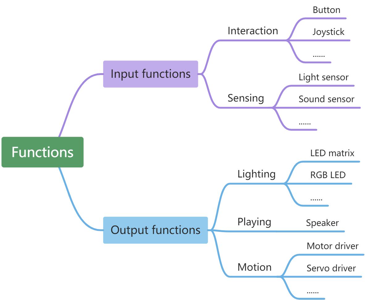
Structural characteristics
All mBuild modules are developed with two through-holes.
With the through-holes, mBuild modules can be mounted on each other with connectors, such as pins and screws. In addition, they can be connected to mechanical parts (M4), building blocks, and other structural parts through connectors. The following provides some connection examples:
Example 1: Speaker + one pin + servo driver
Example 2: Speaker + one pin + one cut board
Example 3: Speaker + one pin + one beam (M4)
Example 4: Speaker + one cut board + two screws + two brass studs
Electronic characteristics
mBuild ports
Most of the mBuild modules provide two mBuild ports.
With the mBuild ports, multiple mBuild modules can be connected in series.
In addition, the address of the modules can be intelligently identified when you program them on mBlock 5, which simplifies your programming. You don't have to set the information about the address of the modules when you add or remove a module.
Intelligent address identification
**Example: **
Connect CyberPi to multiple LED matrixes
After connecting CyberPi to multiple LED matrixes, you need only to specify the order of an LED matrix among the ones connected instead of specifying the port to which the LED matrix is connected when compiling a program. As shown in the preceding figure, the first LED matrix connected to CyberPi is numbered 1, the second one numbered 2, and so on.
When you press button A on CyberPi, the first LED matrix displays "Hello," and the second one displays "World."
Change the positions of the modules, as shown in the following figure.
The preceding program still works after you add a ranging sensor. When you press button A on CyberPi, the first LED matrix displays "Hello," and the second one displays "World."
Micro USB port
Some of the mBuild modules, such as Speaker, Power Module, and Smart Camera, provide a Micro USB port, which allows a module to directly connect to a computer for power supply or communication.
For details about how to get started with mBuild modules, see Getting Started.
Getting Started
Thank you for choosing mBuild modules!
If you use mBuild modules for the first time, read this page carefully and follow the instructions so that you won't miss their functions.
Before you use mBuild modules
Know about the wiring
Most of the mBuild modules provide two mBuild ports and therefore can be connected to main control boards or other mBuild modules through 4-pin cables. Some also provide a Micro USB port, which allows a module to directly connect to a computer for power supply or communication. For example, after connecting the speaker module to a computer, you can store audio files on it.
The following figure shows a 4-pin cable.
The following figure shows a connection example.
Provide power to mBuild modules
You can power mBuild modules in one of the following ways:
Way 1: use the power module
Connect the power module to the other modules through 4-pin cables. The power module is rechargeable. You can charge it by connecting it to a computer or charger.
Way 2: use a computer
Connect the mBuild modules to a main control board, such as Halocode or CyberPi, through 4-pin cables and then connect the main control board to a computer.
Start programming
With mBlock 5, you can program mBuild modules to implement their input or output functions. mBuild modules can be programmed as a device or as extension modules of a main control board.
Obtain mBlock 5
Select the version applicable to your device. For example, if you use a PC, you can download the version for PCs or use mBlock 5 on the web.
Block-based programming
Program mBuild modules as a device
In the following steps, mBlock 5 on the web is used.
-
Open the web version of mBlock 5 on your PC.
Choose File > New to start a new project.
-
Click + add on the Devices tab and add mBuild from the device library.
-
Connect the mBuild modules to mBlock 5 through the Bluetooth module.
:::info Note: To program mBuild modules as a device, you must connect them to mBlock 5 through the Bluetooth module. :::
(1) Connect the modules to be programmed in series and connect the Bluetooth module last.
(2) Turn on the power module, enable the Bluetooth function of your computer, and then place the module close to the computer until the indicator on the Bluetooth module keeps on.
Note: Currently, the mBlock 5 web version on Windows doesn't support the connection of the mBuild Bluetooth module to it through system Bluetooth. If your PC runs Windows or if it runs another system but the Bluetooth module can't be connected to mBlock 5 properly, you can use the mBlock 5 PC client (mBlock V5.2.0 recommended) or Makeblock Bluetooth dongle. For details about how to use Makeblock Bluetooth dongle, see the section "Connection through Makeblock Bluetooth dongle" in the mBlock 5 Online Help.
(3) Click Connect, choose Bluetooth in the dialog box that appears, and then click Connect.
A message is displayed after the mBuild modules are connected, indicating that the connection is successful.
Now, you can drag and drop blocks to the scripts area to compile your program!
Example programs
Example 1
When you press the space key, the speaker says "hello," and the LED matrix displays Hello.
Example 2
When you press the ↑ key, the two motor drivers provide power; and when you press the space key, they stop providing power.
:::tips Tips: After connecting the motor drivers to motors, you can control the motion of the motors through programming. :::
Program mBuild modules as extension modules of a main control board
In the following steps, Halocode is used as the main control board.
- Click + add on the Devices tab and add Halocode from the device library.
- Connect Halocode and the mBuild modules to your computer through a Micro USB cable.
- Click Connect and then click Connect in the dialog box that appears.
A message is displayed after Halocode is connected, indicating that the connection is successful.
- Add the Speaker and LED matrix extensions.
(1) Add the Speaker extension.
(2) Add the LED Matrix extension.
Now, you can drag and drop blocks to the scripts area to compile your program!
Block help
If you don't understand a block when using it, you can right-click it and click Help that appears to view its help information.
Python programming
You can also use MicroPython to program mBuild modules.
Set the programming language to Python.
For the Python API documentation of mBuild modules, see Python APIs for mBuild Modules.
:::tips Tips:
You can select mBuild modules and mount or install them on structures made of cut boards or mechanical parts as required. For example, you can install the motor driver modules on a car made of mechanical parts. :::
More information
For the functions and features of the mBuild modules, see Functions and Features.
Power
The power module powers other mBuild modules.
Indicators
| On | Off | |
|---|---|---|
| Green indicator | Power on | Power off |
| Red indicator | Low power/being charged | High power/charging completed |
Specifications
- Dimension: 48×48mm
- Battery capacity: 950mAh
- Battery voltage: 3.7V
- Discharge rate: 3CC
- Battery life: 3 hours ( reference only)
- Charging time: 1.25 hours
- Output voltage: DC 5V
- Discharge current: 5V 1.5A, with the maximum instantaneous value of 5V 2A
- Protection current: 5V 3A(You need to connect the Power module to a charger to restart it after the protection is triggered.)
- Input voltage: DC 5V
- Input current: <2A
- Working temperature :0℃–45℃
- Service life:≥ 300 battery cycles
Precautions
- Read the instructions carefully before using it
- Keep it Away from heat sources, high-voltage places and do not knock or hit it while using it
- Dispose of it properly and safely, and do not throw them into fire or water
- During use or storage, if the power module is hot, leaking, smelling unusual, deformed, or in any other abnormal state, stop using it immediately
Bluetooth
The Bluetooth module can work with Makeblock Bluetooth dongle or any device supporting Bluetooth 4.0, enabling you to control mBuild modules wirelessly.
For the settings for Bluetooth connection, see "Connection through Bluetooth 4.0."
LED Indicator
Specifications
- Dimensions: 24×24 (mm)
- Distance recommended: less than 10 m
- Bluetooth version: BT4.0
- Bandwidth: 2402–2480 (MHz)
- Antenna gain: 1.5 dBi
- Energy consumption level: ≤4 dBm
- Operating current: 15 mA
IR Transceiver
The IR transceiver module can transmit and receive infrared signals in the 940 nm band.
Real-life examples
-
Air conditioner and its remote control
-
TV set and its remote control
Specifications
- Dimensions: 24 × 24 (mm)
- Frequency band: 940 nm
- Supported protocol: NEC
- Transmission range: 6 m
- Receiving range: 6 m
- Operating current: 40 mA
Button
The button module can function as an event trigger, status switcher, or counter.
Real-life examples
- The power button is used to turn on or off the PC.
- The Home button of iPhone can be used to lock or unlock the screen.
- The buttons of a mouse can record the number of times they are pressed.
Specifications
- Dimensions: 24 × 20 (mm)
- Service life: 100 thousand
- Operating current: 15 mA
Joystick
The joystick module can be used to control the direction of a moving object. It can output the values of x- and y-coordinates to which it is pulled.
The following figure shows the ranges of the coordinates and how the directions are defined.
Real-life examples
-
A game controller uses joysticks to control a character's direction of movement or field of view.
-
A drone remote control uses joysticks to control the rotation direction and speed of the drone.
Specifications
- Dimensions: 24 × 36 (mm)
- Service life: 500 thousand
- Value range of the x-coordinate: –100 to +100
- Value range of the y-coordinate: -100 to +100
- Operating current: 15 mA
- Position reset precision: ±0.2 mm
Angle Sensor
The angle sensor is made of a magnetic encoder that can detect the position of rotation accurately. Unlike the knob, the angle sensor can rotate continuously, detecting the degrees of rotation and the angular velocity in real time. In addition, the angle sensor can work with a variety of plates to connect to various structural components and thus can be applied in different scenarios.
Working principle
In electromagnetism, if we apply a voltage to the two ends of a rectangular conductor, current is generated in one direction. When this happens, if we apply a magnetic field perpendicular to the conductor plane to the conductor as shown in the following figure, the Lorentz force is induced, leading to a path offset of the charges flowing through the conductor.
According to Fleming's left-hand rule, the direction of the offset can be determined, and the offset direction of the positive charges is opposite to that of the negative charges. Then, as shown in the preceding figure, the positive and negative charges flow through the intermediate conductor along two different paths on the left and right, respectively.
When this happens, an electric potential difference is generated between the sides of the conductor, that is, in a direction perpendicular to that in which the current flows. This is the Hall Effect.
According to the Hall Effect, we know that the current varies with the change of the magnetic field. Therefore, if the change of a magnetic field can be determined based on the change of current and thus the position change of a magnet can be determined, then the position or rotational speed of a shaft equipped with a magnet can be detected.
Real-life examples
- Some smart servos use magnetic encoders to detect angles.
- You can set the sound volume of your Apple Watch by turning its Digital Crown.
Specifications
- Dimensions: 24 × 36 (mm)
- Angle precision: ±1°
- Operating current: 22 mA
Multi-touch
The multi-touch module consists of multiple touch sensors, each of which can detect whether the corresponding touch point is being touched. When a touch point is touched, the LED indicator of the corresponding touch sensor is lit up.
You can also extend the touch points through alligator clips or wires, so that the multi-touch module can be applied in more scenarios. For example, you can use a piece of wire to connect a touch point to a fruit.
The multi-touch module can adjust the threshold values intelligently. Each time the system starts up, all the threshold values are reset. In addition, the sensitivity of the multi-touch module is programmable. For example, you can set the sensitivity to high to implement air touch.
Working principle
The multi-touch module applies the principle of capacity detection. There is an initial capacity (Cp) between a touch point and the ground. When a touch point is touched by you or another conductor, another capacity is formed. When this happens, the capacity between the touch point and the ground changes, and the MCU determines that the touch point is touched.
To sum up, the determination of touching depends on the detection of capacity change, and therefore, the MCU may detect touching when no touch point is touched.
Real-life examples
- Some robots are equipped with touch sensors on their backs to detect whether they are touched by users.
- Your cell phone screen is large and complex touch sensor.
Specifications
- Dimensions: 24 × 72 (mm)
- Operating current: 18 mA
Slider
The slider module can be used to control input.
Working principle
You can slide the slider on the slider module to change the resistance and thus change the voltage in the corresponding circuit. Based on the relation between the voltage and resistance, the resistance can be calculated and thus the position of the slider can be determined.
Real-life examples
- The sound volume of a cell phone is set through a slider.
- The progress of video playing is controlled through a slider.
Specifications
- Dimensions: 24 × 72 (mm)
- Service life: 15 thousand
- Output value range: 0–100
- Value precision: ±2%
- Operating current: 15 mA
Science Sensor
Overview
The science sensor is a multi-in-one sensor developed independently by Makeblock. Integrating the gas, magnetic field, flame, air pressure, temperature & humidity, PIR, touch, and soil moisture sensing components, the science sensor can be used in various data collecting, science exploring, and Internet of Things (IoT) projects.
Functions and parameters
| **Whole ** | Science sensor | Dimensions: 78.2 × 24 × 1.6 (mm) Operating voltage: 5.0 V Operating current: 250 mA | | | --- | --- | --- | --- | | Components | Name | Function | Parameter | | | MQ2 gas sensor | Sensitively detects smoke, liquefied natural gas (LNG), butane, propane, methane, alcohol, and hydrogen in the air. |
- Gas concentration detection range: 300–10000 ppm (flammable gas)
- Impedance when heated: 33Ω
- Preheating energy consumption:< 950 mW | | | | Note: The deviation may be large at the moment when the sensor is powered on. Heat it for five minutes before you use it. | | | | | | | | | Magnetic field sensor | Measures the angle between the x-aix of the magnetic field sensor and North Pole (90°N) after being calibrated. |
- Degree detection range: –180° to +180°(The angle 0° refers to 90°N.)
- Magnetic flux range:
±30G (unit: gauss) | | | | Note:
- Place the sensor on a horizontal plane before you use it. Tilting it may cause a large detection deviation.
- Ensure that no powerful magnetic material, such as a magnet, is placed nearby. Otherwise, detection errors may be caused. | | | | | | | | | Flame sensor | Detects a flame and its strength through IR light detection. |
- Detection wavelength range: 600–1000nm
- Flame strength range: 1–100 | | | | Note: Don't use the sensor under the direct sunlight. The sunlight may cause severe interference. | | | | | | | | | Air pressure sensor | Estimates the altitude based on the detected air pressure. |
- Air pressure detection range: 300–1100 hPa (unit: hundred pascals)
- Altitude value range: –500 m to +6000 m | | | | Note: Ensure that there are no particles, such as dust, on the surface of the sensor. Otherwise, the sensor may be damaged. | | | | | | | | | Humiture sensor | Detects the humidity and temperature of the air. |
- Temperature value range: –40°C to +125°C
- Temperature error:
- ±0.5°C (in the environment of 0°C to 50°C)
- ±1°C (in the environment of –20°C to +85°C)
- Humidity value range: 0–100%
- Humidity error:
- ±3% (in the environment of 50% RH)
- ±5% (in the environment of 20% to 80% RH) | | | | Note: Ensure that there are no particles, such as dust, on the surface of the sensor. Otherwise, the detection deviation may be large or the sensor may not work properly. | | | | | | | | | PIR sensor | Detects whether a human being or homeothermic animal passes by. |
- Detection range: < 2 m
- Detection angle at the x-axis: 80°
- Detection angle at the y-axis: 55°
- Detection duration after being triggered: 2 seconds | | | | Note: Don't remove the white Fresnel filter. Otherwise, a large detection deviation may be caused. | | | | | | | | | Touch sensor | Detects whether a hand touches the sensor. |
- Touch area: area with the fingerprint pattern
- Resistance value range: 0–102300000kΩ | | | | Note: Keep the area of the fingerprint pattern clear without any dust or waterdrop to prevent detection errors. | | | | | | | | | Soil moisture sensor | Detects soil moisture. |
- Detection range: probes
- Moisture value range: 0–100% (RH)
- Resistance value range: 0–102200kΩ | | | | Note: Ensure that the nameplate of the science sensor is kept above the soil when you insert the sensor into the soil. Otherwise, the other sensing components may be damaged. | |
Example programs
Example programs for the science sensor
Example 1: PIR-sensitive lamp (using the PIR sensor)
You can control the LEDs on CyberPi based on the PIR sensor and view the detection result of the PIR sensor on the screen. For the working principle of the PIR sensor, see the Working principle of the PIR sensor.
Example 2: Environment detector (using the humiture sensor and air pressure sensor)
The humiture sensor on the science sensor can be used to detect the ambient temperature and humidity, and the air pressure sensor can be used to detect the air pressure and estimate the altitude. You can program the screen of CyberPi to display all the output data of the sensors.
Example 3: Fire alarm (using the MQ2 gas sensor and flame sensor)
The science sensor integrates an MQ2 gas sensor and flame sensor, which can be used to detect gas leaks and fires in families.
With these two sensors, you can make a simple alarm that is to be triggered by a flammable gas or flame. When the alarm is triggered, CyberPi makes a warning sound.
For the working principle of the flame sensor, see the Working principle of the flame sensor. The flame sensor is triggered by infrared radiation, and the infrared radiated by a human body may also trigger it. Therefore, in pratice, you can set a threshold (strength of the flame detected) for triggering the flame sensor.
Example 4: Compass (using the magnetic field sensor)
The magnetic field sensor on the science sensor can be used to function as a compass. The magnetic declination varies according to region, and therefore you need to calibrate the magnetic field sensor before using it.
:::info
Note: You need to calibrate the magnetic field sensor in a non-magnetic environment. An outdoor open space is recommended.
:::
Use the following block to enable or disable the calibration.
Output value range: –180° to +180°(where 0° indicates that the science sensor points at 90°N, the North Pole)
Program the science sensor to function as a compass.
Example 5: Soil moisture detector (using the soil moisture sensor)
The soil moisture sensor on the science sensor is of the resistive type. When the soil moisture increases, the water can dissolve the ions contained in part of the soil, so that the resistance of the soil decreases, and therefore the output value of the soil moisture sensor becomes greater. When the water content in the soil further increases (in the case of extremes, imagine that you throw some soil into water), the ion concentration in the soil is diluted by excess water, resulting in a decrease in electrical conductivity and an increase in resistance. That's why you may find that the soil moisture sensor outputs a smaller value in pure water than in moist soil (although the former has a significantly higher water content) because the ion concentration in the moist soil is higher and the resistance is smaller.
With the following program, you can view the change in soil moisture and resistance detected by the soil moisture sensor.
Example 6: Touch control lamp (using the touch sensor)
The touch sensor on the science sensor can detect whether the touch point is touched and thus can implement touch-based control.
With the following program, you can control the LEDs on CyberPi by touching the touch sensor.
Quad RGB Sensor
The quad RGB sensor uses visible light as fill lights, which significantly reduce the interference of ambient light. In addition, it provides the function for recognizing colors. The new ambient light calibration function also reduces the interference of the ambient light in line following. With four light sensors, it can support more programming scenarios.
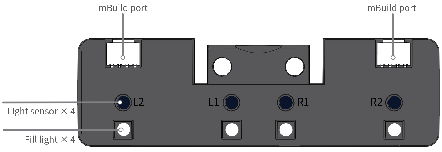
| Quad RGB sensor | Dual RGB color sensor | |
|---|---|---|
| Plastic casing to improve the durability and quality | Yes | No |
| Line-following sensor | 4 | 2 |
| Color sensor | 4 | |
| (also serve as line-following sensors) | No | |
| Light sensor | 4 | |
| (also serve as line-following sensors) | No | |
| Fill light | Visible light | IR light |
| Ambient light calibration to significantly reduce the interference of ambient light | Yes | No |
Specification
Detection range: 5–15 mm from the object to be detected
Button description
- Double-press: When the button is double-pressed, the quad RGB sensor starts to learn the background and line for line following.
Place the light sensors on the background of the line-following track map and double-press the button. When you see the LEDs indicating the line-following state blink quickly, sway the sensors from side to side above the background and line until the LEDs stop blinking. It takes about 2.5 seconds. The parameter values obtained are automatically stored. If the learning fails, the LEDs blink slowly, and you need to start the learning again.
- Long-press: When the button is long-pressed, the quad RGB sensor switches the color of the fill lights. Generally, you don't need to change the color. The color is set automatically after the learning is complete.
Programming guide
You can use mBlock 5 to program the quad RGB sensor. Connect the quad RGB sensor to CyberPi, add CyberPi and connect it to mBlock 5, and then add the Quad RGB Sensor extension. For details about how to add CyberPi and connect it to mBlock 5 and how to add the extension, see "Add and connect mBot2" and "Add extensions."
Set the detection mode
The quad RGB sensor can be programmed to detect either of the following:
- color
- grayscale
For color detection, the quad RGB sensor measures the light reflected by an object in terms of its Red, Green, and Blue (RGB) values. Eight colors are available.
To detect a color, you need to select a color in the block to be used, for example:
For grayscale detection, the quad RGB sensor measures the intensity of the light reflected by an object regardless of its color.
To detect grayscale, you need to select line or background in the block to be used, for example:
Obtain the output values
The quad RGB sensor can output values based on the color or grayscale it detects, and you can obtain these values by using the reporter blocks, for example:
Change the color of the fill lights
You can change the color of the fill lights between green, red, and blue by long-pressing the button or by using the following block:
:::info Note: The quad RGB sensor can detect colors regardless of what colors the fill lights are. :::
You need to change the color of the fill lights in some application scenarios. For details, see "Line detection scenarios."
Line detection scenarios
Before you use the quad RGB sensor to detect lines, you need to perform basic calibration on it.
Basic calibration
- Place the four light sensors of the quad RGB sensor on the background and double-press the button on the sensor, and then sway the sensor horizontally over the line and background.
- Check the two light sensors in the middle (L1 and R1) of the quad RGB sensor. If the robot is on the line, the blue LEDs of the two light sensors are supposed to be off. The two LEDs are turned on and off alternately when you sway the robot over the line. :::tips Tips: The quad RGB sensor can detect dark lines on light backgrounds regardless of the color of the illumination. :::
The following describes multiple line detection scenarios, and the purposes and blocks recommended for each scenario.
Scenario 1: Black line + white margin around line + white background
For example:
Perform basic calibration on the quad RGB sensor, so that it can recognize the line and background.
| Level | Purpose(s) and block(s) recommended | Remarks |
|---|---|---|
| 1a: junior |
- To determine whether the quad RGB sensor detects the specific line status:
- To obtain the status of the line detected
|
|
| 1b: intermediate |
To detect crossings
| The quad RGB sensor can't overlook the line, and therefore it can't determine whether a T-junction is actually a crossing ("+" shape, the actual line continues after the T). This can only be checked by driving straight over the T and detecting if the line continues. |
| 1c: advanced | To implement smooth line following:
| Check the output value of this block.
Switch the color of the fill lights to make sure that the output value is 0 when the robot is in the middle of the line.
The color of the fill light may have a slight impact on the output value. |
Scenario 2: Black line with colored sections + white margin around line + white background
For example:
The purposes and blocks recommended are the same as those in Scenario 1, but special calibration is required.
Either of the following ways can be used:
-
Perform the basic calibration on the lightest color among the colored sections, for example, yellow, so that all darker colors are recognized as black.
-
Perform basic calibration on the black line, and then long-press the button on the sensor to change the color of the fill light and see if the sensor recognizes the different colored sections as the line to be followed.
- red section: use the green or blue/white fill light
- yellow section: use the blue/white fill light
- green & blue section: all fill lights work :::warning Important to know:
-
If you have set the color of the fill lights on mBlock 5, the calibration resets the fill lights (each fill light cycles through R/G/B illumination fast).
-
Colored sections inside the line to be followed may affect the advanced, smooth line following (recognized as the deviation from the line). For example, when the basic calibration is done on the yellow section, the blue section may be reported as a deviation even if it is 100% on the line. :::
Scenario 3: Single-colored line + white margin around line + white background
For example:
Perform basic calibration on the quad RGB sensor, so that it can recognize the line and background.
The purposes and blocks recommended are the same as those in Scenario 1.
:::info
**Notes: **
- If you use the deviation reporter block, long-press the button on the quad RGB sensor to switch the color of the fill lights to make sure that the output value is 0 when you put the robot in the middle of the line.
- It is not recommended to use the deviation reporter block when the contrast between the line and background is low. :::
Scenario 4: Black line + white margin around line + colored background/illustrations
For example:
Perform basic calibration on the quad RGB sensor, so that it can recognize the line and background.
| Level | Purpose(s) and block(s) recommended | Remarks |
|---|---|---|
| 4a: junior |
- To determine whether the quad RGB sensor detects the specific line status:
- To obtain the status of the line detected
|
|
| 4b: intermediate |
To detect crossings:
| The outer areas (background) may be recognized as the line to be followed, depending on the light conditions.
When this happens, you can use only the L1 and R1 light sensors to detect lines, or make sure that the white margin around line is wide enough to keep the sensors from detecting the outer background. |
| 4c: advanced | To detect deviation from the line:
| If the colors of the outer areas are close enough to the color of the line to be followed, the output value of the deviation reporter block may be affected, and thus line following may fail.
In this case, long-press the button on the quad RGB sensor to change the color of the fill lights, making sure that the difference between the line and background is recognized. The blue LEDs are turned on and off alternately when you sway the sensor over the line.
If you use the deviation reporter block, switch the color of the fill lights to make sure that the output value is 0 when the robot is put in the middle of the line. The color of the fill light may have a large impact on the output value. |
Scenario 5: Black line + single-colored margin around line + white background
For example:
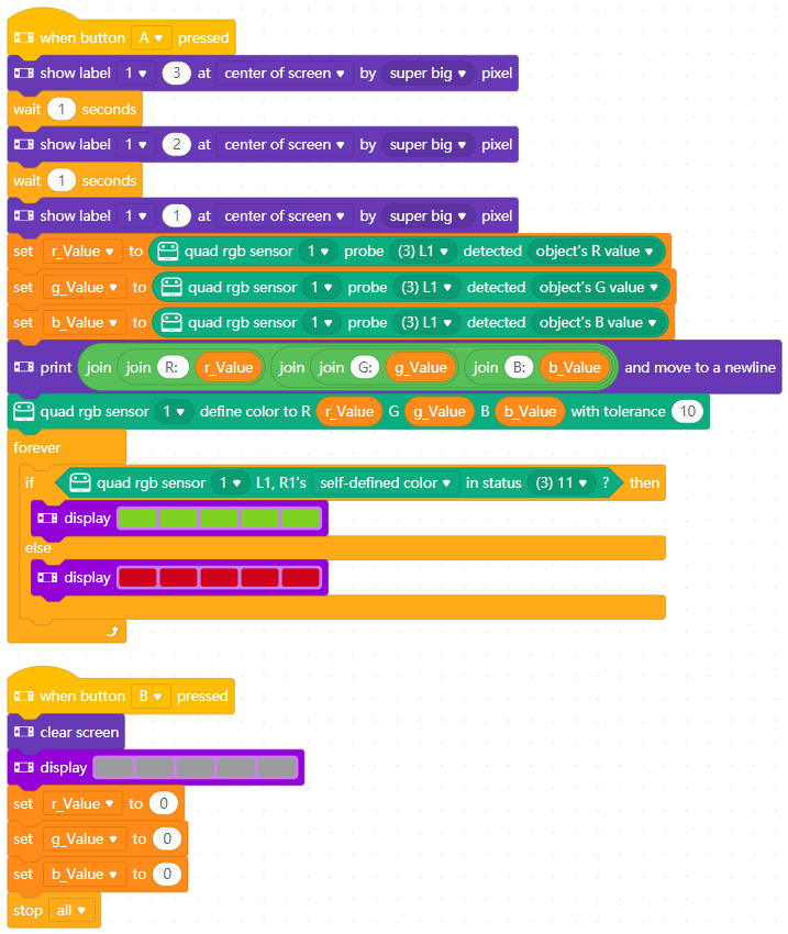 Perform basic calibration on the quad RGB sensor, so that it can recognize the line and background.
The purposes and blocks recommended are the same as those in 1a of Scenario 1. Crossing detection and deviation detection are not recommended because the margin around lines may be recognized by L2 or R2 as the line to be followed.
:::tips
Tips: You can also program the quad RGB sensor to detect light-colored lines on dark or colored backgrounds.
:::
Perform basic calibration on the quad RGB sensor, so that it can recognize the line and background.
The purposes and blocks recommended are the same as those in 1a of Scenario 1. Crossing detection and deviation detection are not recommended because the margin around lines may be recognized by L2 or R2 as the line to be followed.
:::tips
Tips: You can also program the quad RGB sensor to detect light-colored lines on dark or colored backgrounds.
:::
Color detection programming examples
Example 1: Obtain the values of RGB detected by light sensors of the quad RGB sensor
Use the following program to display the values of RGB detected by the light sensors of the quad RGB sensor on the screen of CyberPi:
RGB output

Example 2: Define a color and its tolerance
- You can define a color with the following RGB ranges:
- R: 0–255
- G: 0–255
- B: 0–255
- Tolerance
For example, set the block as follows.
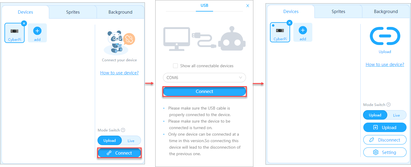
| | R | G | B | | --- | --- | --- | --- | | Initial RGB values | 255 | 40 | 40 | | If tolerance is set to 10, then: | | | | | Upper limit of RGB values | 255 | 50 | 50 | | Lower limit of RGB values | 245 | 30 | 30 |
You can set the tolerance based on the ambient light and object color differences.
Example program:
Define a color
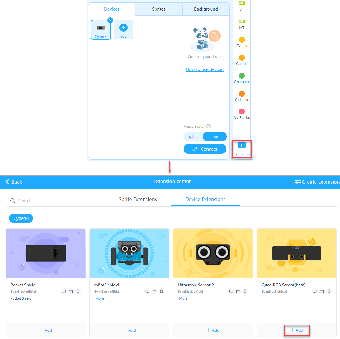 After you start CyberPi, the LEDs on CyberPi light up in green when the color defined by you, red in this example, is detected by both sensors R1 and L1. Otherwise, the LEDs on CyberPi are on in red.
Example 3: Tell the color of an object
Example program:
Tell the color of an object
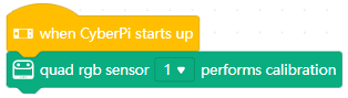 (1) Place the quad RGB sensor over the object of which the color is to be recognized.
(2) Press button A on CyberPi. The color of the object is detected and the RGB values are displayed on the screen of CyberPi.
(3) Press button B on CyberPi. The RGB values are cleared from the screen on CyberPi.
(1) Place the quad RGB sensor over the object of which the color is to be recognized.
(2) Press button A on CyberPi. The color of the object is detected and the RGB values are displayed on the screen of CyberPi.
(3) Press button B on CyberPi. The RGB values are cleared from the screen on CyberPi.
Block added for quad RGB sensor calibration
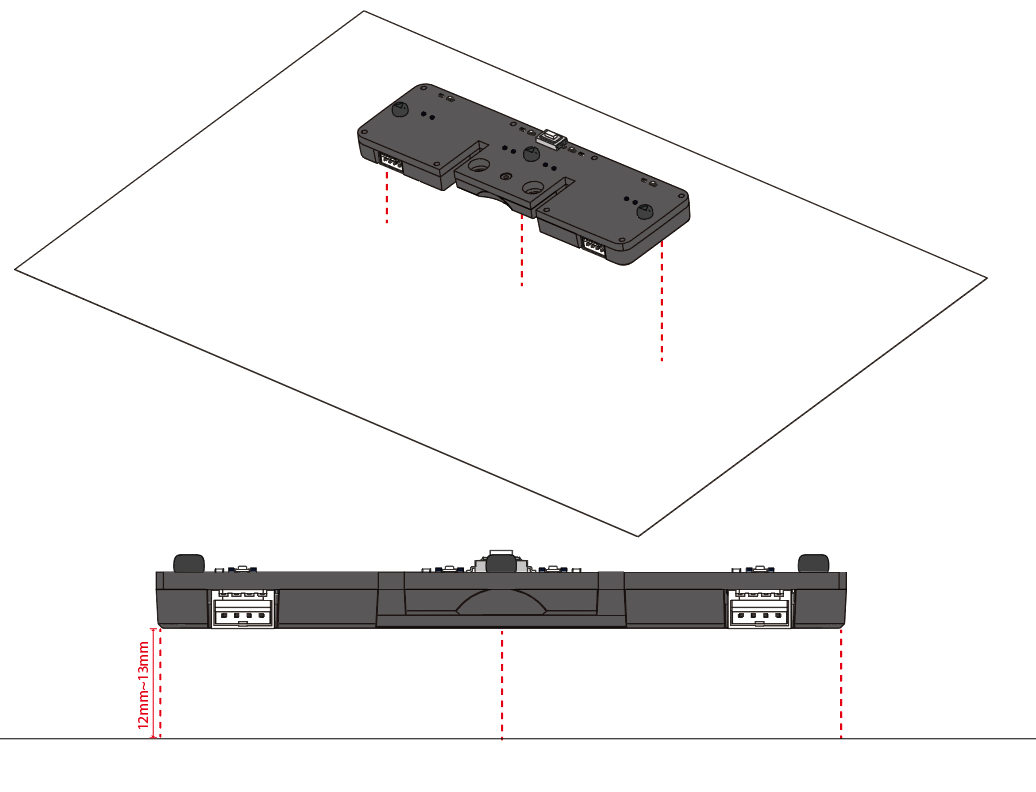
Why do I need to perform calibration on the quad RGB sensor?
The performance of the quad RGB sensor may be significantly affected by the ambient light, map, color card, or the distance between the light sensors and the object to be detected. Therefore, performing calibration on the quad RGB sensor in the environment and conditions where it is to be used can improve the detection accuracy.
Calibration preparation
- Update the firmware to version 011, and update the Quad RGB Sensor extension to the latest version.
- Assembled mBot2, or CyberPi + mBot2 Shield + quad RGB sensor
- White paper of A6 or larger, or the white area on the mBot2 line-following map
- Find a place with common room light instead of intense light
Calibration steps
(1) Connect the quad RGB sensor to the mBuild port on mBot2 Shield or CyberPi by using an mBuild cable.
(2) Connect CyberPi to your computer by using a USB cable.
(3) Open mBlock 5 and connect CyberPi to mBlock 5.
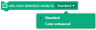 (4) Add the Quad RBG Sensor extension.
(5) Write the following program and upload it to CyberPi. Alternatively, you can write a program in Live mode.
The calibration process is short. Place the quad RGB sensor (12 mm to 13 mm recommended) over the white paper before you start the calibration program.
During the calibration, the fill lights are lit up in other colors and then reset to the pre-defined color, which looks like blinking. When the calibration is complete, it says "Calibration completed" on the screen of CyberPi. You can execute the program to perform calibration on the quad RGB sensor again.
Block added for switching color detection mode
What does the color detection mode mean?
The algorithm of the quad RGB sensor is performed based on the hue, saturation, value** (**HSV) color model. The standard mode refers to the threshold used in earlier firmware versions, and the color enhanced mode is added to the latest firmware, in which the threshold is adapted to application scenarios based on the HSV model. You can select a color detection mode as required.
Notes
By default, the standard color detection mode is used when this block is not executed. To switch back to the standard mode after you have used the color enhanced mode, you can use either of the following two ways:
- Delete the sets color detection mode to () block from your program. But note that you need to power off CyberPi and restart it to make the standard mode take effect.
- Use the sets color detection mode to () block and select the Standard mode.
Ultrasonic Sensor 2
The ultrasonic sensor 2 can be used to detect the distance between an obstacle and it. The transmitter on the left transmits ultrasonic waves, and the receiver on the right receives the ultrasonic waves reflected.
Compared to the ultrasonic sensor we've developed before, the ultrasonic sensor 2 is improved in its casing, chip, and blue LEDs. The blue LEDs can increase the potential for emotion expression and interaction.
Ultrasonic sensor comparison
Ultrasonic sensor 2
Ultrasonic sensor
| | --- | --- | --- | | Plastic casing to improve the durability and quality | Yes | No | | Built-in chip to improve the operation stability | Yes | No | | Blue LED (additional function) | 8 | 0 |
Specifications
- Output range: 5–300 cm (The output value is 300 when the distance detected is out of the output range.)
- Output value error: ±5%
Working principle
Human beings can hear sounds of 20 to 20,000 Hz. Sound waves with frequencies higher than 20,000 Hz are called ultrasonic waves. The sound waves are reflected back by the obstacles they encounter and are received by the receiver of the ultrasonic sensor. Based on the time between transmission and receiving, the distances between the ultrasonic sensor and the obstacles can be calculated.
Real-life example
- Bats locate objects with ultrasonic waves.
Programming guide
You can use mBlock 5 to program the ultrasonic sensor 2. Connect the ultrasonic sensor 2 to CyberPi, add CyberPi and connect it to mBlock 5, and then add the Ultrasonic Sensor 2 extension. For details about how to add CyberPi and connect it to mBlock 5 and how to add the extension, see "Add and connect mBot2" and "Add extensions."
Distance detection and determination
To obtain the distance between the obstacle and the ultrasonic sensor 2, use:
To determine whether an obstacle is found within the output range of 5 cm to 300 cm, use:
Generally, the distance detection and determination functions are used to implement obstacle avoidance.
For example:
When no obstacle is within the detection range of the ultrasonic sensor 2, mBot2 moves forward at the speed of 100 RPM; when an obstacle is detected, it moves forward at the speed of 50 RPM; and when the distance between the obstacle and it is shorter than 20 cm, it turns left.
Emotion and information expression
The ultrasonic sensor 2 is equipped with eight blue LEDs. Through programming their brightness, you can use the ultrasonic sensor 2 to express various types of emotions and information.

Example 1:
After you press button A, the ultrasonic sensor 2 expresses the emotion of happiness by "smiling" when you shake it.
:::info
Note: In this example, "smiling" is performed by lighting up the blue LEDs in positions 1, 2, 5, and 6 and turning off those in positions 3, 4, 7, and 8.
:::
Alternatively, you can use the emotion block provided on mBlock 5 to express an emotion:
Example 2:
After you press button A, place an obstacle close to the ultrasonic sensor 2, and then move the obstacle slowly away from it.
You can see that the blue LEDs become brighter as you move the obstacle. A higher brightness indicates a larger distance.
MQ2 Gas Sensor
The MQ2 gas sensor can easily detect smoke, liquefied natural gas (LNG), butane, propane, methane, alcohol, and hydrogen in the air.
Working principle
The MQ-2 type smoke sensor is made of a tin dioxide semiconductor gas sensing material. When it works at a temperature of 200 to 300 °C, the tin dioxide adsorbs the oxygen in the air, which reduces the density of electrons on the semiconductor and thus increasing the resistance. When it comes into contact with smoke, if the barriers at grain boundaries are changed by the smoke, the conductivity on the surface is changed accordingly. In this way, smoke can be detected. A higher smoke density indicates a higher conductivity and lower output resistance.
Real-life example
- A smoke alarm can detect smoke and flammable gas.
Specifications
- Dimensions: 24 × 36 (mm)
- Operating current: 160 mA
- Impedance when heated: 33Ω
- Preheating energy consumption:< 800 mW
Note
The detection error may be large when the module starts to work. The module can be preheated for five minutes for better performance.
Magnetic Sensor
The magnetic sensor detects whether there is a magnet around.
Real-life example
A sweeping robot uses the magnetic field detection function in its virtual wall to determine whether it can go through.
Specifications
- Dimensions: 24 × 20 (mm)
- Detection distance: <1 cm
- Operating current: 15 mA
Humiture Sensor
The humiture sensor can detect the temperature and humidity in the surrounding area. You can use it to make a smart fan, smart humidifier, and so on.
Real-life example
- Smarthome devices use a humiture sensor to detect the temperature and humidity and thus adjusting the indoor environmental conditions.
Specifications
- Dimensions: 24 × 20 (mm)
- Temperature range: –40 to +125 (℃)
- Temperature error: ±1℃
- Humidity range: 0–100%
- Humidity error: ±3%
- Operating current: 15 mA
Temperature Sensor
The temperature sensor can detect the temperature of the object that comes into contact with its probe.
Before you use the temperature sensor, connect it to the probe delivered with it, as shown in the preceding figure.
Real-life example
- An electronic thermometer uses a temperature sensor.
Specifications
- Dimensions: 24 × 20 (mm)
- Value range: –55 to +125 (℃)
- Value error: ±0.5℃
- Operating current: 14 mA
PIR Sensor
The passive infrared sensor (PIR sensor) can detect whether a human being or homeothermic animal passes by.
Working principle
The PIR sensor uses a human pyroelectric infrared sensor as a core component. The normal temperature of a human body is 37 °C, corresponding to the infrared light of 10 μm in wavelength. The PIR sensor detects the movement of a human body or heat source nearby by detecting the change of the infrared light of 10 μm in wavelength.
To sensitively detect the change of the 10 μm infrared light, the PIR sensor uses a Fresnel filter to concentrate the infrared light so that the sensor can receive as much infrared light as possible in the environment.
Real-life example
- A shopping mall uses a PIR sensor on its automatic door to determine whether to open or close the door.
Specifications
- Dimensions: 24 × 20 (mm)
- Detection range: 3–5 (m)
- Detection angle range at the x-axis: 80 degrees
- Detection angle range at the y-axis: 55 degrees
- Operating duration after being triggered: 3s
- Operating current: 15 mA
Motion Sensor
The motion sensor consists of a 3-axis gyroscope and 3-axis accelerometer and can detect the motion, acceleration, and vibration of an object.
Axes and angles
| Axis | Angle name | Angle range |
|---|---|---|
| X | Pitch | –180° to +180° |
| Y | Roll | –90° to +90° |
| Z | Yaw | –180° to +180° |
Working principle
If you search for gyroscopes on the Internet, the following figure is most likely to be found.
This is a theory based on the conservation of angular momentum. A gyroscope is a mechanism used to sense and maintain directions. It is mainly composed of a rotatable rotor that is located at the axis. Due to the angular momentum of the rotor, once the gyroscope begins to rotate, there is a tendency to resist the change of direction. Such gyroscopes are used in early navigation systems.
In modern electronic products, thanks to the thriving of the microelectromechanical technology and due to the limitation of volume, microelectromechanical systems (MEMS)-based gyroscopes are widely used. It is small in volume and can be directly soldered to a PCB. That's why we can produce a motion sensor with the dimensions of 24 × 20, in millimeters.
The working principles of these two types of gyroscopes are quite different, but what you need to know is that they can more realistically reflect the posture and motion state of an object in space.
Real-life example
- The gyroscope used in Nintendo Switch enables you to play somatosensory games.
- iPhone uses a gyroscope to implement its Level function.
Specifications
- Dimensions: 24 × 20 (mm)
- Angle precision:±1 (degree)
- Acceleration detection range: ±8g
- Operating current: 18 mA
Flame Sensor
The flame sensor can sense a flame and its size through detecting IR light.
Sunlight contains a large amount of infrared light, which may severely interfere with the operation of the flame sensor, and therefore the flame sensor can't work properly when placed in direct sunlight.
Real-life example
- Flame sensors can be a great help in places where fire is strictly prohibited.
Specifications
- Dimensions: 24 × 20 (mm)
- Value range: 0–100
- Consistency error:
- Operating current: 20 mA
Ranging Sensor
The ranging sensor can sense the distance between an obstacle and itself through detecting infrared waves.
Real-life example
- iPhone uses infrared wave detection to obtain facial structures and store them as biometric data to implement the Face ID function.
Specifications
- Dimensions: 24 × 20 (mm)
- Value range: 2–200 (cm)
- Value precision: ±5%
- Operating current: 33mA
Ultrasonic Sensor
The ultrasonic sensor can be used to detect the distance between an obstacle and it. The left probe of the ultrasonic sensor transmits ultrasonic waves and the right one receives ultrasonic waves.
Working principle
Human beings can hear sounds of 20 to 20,000 Hz. Sound waves with frequencies higher than 20,000 Hz are called ultrasonic waves. The sound waves rebound from the obstacles they encounter and are received by the probe of the ultrasonic sensor. Based on the time between transmission and receiving, the distance between the ultrasonic sensor probe and the obstacle can be calculated.
Real-life example
- Bats locate objects with ultrasonic waves.
Specifications
- Value range: 5–300 (cm) (The value 300 is reported when the value exceeds the range.)
- Value error: ±5%
- Operating current: 26 mA
Sound Sensor
The sound sensor can detect the volume of the sound in the ambient environment.
Real-life example
Specifications
- Dimensions: 24 × 20 (mm)
- Value range: 0–100
- Consistency error: ±5
- Operating current: 40 mA
- Microphone sensitivity: –45 to +39 (dB)
- Microphone impedance: 2.2 kΩ
- Microphone S/N ratio: 55 dB
Dual RGB Color Sensor
The dual RGB color sensor consists of a pair of light-sensitive elements to detect the color of an object. It can facilitate the line-following of robots while detecting colors.
The dual RGB color sensor can provide multiple types of data, including the analog output that indicates light intensity, the digital output that indicates the line and background states, and calculated parameter values for motor control, which ensures sufficient flexibility while simplifying your application process. Based on the data output, teachers can explain the knowledge and working principles from different aspects.
The dual RGB color sensor provides the adaptive map learning function. It automatically sets the thresholds after learning the colors of the background and to-be-followed line. The firmware of the sensor includes a line-following algorithm and can directly output parameter values for controlling the rotational speed of motors, which makes high-speed line following easier.
Button description
-
Press: No function is defined.
-
Double-press: When the button is double-pressed, the dual RGB color sensor starts to learn the background and line for line following.
Place the light sensors on the background of the line-following track map and double-press the button. When you see the LEDs indicating the line-following state blink quickly, sway the sensors from side to side above the background and line until the LEDs stop blinking. It takes about 2.5 seconds. The parameter values obtained are automatically stored. If the learning fails, the LEDs blink slowly, and you need to start the learning again.
- Long-press: When the button is long-pressed for two to three seconds, the dual RGB color sensor switches the color of the fill lights in the order of red, green, and blue. Generally, you don't need to change the color. The color is set automatically after the learning is complete.
Working principle
Each group of color sensors consists of a light sensor and RGB LED. In the real world, when you see an object in red, it indicates that the object absorbs more of the other light than the red light. Therefore, if you use a fill light to shine red light on an object, the redder the object is, the more light it reflects, and the greater the output value of the light sensor is. In this way, you can obtain the red intensity of the object. Similarly, you can change the color of the fill lights to obtain the green and blue intensity of the object and thus determine the color of the object.
Environmental interference and detection errors
In the physical world, you may find environmental interference and detection errors almost everywhere. If a color sensor needs to determine the color of an object based on the intensity of the light (shone by a fill light and reflected by the object) it detects, detection errors may be caused because the ambient light is also detected.
Pay attention to the detection errors. When you use two dual RGB color sensors to detect the color of an object in the same environment, the detection results may be different. But in general, the difference is small.
In practice, engineers use algorithms or some special design to avoid environmental interference and detection errors. For example, you can use a 3D printout to block the ambient light from reaching the object to be detected and the dual RGB color sensor; alternatively, you can use an algorithm: to record the ambient light intensity when the fill lights are turned off, and immediately record the intensity when the fill lights are turned on; and then calculate the difference between these two intensity values. This difference can be determined as the intensity of filling light reflected by the object. In the algorithm, the ambient light intensity is considered almost unchanged in a very short time.
For detection errors, you can also use an algorithm to classify multiple close values as one color.
Real-life example
- Color sensors are used to design an assembly line for parts sorting.
Specifications
- Detection range: 5–15 (mm) from the object to be detected
- Operating current: 70 mA
Light Sensor
The light sensor can detect the intensity of the ambient light.
Working principle
The mBuild light sensor uses a photoresistor as the core component that can change the resistance according to the light intensity. The change of the resistance can be detected by the MCU, and therefore the MCU can determine the light intensity in the environment.
Real-life examples
- A light sensor can be used to facilitate the brightness adjustment of a cell phone screen.
- Light sensors are used in some smart lamps to facilitate brightness adjustment based on the ambient light intensity detected.
Specifications
- Dimensions: 24 × 20 (mm)
- Value range: 0–100%
- Operating current: 15 mA
Soil Moisture Sensor
The soil moisture sensor can detect the level of moisture in the soil.
Working principle
There are two common types of soil moisture sensors, the capacitive ones and resistive ones. A capacitive soil moisture sensor measures the change in capacitance caused by soil moisture to estimate the humidity of the soil. A resistive one estimates the soil moisture based on the resistance detected between the two contacts.
The strict definition of soil moisture is the percentage of the water in the soil. Neither the resistive nor the capacitive soil moisture sensor can accurately predict the water content in the soil. They can only report humidity values that are positively correlated to the water content.
The mBuild soil moisture sensor is a resistive one. When the soil moisture increases, the water can dissolve the ions contained in part of the soil, so that the resistance of the soil decreases, and therefore the output value of the soil moisture sensor becomes greater. When the water content in the soil further increases (in the case of extremes, imagine that you throw some soil into water), the ion concentration in the soil is diluted by excess water, resulting in a decrease in electrical conductivity and an increase in resistance. Therefore, you may find that the soil moisture sensor outputs a smaller value in pure water than in moist soil (although the former has a significantly higher water content) because the ion concentration in the moist soil is higher and the resistance is smaller.
:::tips Remarks: The mBuild soil moisture sensor is a resistive one, and therefore it can also be used, to some extend, to detect resistance. We are considering developing some related ports. :::
Specifications
- Dimensions: 24 × 72 (mm)
- Value range: 0–100
- Consistency error: ±5%
- Operating current: 14 mA
Smart Camera
The smart camera can learn and recognize brightly colored objects as well as detecting bar codes and lines, which allows it to be used in various application scenarios, such as garbage sorting, intelligent transportation, object tracking, and intelligent line following.
Connect to mBot or Halocode
Based on the wiring mode, the smart camera can be used as an RJ25 electronic module or mBuild electronic. After connecting it to mBot or Halocode, you can control it through mBot or Halocode.
Connect to mBot
After connecting the smart camera to mBot, you can power it with a 3.7V lithium battery or the mBuild power module.
Method 1 Power through the mBuild power module (recommended)
Method 2 Power through a 3.7V lithium battery
Connect to Halocode
Note: It is recommended to power the smart camera through the mBuild power module. Power only through the USB port may affect the proper use of the block.
Features
Color learning
The smart camera can learn brightly colored objects and identify the color blocks after learning, and then return their coordinates, length, and width. Learn a colored object as follows:
- Long press the Learn button until the indicator turns red (orange, yellow, green, blue, or purple, different colors indicate learning different objects), and then release the button.
- Place the color block to be learned in front of the camera.
- Observe the indicator on the front or back of the smart camera, and slowly move the object to be learned until the color of the indicator matches the object.
- Short press the Learn button to record the current learned object. After the learning is successful, when the camera recognizes a learned object, the color of the indicator becomes the same as that of the learned object.
A maximum of seven objects can be learned and recorded in this mode.
| Action | Description |
|---|---|
| Long-pressing until the red light is on | Starts to learn color 1 |
| Long-pressing until the orange light is on | Starts to learn color 2 |
| Long-pressing until the yellow light is on | Starts to learn color 3 |
| Long-pressing until the green light is on | Starts to learn color 4 |
| Long-pressing until the cyan light is on | Starts to learn color 5 |
| Long-pressing until the blue light is on | Starts to learn color 6 |
| Long-pressing until the purple light is on | Starts to learn color 7 |
After the learning is complete, you can use the following program to track the color block (color block 1).
Note
- The brighter the color of the learned object, the more accurate the recognition.
Cautionary Example:learning a panda doll
- The smart camera can learn and record seven objects, which should be easily distinguished in color.
Cautionary Example:learning a yellow ball and a yellow hat
Good example:learning an orange ball and a green ball
- Switch the smart camera to the color block detection mode to detect the coordinates and size of the color block.
- The smart camera can prevent light interference. However, changeable light can still affect recognition accuracy. The previous learning results may fail to be used in a new environment. Here are some solutions:
- Reset the white balance
- Turn on the LED before learning or recognizing
- Set the detail parameters in PixyMon
- Use a lampshade to cover the blocks
Bar codes and lines recognizing
The smart camera can detect bar codes, lines, and branch roads simultaneously without learning.
Switch the smart camera to the line/label tracking mode to detect and return the coordinate information of bar codes, lines, and branch roads.
Bar codes recognizing
Bar code cards and stickers are included in the package. Click to download the bar code cards.
You can put the cards on the line-follower map.
Lines and branch roads recognizing
The smart camera can detect the lines and the number of branch roads, and return the coordinates, directions, and the number of branch roads.
Note
- You can set the line tracking mode to dark line on light or light line on dark in the program.
- The smart camera will filter out the narrow lines by default. Check PixyMon's user guide to change the default settings.
PixyMon
The smart camera supports PixyMon software. You can use PixyMon to view the camera screen, adjust smart camera functions, and fine-tune some parameters to explore more complex features. Follow the steps below to install and use PixyMon:
- Click the following links to download PixyMon. Download PixyMon for Windows Download PixyMon for Mac
- Double-click the installation package and follow the prompts to install it.
- After the installation is completed, open PixyMon.
- Connect Smart Camera to the computer via a USB cable.
- After you see the status bar showing connected as shown below, you can start exploring Smart Camara with PixyMon.
Note: For the ease of use of the module, we haven't developed many functions on the blocks. If you are interested in controlling the smart camera through the blocks to implement more features, use the mBlock 5 Extension Builder.
mBlock Extension Builder documentation
Parameters
- Dimensions: 48 × 48 (mm)
- Resolution: 640 x 480
- Field of view: 65.0 degrees
- Effective focal length: 4.65±5% mm
- Recognition speed: 60fps
- Recognition distance: 0.25–1.2 (m)
- Fall resistance: 1m
- Power supply: 3.7V lithium battery or 5V mBuild power module
- Power consumption range: 0.9–1.3W
- Operating temperature: -10℃–55℃
Example programs
Example 1: Color block tracking 1 – color block position tracking
In this example, mBot moves by tracking the specified color block. The motors rotate based on the position of the color block in the image captured by the smart camera. They stop rotating when the color block is detected in the center of the image or no color block is detected.
Note that the way you install the smart camera affects the tracking of the color block and thus affects the movement of mBot. The following figure shows an example of how the smart camera can be installed.
Program details
Example 2: Color block tracking 2 – color block coordinate tracking
In this example, the position (defined as A) of the color block in the image captured is obtained, and the target position is defined as B. Motors rotate based on the difference between A and B, where the difference is calculated based on the coordinates of A and B. In this way, more accurate tracking is performed. The way mBot moves by tracking color block coordinates is similar to that it moves by tracking color block positions.
Program details
Example 3: Line following
The smart camera can recognize line segments. Motors rotate based on the differential speed calculated based on the deviation of the line segment from the center of the image captured.
In line-following mode, it's recommended that you install the smart camera parallel to the line segment to be recognized.
Program details
**Note: **
- **Kp: **Sensitivity in making a turn. When the initial speed is higher or the turn is sharper, a greater Kp is required.
- **target: **initial speed
- offset: deviation from the lien to be followed. A positive value indicates a deviation to the left of the line, and a negative value indicates one to the right of the line.
8×16 Blue LED Matrix
The 8×16 Blue LED matrix can display animation, emojis, texts, or numbers. Each point on the matrix contains a LED, which can be controlled individually.
Real-life example
- Flight information displays used in airports are huge LED matrixes.
Specifications
- Dimensions: 64 × 44 (mm)
- Operating current: 150 mA
RGB LED
The RGB LED is programmable. You can light it up in different colors and set its brightness through programming.
Real-life examples
- A single-color LED is used on a torch.
- LEDs are also used in the keyboard of a gaming laptop.
Specifications
- Dimensions: 24 × 20 (mm)
- Operating current: 15–73 (mA)
LED Driver
The LED driver can drive various light accessories, including LEDs, LED strips, and LED rings.
Parameters
Dimensions: 24 mm × 20 mm Reference current: depending on the load Supported accessories: Mini LED Strip and Ring
Speaker
The speaker can play various preset sounds. You can easily store your audio files in the module and play them through corresponding blocks.
Store user-defined audio files
1. Connect the module to a PC.
Connect the speaker module to a PC by using a Micro USB cable. Use the Micro USB port of the module and a USB port of the PC. After the successful connection, the PC displays the disk of the module, and you can open the disk to view the files stored on it.
2. Store an audio file.
Drag the audio file that you want to play by the speaker to the disk. :::info **Note: **The disk space of the module is limited. It may fail to store a large file. It is recommended that you compass a large file before storing it on the disk. :::
3. Change the file name (important step).
Due to hardware design, the speaker module can identify an audio file only by the first four characters (English characters, numbers, or punctuations) of its file name. To play an audio file, you need to change the file name to the special format, that is, a 4-digit combination of English characters, numbers, or punctuations. The following describes some examples to help you change a file name. The names on the left side are the original ones, and those on the right side are the ones after the change.
- 龙的传人.mp3 ------------------> ldcr.mp3
- 改革春风吹满地.mp3 ---------> ggcf.mp3
- happy birthday.mp3 ----------> M001.mp3
After changing the names of audio files, you can play the audio files by using the corresponding blocks on mBlock 5.
Play user-defined audio files
mBlock 5 provides the following two blocks for playing audio files:
Example:
This block is used to play the audio file named "ldcr" by the first speaker connected.
Restore the default audio files of the speaker
Misoperations may damage the preset sound library, causing the failure to play the preset sounds. Below is the latest compressed package of the default sound files. You can download and decompress it on the disk of the speaker to replace the damaged files. Follow these steps:
- Connect the speaker to the computer with a USB cable (the speaker is recognized as a USB drive).
- Format the USB drive.
- Download and decompress the preset sounds package below and then copy all its audio files to the USB root directory.
- Select 'Safely eject USB drive' and then unplug the speaker module from the computer.
Parameters
- Dimensions: 24 × 36 (mm)
- Total memory size: 16M
- Supported audio format: mp3
- Connector type: Micro-USB
- Rated operating current: 400 mA
Servo Driver
The servo driver can drive all kinds of 180-degree servos, controlling the degree of rotation. The pins, from left to right, are defined as digital output, VCC, and GND.
Specifications
- Dimensions: 24 × 24 (mm)
- Operating current: < 1A
Motor Driver
The motor driver can drive various DC motors and you can use it to control the rotational speed and direction of a DC motor.
Real-life examples
- Motor drivers are used on Tesla cars.
- A motor enables a hair dryer to blow your hair dry with air.
Specifications
- Dimensions: 24 × 24 (mm)
- Operating current: < 1A
Bluetooth Controller
By pairing with the robots, main control boards, Bluetooth modules and Bluetooth dongles of Makeblock, the Bluetooth controller can be used to remotely control a range of projects.
The Bluetooth Controller is mainly used for robot control in the manual sessions of the MakeX Robotics Competition.
Getting started
Installing batteries
_Notes: When the indicator is solid red, it indicates the battery is low and needs to be replaced in time. _
Bluetooth pairing
Turn on the bluetooth controller. The indicator flashes slowly in blue.
Place the controller close to the Bluetooth module of the mBot, and press and hold the button until the indicator flashes rapidly. Then release the button and the pairing is automatically performed.
Adding extensions
When you use Bluetooth Controller to control CyberPi, mBot2, etc., you need to add the corresponding extensions on mBlock5 first.
Start programming
After adding the extension, you can write programs with the blocks in the extension, so that you can control products such as CyberPi and mBot2 with a Bluetooth controller.
Example programs
The mBot Bluetooth version does not come with pre-installed programs for the Bluetooth controller. So if you want to control mBot with the Bluetooth controller, you need to write a program in mBlock5 and upload it to mBot.
For more details and sample programs on how to pair and control mBot with the Bluetooth controller, please refer to the file below. mBot蓝牙手柄代码.zip
| **Bluetooth controller functions ** | |
|---|---|
| 1.Use the joystick to move mBot | |
| Move the left joystick | mBot moves in the same direction as the joystick and its moving speed depends on how far the joystick is pushed. |
| |
| 2.Use the buttons to move mBot | |
| Press the D-pad ↑ | Moves forward at power 100% |
| |
| Press the D-pad ↓ | Moves backward at power 100% |
| |
| Press the D-pad ← | Turns left at power 100% |
| |
| Press the D-pad → | Turns right at power 100% |
| |
| 3.Use the buttons to make mBot turn around | |
| Press button** L1** | Spins from right to left |
| |
| Press button R1 | Spins from left to right |
| |
| 4.Use the buttons to control the color of LEDs | |
| Press number button 1 | All LEDs on red |
| |
| Press number button 2 | All LEDs on green |
| |
| Press number button 3 | All LEDs off |
| |
| Press number button 4 | All LEDs on blue |
| |
| Press multiple number buttons | All LEDs on mixed color |
| 5.Use the buttons to control the buzzer | |
| Press button L2 | Play note D5 at 0.25 beats |
| |
| Press button R2 | Play note A3 at 0.5 beats |
|
Specifications
- Material: ABS
- Bluetooth version: 4.0
- Transmission distance: 20 m
- Anti-interference ability: 80 Bluetooth Controllers can work together without interfering with each other.
- Power supply: using two 5AA batteries
Download the manual
蓝牙手柄_说明书_十国语言_D1.3.9_KD010194000_View.pdf
IR Remote Control
The IR remote control can work together with the mBuild IR transceiver. mBlock 5 has provided the block for detecting whether a key on the IR remote control is pressed.
:::info Note: The IR remote control is powered by a button cell. In general, it is delivered with a battery and you need to remove the insulation sheet before using it. :::
Specifications
- Dimensions: 90 × 40 × 12 (mm)
- Frequency band: 940 nm
- Suppported protocol: NEC
- Transmission range: 8m
- Power supply: using a CR2025 button cell
- Service life: more than 200 thousand times
mBot2 LiPo Rechargeable Battery Enhancement Pack
The mBot2 Lithium-ion Polymer (LiPo) Rechargeable Battery Enhancement Pack is a replaceable battery pack for the MakeX Explorer competition. The pack comes to address the limitations of the insufficient power output and short battery life of mBot2 under high-load scenarios. And you can quickly replenish the power with multiple battery packs.
Specifications
| ** Parameters** | Description |
|---|---|
| Model No. | HL 21700-2P |
| Rated voltage | 3.7V |
| Capacity | 8000mAh |
| Watt hour | 29.6Wh |
Features
- Replaceable; independent charging
- Larger capacity, longer battery life
- Higher power output for scenarios with higher load requirements
Examples
Wireless Adapter
Application scenarios
Your Makeblock device can't connect to mBlock 5 directly through Bluetooth if:
- you use mBlock 5 on a desktop computer without a Bluetooth adapter; or
- you use mBlock 5 on a laptop that is equipped with a Bluetooth adapter earlier than Bluetooth 4.0 or is not compatible with Makeblock devices due to driver exceptions.
To solve this problem, we provide the Makeblock wireless adapter for you. With it, you can connect your Makeblock devices, such as CyberPi, Codey Rocky, mBot of the Bluetooth version, and mBot Ranger, to mBlock 5 wirelessly, and thus debug the programs for your devices online and upload programs to CyberPi, Halocode, and Codey Rocky wirelessly.
Indicator description
| Blinks slowly | Standby | searches for the device it was paired with last time and automatically performs pairing |
|---|---|---|
| Blinks fast | Pairing | searches for a new device to be paired with it |
| ** | Paired |
Hardware connection
- Open the protection cap.
- Insert the wireless adapter to a USB port of your computer.
The indicator on it blinks slowly.
Pairing
Use CyberPi as an example (in this example, Pocket Shield supplies power for CyberPi)
- Turn on CyberPi.
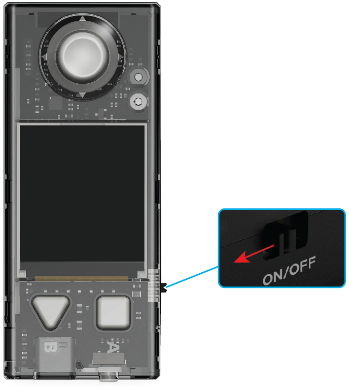
- Press the button on the wireless adapter.
The indicator on it blinks fast. The wireless adapter enters the pairing state.
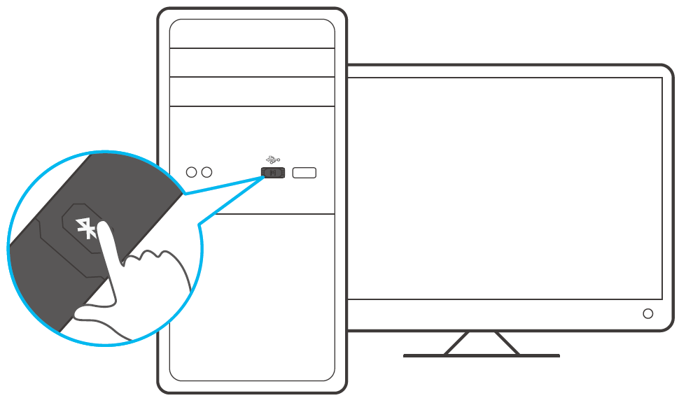
- Place CyberPi close to the wireless adapter.
The pairing is automatically performed.
The indicator on the wireless adapter keeps on, indicating that the pairing is successful.
Software connection
After a device is successfully paired with the wireless adapter, you need to connect it to mBlock 5 before you program it.
In this example, CyberPi is the device to be programmed.
Click Connect, select the serial port used by the wireless adapter in the dialog box that appears, and click Connect.
A message is displayed after the device is connected, indicating that the connection is successful.
Now, you can start to program CyberPi on mBlock 5!
Water Pump
With the specified connection cables, the water pump can work together with Pocket Shield, mBot2, and DC motor drivers.
Driven by Pocket Shield, mBot2, or a DC motor driver, the water pump draws water or blows air to control the flow of water.
:::info Note:
- The water pump must be used in combination with a tube that supports it.
- The water pump can't be used in water. :::
Compatibility description
| Driven by | With | Remarks |
|---|---|---|
| DC motor port—Pocket Shield | | |
| **Note: **After you connect the water pump to Pocket Shield, mBot2 Shield, or mBuild DC motor driver, set the output power of the port, to which the water pump is connected, to a positive value when you program it on mBlock 5. Otherwise, the water pump can't work properly. | ||
| DC motor port—mBot2 Shield | ||
| mBuild DC motor driver | | |
| DC motor driver port that supports the voltage output of 5 V and peak current output of higher than 1 A | Connect them through soldering or use a connection cable that supports the driver |
Fan
With the specified connection cables, the fan can work together with Pocket Shield, mBot2, and DC motor drivers.
Driven by Pocket Shield, mBot2, or a DC motor driver, the fan can run clockwise or counterclockwise to control the wind power and direction.
Compatibility description
| Driven by | With |
|---|---|
| DC motor port—Pocket Shield | |
|
| DC motor port—mBot2 Shield | |
| mBuild DC motor driver | |
| DC motor driver port that supports the voltage output of 5 V and peak current output of higher than 1 A | Connect them through welding or use a connection cable that supports the driver |
MS-1.5A Servo
The MS-1.5A servo is developed independently by Makeblock. Its dimensions are similar to common 9g servos.
Function comparison
| MS-1.5A servo | Earlier 9g servos | |
|---|---|---|
| Servo hub mounted before delivery | Yes | No |
| Supporting quick fitting | Yes | No |
| Compatible with Makeblock metal parts and Lego blocks | Yes | Yes, but adapter brackets required |
| Physical limit | No (The circuits are redesigned to better protect the servo and thus ensuring longer service life.) | Yes |
Connection example
Dimensions (in millimeters)
Specifications
With the latest technology in the servo industry, the MS-1.5 servo provides significantly improved performance. The following describes its specifications.
Electrical specifications (performance parameters)
| Item | 4.6 V | 6.0 V |
|---|---|---|
| Operating speed (without load) | 0.11 ± 0.01 sec/60° | 0.10 ± 0.01 sec/60° |
| Operating current (without load) | 270 mA ± 50 mA | 380 mA ± 50 mA |
| Stall torque (when locked) | 1.5 kg ± 0.30 kg·cm | 1.8 kg ± 0.30 kg·cm |
| Stall current (when locked) | 1200 mA ± 50 mA | 1500 mA ± 70 mA |
| Idle current (when stopped) | 4 mA ± 1 mA | 4 mA ± 1 mA |
| Service life (without load) | > 180 thousand times | > 150 thousand times |
:::info Note: The servo operates without load when the average value of item 2 is defined. :::
Mechanical specifications
| Item | Specification |
|---|---|
| Overall dimensions | See "Dimensions." |
| Limit angle | No |
| Weight | Subject to the actual weight |
| Wire specification | JST 2.54mm #30 PVC black-white-red |
| Wire length | 260 ± 5 mm (connectors not included) |
| Horn specification | 20T |
| Horn type | N/A |
| Excessive play | ≤ 1° |
Control specifications
| Item | Specification |
|---|---|
| Control system | N/A |
| Amplifier type | N/A |
| Operating travel | 180°± 5° (500 to 2500 µ sec) |
| Left-right travelling angle deviation | ≤ 5° |
| Centering deviation | ≤ 1° |
| Neutral position | N/A |
| Dead band width | N/A |
| Rotating direction | Counterclockwise (500 to 2500 µ sec) |
| Pulse width range | 500 to 2500 µ sec |
| Maximum travel | About 180° (500 to 2500 µ sec) |
9g Micro Servo (Metal Gear)
Makeblock 9g Micro Servo (metal gear) is a high-quality servo customized by Makeblock. It may be delivered assembled or unassembled in a pack, including the following four parts: 9g micro servo (metal gear), servo horn, screw, and servo holder.
Dimensions
Parameters
| Electrical specifications | ||
|---|---|---|
| Item | 4.8 V | 6.0 V |
| Operating speed (without load) | 0.15±0.015 sec/60° | 0.13±0.015 sec/60° |
| Running current (without load) | 80±35 mA | 90±35 mA |
| Max. load in operation | 1.0±0.05kg·cm | 1.1±0.1kg·cm |
| Stall torque (locked) | 1.5±0.05kg·cm | 1.8±0.1kg·cm |
| Stall current (locked) | 680±40 mA | 750±50 mA |
| Idle current (stopped) | 6±1 mA | 6±1 mA |
| Temperature drift (at 25°C) | ≤5° | ≤7° |
| Mechanical specifications | ||
| Overall dimensions | See "Dimensions." | |
| Limit angle | 180°±10° | |
| Weight | 13.5±0.5g | |
| Connector wire gauge | #28 PVC, black-red-white, plug: 2510-3P, white | |
| Connector wire length | 260±5 mm | |
| Horn gear spline | 40T | |
| Horn type | Double-arm | |
| Reducation ratio | 1/324 | |
| Excessive play | ≤1° | |
| Screw | PM2×5 mm | |
| Control specifications | ||
| Control system | Changing the pulse width | |
| Amplifier type | Analog controller | |
| Operating travel | 180°±10° (600 to 2400 µ sec) | |
| Left & right travelling angle deviation | ≤7° | |
| Centering deviation | ≤1° | |
| Neutral position | 1500 µ sec | |
| Dead band width | ≤7 µ sec | |
| Rotating direction | Counterclockwise (1500 to 2000 µ sec) | |
| Pulse width range | 500 to 2500 µ sec | |
| Max. travel | About 190° (500 to 2500 µ sec) |
High-Speed TT Motor
Makeblock high-speed TT motor is a plastic gearbox motor launched by Makeblock. You can use high-speed TT motors in combination with Makeblock plastic timing pulleys 62T or 90T to build wheel mechanisms in MakeX competitions or various DIY projects.
Specifications
| Item | Description |
|---|---|
| SKU | M2010003000 |
| Rate voltage | 6V DC |
| Operating voltage | 4–8 V DC |
| Current without load | ≤220mA |
| Current with rated load | ≤260mA |
| Rotational speed without load | 15000 RPM±10% |
| Rotational speed with rated load | 310 RPM±10% |
| Gear ratio | 1 : 48 |
| Operating temperature and humidity | –5℃ to + 40℃;15%RH–90%RH |
| Storage temperature and humidity | –10℃ to +50℃;15%RH–90%RH (no condensation) |
Structure and dimensions
TT Dual-Shaft Motor
Makeblock TT dual-shaft motor is a DC plastic gearbox motor that provides dual-shaft output. It supports the DC motor ports of extension boards in the CyberPi series and is applicable to various DIY projects to drive the rotation of any parts (such as wheels) connected to its shafts.
Specifications
| Item | Specification |
|---|---|
| Rated voltage | DC 6 V |
| Speed without load | 200 RPM ± 10% |
| Gear ratio | 1:48 |
Features
- Provides dual-shaft output
- Supports positive nagative rotation
- Provides high-precision control
- Designed in a simple structure, promising low-cost maintenance
Structure and dimensions
Example
180 Optical Encoder Motor
Overview
The 180 optical encoder motor is equipped with an optical encoder that enables high-accuracy control. With two M4 threaded holes on each of the three sides, it can be easily connected to Makeblock mechanical parts and thus can be used flexibly in combination with various other parts. The customized material it uses reduces noise and promises large output torque. It supports multiple motor drivers and main control boards, such as Orion, MegaPi, MegaPi Pro, Me Auriga, and mBot2 Shield.
Electrical performance
| Driving voltage | 5V | 7.4V |
|---|---|---|
| Rotational speed range | 1–207 (RPM) | 0–350 ± 5% (RPM) |
| Rotational precision | ≤ 5° | |
| Detection precision | 1° | |
| Rotational torque | 1,500 g·cm | Start torque: 5,000 g·cm |
| Rated torque: 800 g·cm | ||
| Material of the output shaft | Metal |
Control performance
| Turning | Precise turning |
|---|---|
| Moving straight forward | Deviation: ≤2% |
| Providing the command for moving forward XX mm | |
| Functioning as a servo | Supported |
| Angle control accuracy: ≤5° | |
| Functioning as a knob | Supported |
| Detection accuracy: 1° |
Mechanical specifications
- Reduction gear ratio: 39.6
- Length of the output shaft: 9 mm
LED Strip (0.5 m and 1 m)
Overview
The LED strip (addressable, sealed) comprises a number of addressable RGB LEDs. The 1-meter LED RGB strip includes 30 RGB LEDs. In addition to the characteristics of high brightness and full color, you can also control the color and brightness of each RGB LED individually through programming.
Specifications
- Length of cable: 1 m, 0.5 m
- Operating voltage: 5V DC
- Operating current: 1.8 A/m (Maximum current)
- Operating temperature: –40 to +60℃
- Visible angle: >140°
- Service life: > 50 thousand hours
- Dimension: 1000 x 13 x 3 mm (L x W x H), cable not included
Features
- Providing 256 grades of brightness and 16,777,216 kinds of pure colors
- Fully matching with the Arduino library to make programming easy
- Allowing you to control each LED individually
- Allowing you to change the shape of LED strip to implement different luminous patterns
Mini LED Strip and Ring
Due to the physical port and control protocols, the mini LED strip and ring can work properly only with the mBuild LED driver. Color deviation may be caused if you use a third-party driver to drive the mini LED strip or ring.
LED strip
The LED strip can be used to make a light sword or glowing words, or used to create an atmosphere.
When using the LED strip, connect the IN plug to the LED driver or the OUT plug of another LED, LED strip, or LED ring.
The LED strip is not waterproof. Using it in water may cause damage to it, and such damage is not covered in the warranty.
Parameter
- Dimensions: 8 mm × 112 mm
12-LED ring
When using the LED ring, connect the IN plug to the LED driver or the OUT plug of another LED, LED strip, or LED ring.
The LED strip is not waterproof. Using it in water may cause damage to it, and such damage is not covered in the warranty.
The places of the LEDs on the 12-LED ring are defined in the same way as a clock, as shown in the following figure.
Parameter
- Dimensions: diameter of 45 mm
Compatibility description
| Driven by | With |
|---|---|
| mBuild LED driver | |
M4 Adapter
The M4 adapter is used to connect mBuild modules to other parts with M4 holes or fit mBuild modules together.
Connection examples
Example 1
Example 2
5V Universal Cable
The 5V Universal Wire is used to connect mBuild modules or connect mBuild modules to any main control boards that support mBuild modules. Currently, 10-cm, 20-cm, and 60-cm mBuild cables are provided.
If you need a mBuild cable with another length, you can combine different cables with the extension module.
Extend Module
The extend module can be used to connect two 5V universal cables to form a longer cable.
Connection example
Doodle Boy (Doodle function in detail)
1. Before you start
- The Doodle functions and programs described in this article are based on version 006, make sure both your hardware and software environments are version 006 or above.
- Open mBlock5, add CyberPi to the library, select Extension, and add Display+ extension.
- See Operation Guide of the "Display +" Extension for CyberPi for more details.
2. What is Doodle
Doodle is a feature of the **Display+ **extension that emulates turtle graphics in Python. It is like drawing on paper with a pen. In mBlock5, we can use the Doodle blocks to control stroke weight, coordinates, and other parameters to display personalized patterns on CyberPi.
3. Getting started
3.1 Start doodling
3.1.1 Add Display+
Add CyperPi to the device library and add the "Display+" extension, then you can see the Sprites and Doodle categories as shown below. Connect CyberPi to the computer and you can start programming.
Note: Doodle can only be used in Upload mode
3.1.2. Practice with example
To start doodling after adding the event block, you must also add the Start doodling block. Before you start, you can set the thickness, color, and starting position of the brush. Only moving the brush creates a path, while rotating leaves no trace on the display. After you finish drawing the pattern, you need to add the Finish doodling block to end the program.
Now let's see how to draw a line on the display.
Pseudocode
Blocks
3.1.3 Upload the program
Upload the program to the connected device and you can display the doodle on the display.
3.2 Use the airbrush
The airbrush is very important in Doodle blocks. It works like a brush to draw patterns on the display. You can use the Doodle blocks in mBlock5 to move, rotate and position the brush, and you can use functions and variables to create more complex graphic patterns.
Airbrush functions
You can use the blocks to adjust the direction and coordinates of the airbrush and to set the number of pixels it moves. To draw graphics with Doodle, you need to use the airbrush blocks.
Airbrush blocks
| Function | Blocks | Description |
|---|---|---|
| Color | | You can set the airbrush color in one of the two ways: |
- Select color through the color palette.
- Set the RGB values, 0-255, i.e. from zero light to maximum light. |
| Linear motion | |
The airbrush moves in pixels to draw a straight line. The direction defaults to the right.
|
| Rotational motion | |
You can set the radius and angle to draw different sized circles or arcs.
|
| Angle of rotation | | You can adjust the angle of the airbrush in one of the two ways:
- Click the input box to reveal the dial and drag the arrow to adjust the angle. Here the airbrush points in direction 90°, parallel to the positive direction of the X-axis.
- Enter a specified degree by which the airbrush rotates clockwise. The airbrush arrow faces right by default and changes after each time of angle adjustment. The angle direction you see is the one after the last adjustment. |
| Positioning | | You can set the starting point of the airbrush in one of the three ways:
- Set it to the display center
- Move it to the specified coordinates. Here (0,0) is on the vertex of the 90-degree angle in the upper-left edge of the display.
- Adjust the parameters. |
4. Block help
If you have any questions while using the block, you can right-click on the block and select Help in the menu.
Alternatively, you can look at Block Help for Display+.
5. Example programs
Doodle ball
Heartbeat ECG
Blockade ball run
Line following with Kp
How does the Quad RGB sensor react when it detects a line?
The quad RGB sensor's four indicators help you quickly know what the sensor have detected - when the background is detected, the indicator lights up; otherwise, the indicator does not light up.
By default, the quad RGB sensor identifies lighter colors as backgrounds and darker colors as lines.
How does the sensor tells a line from a background?
The quad RGB sensor has 4 probes capable of detecting light intensity. They work by actively detecting the intensity of the reflected light after the fill light shines on the object.
The sensor can infer the grayscale value of the object. The higher the grayscale value, the brighter the object is, otherwise the darker it is.
To distinguish between the line and the background, we also need to give the sensor a threshold value, telling the sensor that the colors above or below this threshold are background colors, otherwise they are lines. In this way, the sensor can distinguish between backgrounds and lines.
By default, we set a uniform threshold value for the quad RGB sensor, so that you can use it out of the box.
Default threshold value
You can also set a new threshold value or define dark colors as backgrounds by learning
Let the sensor learn new line and background with the learning button
In contests, we often use line following maps with white lines on a black background (which makes the map more durable) or other combinations of background and line colors. In these cases, we need to use the calibration function of the quad RGB sensor.
The learning feature enables the quad RGB sensor to find the fill light color and threshold value that best matches the current ambient light, background color, and line color. The methods are as follows.
-
Double-click: trigger the line following learning.
- Place the two probes of the sensor on the background of the line following map, and double-click the learning button.
- When you see the two line following indicators flashing rapidly, at a fixed height on the background, shake the sensor until the indicators stop flashing rapidly (this will take about 2.5 seconds).
- The learning parameters will be automatically stored. If the learning failed, the two line following indicators will turn to slow flashing and you need to relearn.
-
Long press: switch the color of the fill light (generally, you don't need to switch the color of the fill light, it will be set automatically after successful learning)
Write a simple line following program
First let's look at a simple line following program.
Repeat
	If (the head of the mBot is aligned with the line)
		The mBot goes straight ahead
	If (the head of the mBot is on the left side of the line).
		The mBot turns right at an angle
	If (the head of the mBot is on the right side of the line).
		The mBot turns left at an angle
Note that this program does not yet discuss what to do when the mBot deviates from the line, so let me nest an if-else statement to solve that problem.
Repeat
  If
		If (the head of the mBot is aligned with the line)
			The mBot goes straight ahead
		If (the head of the mBot is on the left side of the line).
			The mBot turns right at an angle
		If (the head of the mBot is on the right side of the line).
			The mBot turns left at an angle
  Else
    The mBot stops
There are also blocks for steering the mBot.
Read the position of the mBot relative to the line from the line following status
With the correct definition of the line and background color, we can better understand the line following status of the quad RGB sensor.
The quad RGB sensor consists of 4-bit binary numbers reading from 0000 to 1111, corresponding to the decimal numbers 0 to 15. The binary numbers, from high to low, correspond to the line and the background results detected by the L2, L1, R1, R2 sensors. When the sensor detects a backgroud color, the corresponding bit reads 1, otherwise, it reads 0. The following is a summary of the reading status and sensor detection results.
| Line following status
(Decimal) | Line following status
(Binary) | L2 status | L1 status | R1 status | R2 status | Illustration (black lines on a white background) |
| --- | --- | --- | --- | --- | --- | --- |
| 0 | 0000 | Line | Line | Line | Line | |
| 1 | 0001 | Line | Line | Line | Background | |
| 2 | 0010 | Line | Line | Background | Line | |
| 3 | 0011 | Line | Line | Background | Background | |
| 4 | 0100 | Line | Background | Line | Line | |
| 5 | 0101 | Line | Background | Line | Background | |
| 6 | 0110 | Line | Background | Background | Line | |
| 7 | 0111 | Line | Background | Background | Background | |
| 8 | 1000 | Background | Line | Line | Line | |
| 9 | 1001 | Background | Line | Line | Background | |
| 10 | 1010 | Background | Line | Background | Line | |
| 11 | 1011 | Background | Line | Background | Background | |
| 12 | 1100 | Background | Background | Line | Line | |
| 13 | 1101 | Background | Background | Line | Background | |
| 14 | 1110 | Background | Background | Background | Line | |
| 15 | 1111 | Background | Background | Background | Background | |
Read the position of the mBot relative to the line from the deviation value
Based on the grayscale value reading of the sensor probes L1 and R1, along with the color definition for the line and the _background _by the sensor, the sensor is able to calculate the deviation of mBot from the center of the line.
- When the sensor is on the left side of the line, the deviation value < 0; in this case, the head of the mBot needs to turn right, and the left wheels of the mBot should accelerate; the right wheels should decelerate.
- When the sensor is on the right side of the line, the deviation value > 0; in this case, the head of the mBot needs to turn left, and the left wheels of the mBot should decelerate; the right wheels should accelerate.
Combining the motor speed setting principle of the mBot chassis, and the forward speed definition of the encoder motor (counterclockwise is forward speed), it can be seen that if the mBot needs to move forward in a straight line with base_speed, the left wheels need to rotate counterclockwise; the right wheels need to rotate clockwise. We can set the speed of the encoder motor as follows: Left wheel: base_speed, right wheel: -1*base_speed.
Therefore, the deviation value can be used to dynamically increase or decrease the motor speed for smoother line following.
When the sensor is on the left side of the line, the deviation value < 0; in this case, the head of the mBot needs to turn right, and the left wheels of the mBot should accelerate; left_speed = base_speed + absolute value * deviation value = base_speed - deviation value the right wheels should decelerate, right_speed = -1*(base_speed-absolute value(deviation value))=-1*(base_speed+deviation value)
When the sensor is on the right side of the line, the deviation value > 0; in this case, the head of the mBot needs to turn left, and the left wheels of the mBot should decelerate; left_speed = base_speed - absolute value * deviation value = base_speed - deviation value The right wheels should accelerate, right_speed = -1*(base_speed+absolute value(deviation value))=-1*(base_speed+deviation value)
To sum up, we can get the formula for setting motor speed during line following. left_speed = base_speed - offset value right_speed =-1*(base_speed+offset)
The base_speed is the base speed of the mBot following line, and the deviation value is the mBot's position in relation to the line as inferred by the line following sensor.
Apply the concept of Kp
Although very crude, with **left_speed=base_speed-deviation value ** *right_speed =-1(base_speed+deviation value ** a simple closed-loop control is implemented. The motor RPM controls the movement of the mBot, which changes its position relative to the line. The position of the mBot is sensed by the quad RGB sensor and caculated as a deviation value, and finally we use the deviation value to set a new motor RPM for the mBot.
However, if we use the above formula directly, we can easily find that the actual results is not satisfactory. We know that we need to turn right when the mBot deviates left, but if it does not turn right or turns too far, it will not be able to achieve a better line following result. We need a parameter to control the effect of the deviation value on the degree of turning. This is where the proportional controller "Kp" comes into play.
In the more complex robot control algorithm, engineers often introduce integrating and differential proportional controlleror to smooth out the entire control process. However, this is much more complex and we will not expand on it here.
With the Kp concept, we can rewrite the original formula as follows left_speed=base_speed-Kpdeviation value ** *right_speed =-1(base_speed+Kpdeviation value)
In general, the larger the base_speed, the larger the Kp value will need to be to prevent the mBot from not turning in time, while the smaller the base_speed, the smaller the Kp will need to be to prevent over-turning. There is no fixed Kp setting, but rather you should choose the value for your situation and needs.
Introduction to the 2024 MakeX Inspire Smart Logistics Arena and Frame
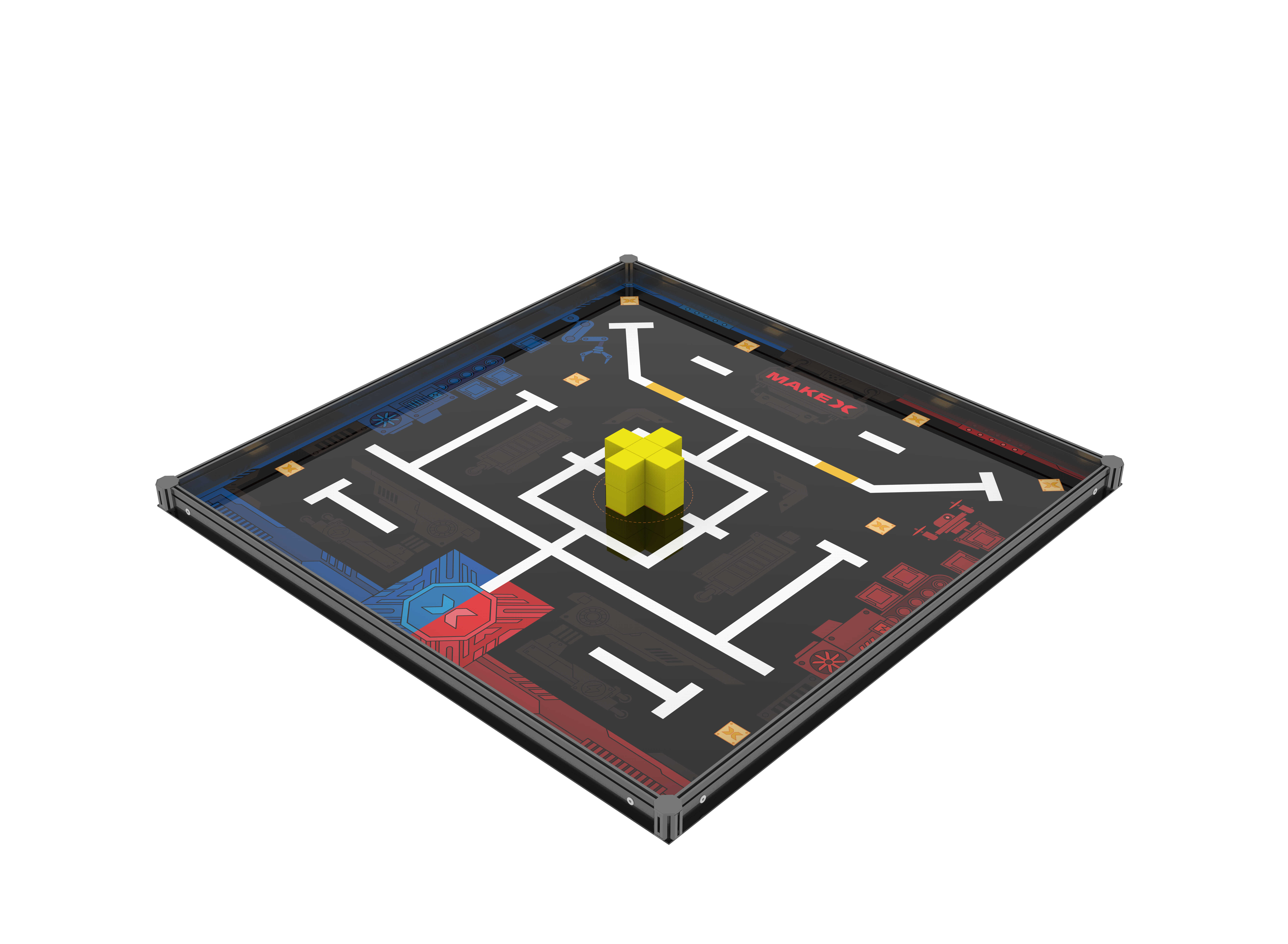
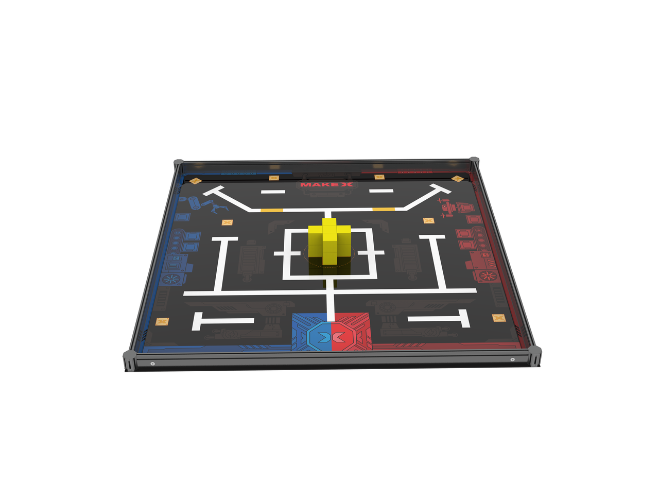
1. Basic information
| Name | 2024 MakeX Inspire Smart Logistics Arena and Frame |
|---|---|
| SKU | P1090047 |
| EAN | 6928819519138 |
| Package type | Paper box |
| Package size (mm) | 1280×180×70 |
| Gross weight (including packaging) | 4.76 kg (10.49 lb) |
| Others | Competition equipment not included |
2. Overview
If this is your first MakeX Inspire competition, or if you would like to purchase a complete package for practice or hosting a MakeX competition, purchase the** 2024 MakeX Inspire Smart Logistics Arena and Frame**.
3. Parts list
Make sure the following parts are included in the kit. If there is any missing part, contact our after-sales service or distributors.
| Name | Quantity |
|---|---|
| Flat beam 1550-1173 | 4 |
| Octogonal pillar-45 | 4 |
| Octogonal pillar cover | 8 |
| Flat beam lock | 8 |
| Yellow cube 50 mm | 12 |
| Hex Allen key T30 | 1 |
| Map | 1 |
4. Assembly instructions
After checking the number of parts, refer to the following document to assemble the 2024 MakeX Inspire Smart Logistics Arena. 2024 MakeX Inspire Smart Logistics Arena Assembly Instructions.pdf
5. More information
Introduction to the 2024 MakeX Competitions and Kits mBlock 5 Online Help Introduction to mBot2 mBot2 Operation Guide
Introduction to the 2024 MakeX Starter All-Core Journey Educational Competition Kit
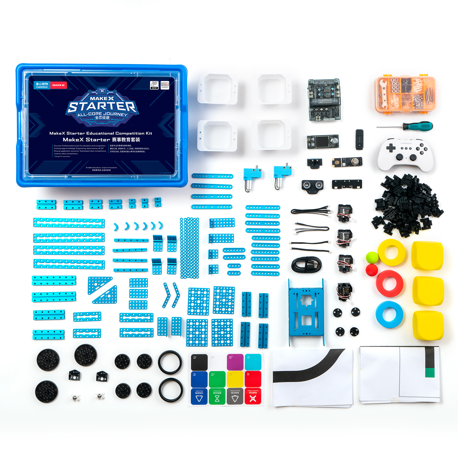
1. Basic information
| Name | 2024 MakeX Starter All-Core Journey Educational Competition Kit |
|---|---|
| SKU | P1090048 |
| EAN | 193122018579 |
| Package type | Plastic box |
| Package size (mm) | 420×305×160 |
| Gross weight (including packaging) | 3.22 kg (7.1 lb) |
| Others | Remote control and battery included |
2. Overview
The 2024 MakeX Starter All-Core Journey Educational Competition Kit covers cutting-edge knowledge in engineering, data science, AI, and IoT. It is suitable for classroom teaching, student club activities, and multi-task and creative robotics competitions. The product supports multi-threaded graphical and Python programming. It features built-in Wi-Fi and Bluetooth, allowing for swift switching between Live and Upload modes. This functionality facilitates easier classroom teaching.
3. Parts list
| Name | Quantity | **cumentation |
|---|---|---|
| CyberPi | 1 | For technical information on CyberPi, see CyberPi. |
| For the operation guide of CyberPi, see CyberPi Operation Guide. | ||
| mBot2 shield | 1 | For technical information on mBot2 shield, see mBot2 Shield. |
| Bluetooth dongle | 1 | For the operation guide of Bluetooth dongle, see Wireless Adapter. |
| Ultrasonic sensor 2 | 1 | For technical information on ultrasonic sensor 2, see Ultrasonic Sensor 2. |
| Quad RGB sensor | 1 | For technical information on quad RGB sensor, see Quad RGB Sensor. |
| Dual RGB color sensor | 1 | For technical information on dual RGB color sensor, see Dual RGB Color Sensor. |
| Science sensor | 1 | For technical information on science sensor, see Science Sensor. |
| Servo MS-1.5A | 4 | For technical information on servo MS-1.5A, see Servo MS-1.5A. |
| 180 optical encoder motor | 2 | For technical information on 180 optical encoder motor, see 180 Optical Encoder Motor. |
| Bluetooth controller | 1 | For technical information on Bluetooth controller, see Bluetooth Controller. |
| Cable for 180 optical encoder motor (180 mm) | 2 |
- The kit uses CNC machined aluminum connecting pieces for strong structures and tight fits.
- The kit is compatible with a wide range of industry standard parts, making it perfect for various industrial applications.
For information on beams (12 types, 37 items), see Slide Beam 0824 Beam 0808 Square Beam 2424
For information on brackets (4 types, 10 items), see Brackets.
For information on linkages (8 types, 25 items), see Linkages.[
](https://www.yuque.com/makeblock-help-center-zh/maker_platform/dkpslp) | | mBuild cable (100 mm) | 2 | | | mBuild cable (200 mm) | 3 | | | USB cable (Type-C) | 1 | | | mBot2 chassis | 1 | | | Slide beam-016 | 3 | | | Slide beam-032 | 2 | | | Slide beam-048 | 2 | | | Slide beam-064 | 4 | | | Slide beam-080 | 2 | | | Slide beam-112 | 2 | | | Square beam-088 | 4 | | | Beam-036 | 2 | | | Beam-060 | 2 | | | Beam-076 | 6 | | | Beam-092 | 4 | | | Beam-108 | 4 | | | Plate-072 | 2 | | | Plate-088 | 2 | | | Plate-184 | 4 | | | Bracket 33 | 2 | | | Bracket 36 | 2 | | | Bracket 38 | 2 | | | Bracket 33120° | 4 | | | Plate 36 | 3 | | | Triangle plate 68 | 2 | | | Plate 79-B | 4 | | | Plate 45° | 2 | | | Cuttable linkage | 6 | | | Black plastic timing pulley 62T with step | 4 | | | Black plastic timing pulley 90T with step | 3 | | | Slick tire | 2 | | | Mini wheel | 2 | | | Track | 50 | | | Track axle 30 mm | 50 | | | Cross screw M2.512 | 4 | | | Screw M48 | 50 | | | Screw M414 | 30 | | | Screw M425 | 16 | | | Screw M430 | 4 | | | Screw M435 | 6 | | | Headless screw M35 | 10 | | | Hex nut M4 | 60 | | | Hex lock nut M4 | 20 | | | Plastic ring 472 mm | 20 | | | Plastic ring 4710 mm | 20 | | | Plastic rivet-R4060 | 20 | | | Plastic rivet-R4120 | 10 | | | Plastic cup | 4 | | | Green ball 32 mm | 1 | | | Red ball 32 mm | 1 | | | Yellow cube 70 mm | 3 | | | Item sticker | 1 | | | Line-following map | 1 | | | Junction map | 1 | | | Screwdriver hex 2.5 mm & cross | 1 | | | Wrench 5 mm & 7 mm | 1 | | | Hex key 1.5 mm | 1 | | | Screw box | 1 | | | Mini injection omni wheel | 2 | | | Blue ring 407020 mm | 1 | | | Yellow ring 407020 mm | 1 | | | Red ring 407020 mm | 1 | | | D shaft 456 mm | 4 | | | Shaft collar | 8 | | | Brass stud M4*(8+6) | 2 | | | Stiffener 1616-008-M4 | 6 | |
4. About the competition
MakeX is an international robotics competition and education platform that promotes multidisciplinary learning within the fields of science and technology. It aims at building a world where STEAM education is highly appreciated and where young people are passionate about innovation by engaging them in activities such as exciting robotics competitions, STEAM carnivals, tech events, and educational conferences.
MakeX Starter is a multi-task event for elementary school students aged 6-13 years. The event integrates the automatic stage and the manual stage, which makes it more fun and engaging. The independent missions and alliance missions fully exercise the critical thinking and strategic planning abilities of contestants, and enhance the collaboration between alliance teams.
 To view information about registration, entry requirements, and available competitions, visit www.makex.cc/en or contact us by email: makex_overseas@makeblock.com (overseas)
makex@makeblock.com (China)
To view information about registration, entry requirements, and available competitions, visit www.makex.cc/en or contact us by email: makex_overseas@makeblock.com (overseas)
makex@makeblock.com (China)
5. More information
Getting Started with the 2024 MakeX Starter All-Core Journey Educational Competition Kit Introduction to the 2024 MakeX Competitions and Kits mBlock 5 Online Help mBot2 Operation Guide mBlock-Python Editor Online Help Python API Documentation for CyberPi
Getting Started with the 2024 MakeX Starter All-Core Journey Educational Competition Kit
 Thank you for choosing the 2024 MakeX Starter All-Core Journey Educational Competition Kit. If you are using this kit for the first time, we recommended that you read these instructions carefully to get the most out of it.
1. Unpack and check
Make sure the following parts are included in the kit. If there is any missing part, contact our after-sales service or distributors.
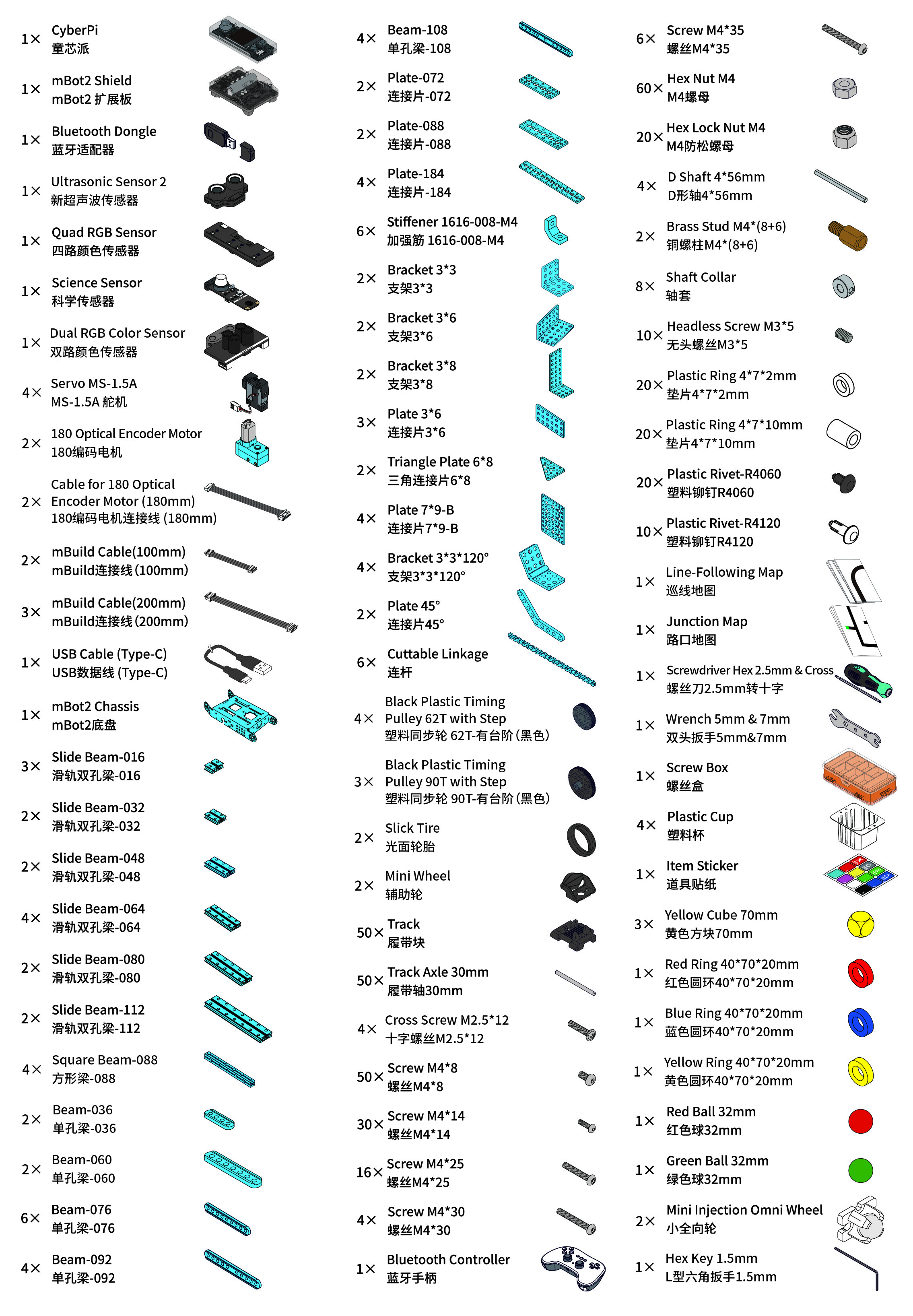 :::warning
Note: Keep the parts properly after each use so that you can reuse them in other projects.
:::
:::warning
Note: Keep the parts properly after each use so that you can reuse them in other projects.
:::
2. Learn about the main components
The kit includes a main control board named CyberPi and an mBot2 shield. They work together to power and control other electronic parts, including encoder motors, servos, and sensors.
| Name | Quantity | Documentation |
|---|---|---|
| CyberPi | 1 | For technical information on CyberPi, see CyberPi. |
| For the operation guide of CyberPi, see CyberPi Operation Guide. | ||
| mBot2 shield | 1 | For technical information on mBot2 shield, see mBot2 Shield. |
| Bluetooth controller | 1 | For technical information on Bluetooth controller, see Bluetooth Controller. |
| Bluetooth dongle | 1 | For the operation guide of Bluetooth dongle, see Wireless Adapter. |
| Ultrasonic sensor 2 | 1 | For technical information on ultrasonic sensor 2, see Ultrasonic Sensor 2. |
| Quad RGB sensor | 1 | For technical information on quad RGB sensor, see Quad RGB Sensor. |
| Dual RGB color sensor | 1 | For technical information on dual RGB color sensor, see Dual RGB Color Sensor. |
| Science sensor | 1 | For technical information on science sensor, see Science Sensor. |
| Servo MS-1.5A | 4 | For technical information on servo MS-1.5A, see Servo MS-1.5A. |
| 180 optical encoder motor | 2 | For technical information on 180 optical encoder motor, see 180 Optical Encoder Motor. |
3. Explore beyond
You can use the parts to build your own robot and program it using mBlock 5 to bring your ideas to life.
3.1 Programming guide
To program the parts in mBlock 5, you need to add the corresponding extensions first.
For example, if you use a CyberPi, an mBot2 shield, encoder motors, and an ultrasonic sensor 2 to build the robot, after adding **CyberPi **to the device library and connecting it, you need to add the mBot2 shield extension (which contains the blocks for encoder motors) and the Ultrasonic Sensor 2 extension.

 Alternatively, you can add mBot2 to the device library to load the required extensions in one go.
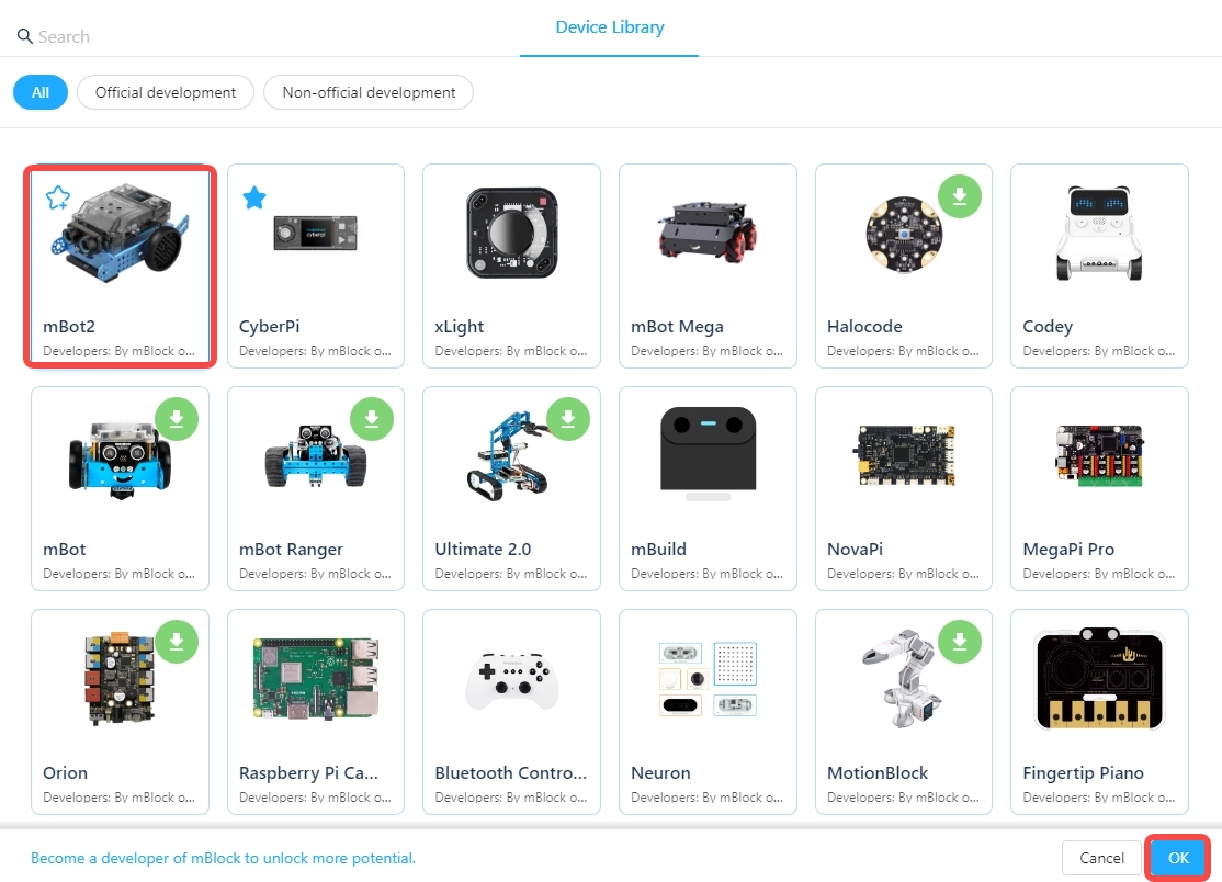
After adding the extensions successfully, you can drag the blocks to the Blocks area and start programming.

3.2 Get more hardware
There is a wide range of peripherals that can be added to the kit to bring your ideas to life. Contact us if you want to take them home.
You can also find more technical information from our CyberPi Series User Manual.
4. About the competition
MakeX is an international robotics competition and education platform that promotes multidisciplinary learning within the fields of science and technology. It aims at building a world where STEAM education is highly appreciated and where young people are passionate about innovation by engaging them in activities such as exciting robotics competitions, STEAM carnivals, tech events, and educational conferences.
MakeX Starter is a multi-task event for elementary school students aged 6-13 years. The event integrates the automatic stage and the manual stage, which makes it more fun and engaging. The independent missions and alliance missions fully exercise the critical thinking and strategic planning abilities of contestants, and enhance the collaboration between alliance teams.
 To view information about registration, entry requirements, and available competitions, visit www.makex.cc/en or contact us by email: makex_overseas@makeblock.com (overseas)
makex@makeblock.com (China)
To view information about registration, entry requirements, and available competitions, visit www.makex.cc/en or contact us by email: makex_overseas@makeblock.com (overseas)
makex@makeblock.com (China)
5. Online support
If you encounter any product quality issues or find any parts missing when you open the package, contact us for after-sales services at support@makeblock.com.
We would also appreciate it if you could give us your feedback on the product at cyber.list@makeblock.com.
6. More information
Introduction to the 2024 MakeX Starter All-Core Journey Educational Competition Kit Introduction to the 2024 MakeX Competitions and Kits mBlock 5 Online Help mBot2 Operation Guide CyberPi Operation Guide mBlock-Python Editor Online Help Python API Documentation for CyberPi
Introduction to the 2024 MakeX Starter Upgrade Kit
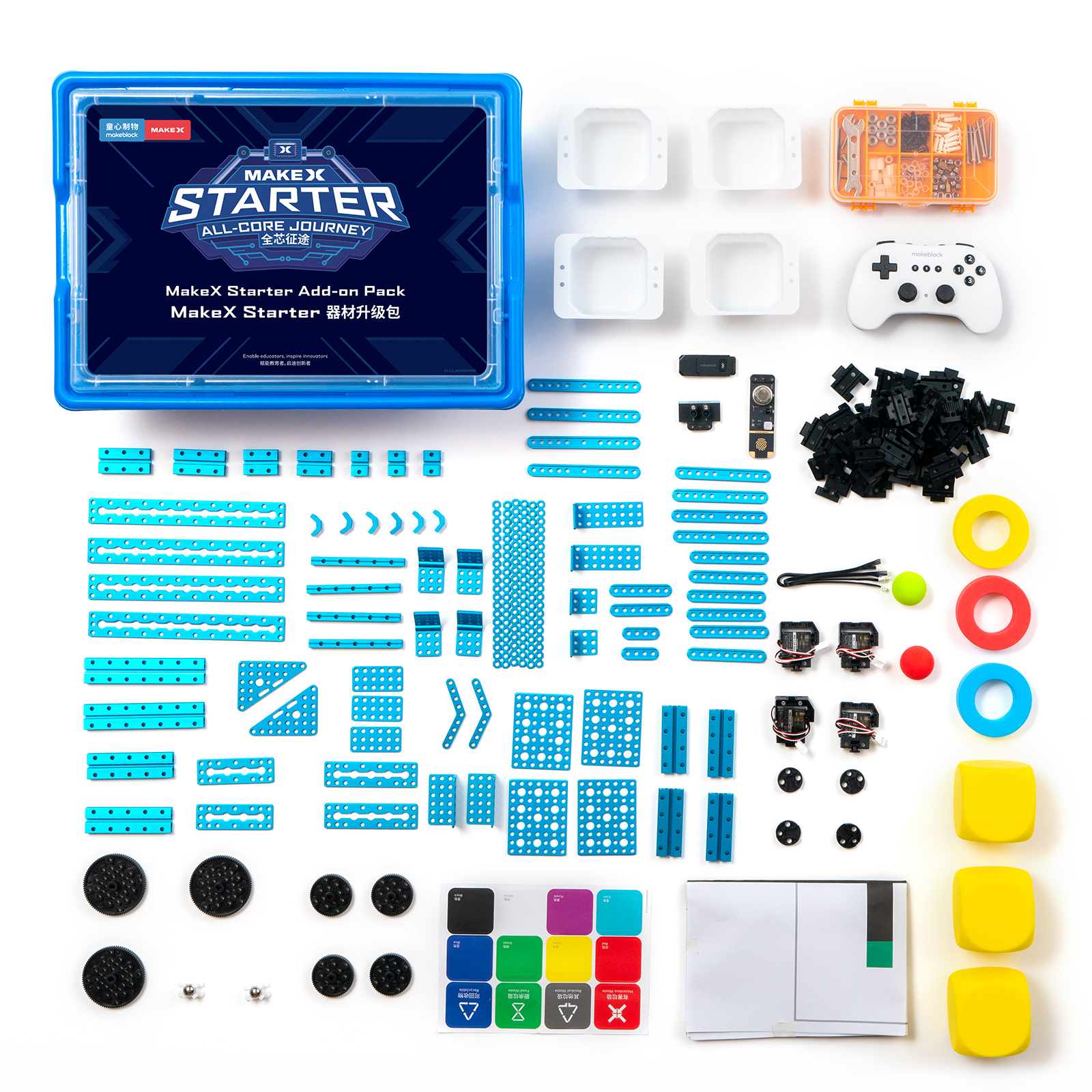
1. Basic information
| Name | 2024 MakeX Starter Upgrade Kit |
|---|---|
| SKU | P1090049 |
| EAN | 193122018586 |
| Package type | Plastic box |
| Package size (mm) | 420×305×160 |
| Gross weight (including packaging) | 2.56 kg (5.64 lb) |
| Others | Remote control included, battery not included |
2. Overview
The 2024 MakeX Starter Upgrade Kit can work with mBot2 or the 2022 MakeX Starter Educational Competition Kit. Together, they constitute the 2024 MakeX Starter All-Core Journey Educational Competition Kit. This upgrade kit is suitable for those who already have an mBot2 or those who want to customize their kit for the 2024 MakeX Starter competition.
For more information, see Introduction to the 2024 MakeX Starter All-Core Journey Educational Competition Kit.
3. Parts list
| Name | Quantity | Documentation |
|---|---|---|
| Bluetooth dongle | 1 | For the operation guide of Bluetooth dongle, see Wireless Adapter. |
| Science sensor | 1 | For technical information on science sensor, see Science Sensor. |
| Dual RGB color sensor | 1 | For technical information on dual RGB color sensor, see Dual RGB Color Sensor. |
| Servo MS-1.5A | 4 | For technical information on servo MS-1.5A, see Servo MS-1.5A. |
| Bluetooth controller | 1 | For technical information on Bluetooth controller, see Bluetooth Controller. |
| mBuild cable (200 mm) | 3 |
- The kit uses CNC machined aluminum connecting pieces for strong structures and tight fits.
- The kit is compatible with a wide range of industry standard parts, making it perfect for various industrial applications.
For information on beams (12 types, 37 items), see Slide Beam 0824 Beam 0808 Square Beam 2424
For information on brackets (4 types, 10 items), see Brackets.
For information on linkages (8 types, 25 items), see Linkages.
[
](https://www.yuque.com/makeblock-help-center-zh/maker_platform/dkpslp) | | Slide beam-016 | 3 | | | Slide beam-032 | 2 | | | Slide beam-048 | 2 | | | Slide beam-064 | 4 | | | Slide beam-080 | 2 | | | Slide beam-112 | 2 | | | Square beam-088 | 4 | | | Beam-036 | 2 | | | Beam-060 | 2 | | | Beam-076 | 6 | | | Beam-092 | 4 | | | Beam-108 | 4 | | | Bracket 33 | 2 | | | Bracket 36 | 2 | | | Bracket 38 | 2 | | | Bracket 33120° | 4 | | | Plate-072 | 2 | | | Plate-088 | 2 | | | Plate-184 | 4 | | | Plate 36 | 3 | | | Triangle plate 68 | 2 | | | Plate 79-B | 4 | | | Plate 45° | 2 | | | Cuttable linkage | 6 | | | Black plastic timing pulley 62T with step | 4 | | | Black plastic timing pulley 90T with step | 3 | | | Track | 50 | | | Track axle 30 mm | 50 | | | Screw M48 | 50 | | | Screw M414 | 30 | | | Screw M425 | 16 | | | Screw M430 | 4 | | | Screw M435 | 6 | | | Headless screw M35 | 10 | | | Hex nut M4 | 60 | | | Hex lock nut M4 | 20 | | | Plastic ring 472 mm | 20 | | | Plastic ring 4710 mm | 20 | | | Plastic rivet-R4060 | 20 | | | Plastic rivet-R4120 | 10 | | | Plastic cup | 4 | | | Green ball 32 mm | 1 | | | Red ball 32 mm | 1 | | | Yellow cube 70 mm | 3 | | | Blue ring 407020 mm | 1 | | | Yellow ring 407020 mm | 1 | | | Red ring 407020 mm | 1 | | | Item sticker | 1 | | | Junction map | 1 | | | Wrench 5 mm & 7 mm | 1 | | | Hex key 1.5 mm | 1 | | | Screw box | 1 | | | Mini injection omni wheel | 2 | | | D shaft 456 mm | 4 | | | Shaft collar | 8 | | | Brass stud M4(8+6) | 2 | | | Stiffener 1616-008-M4 | 6 | |
4. About the competition
MakeX is an international robotics competition and education platform that promotes multidisciplinary learning within the fields of science and technology. It aims at building a world where STEAM education is highly appreciated and where young people are passionate about innovation by engaging them in activities such as exciting robotics competitions, STEAM carnivals, tech events, and educational conferences.
MakeX Starter is a multi-task event for elementary school students aged 6-13 years. The event integrates the automatic stage and the manual stage, which makes it more fun and engaging. The independent missions and alliance missions fully exercise the critical thinking and strategic planning abilities of contestants, and enhance the collaboration between alliance teams.
 To view information about registration, entry requirements, and available competitions, visit www.makex.cc/en or contact us by email: makex_overseas@makeblock.com (overseas)
makex@makeblock.com (China)
To view information about registration, entry requirements, and available competitions, visit www.makex.cc/en or contact us by email: makex_overseas@makeblock.com (overseas)
makex@makeblock.com (China)
5. More information
Introduction to the 2024 MakeX Competitions and Kits Getting Started with the 2024 MakeX Starter Upgrade Kit Introduction to the 2024 MakeX Starter All-Core Journey Educational Competition Kit Getting Started with the 2024 MakeX Starter All-Core Journey Educational Competition Kit mBlock 5 Online Help mBot2 Operation Guide CyberPi Operation Guide CyberPi Series User Manual mBlock-Python Editor Online Help Python API Documentation for CyberPi
Getting Started with the 2024 MakeX Starter Upgrade Kit
 Thank you for choosing the 2024 MakeX Starter Upgrade Kit. The 2024 MakeX Starter Upgrade Kit can work with mBot2. Together, they constitute the 2024 MakeX Starter All-Core Journey Educational Competition Kit. If you are using this pack for the first time, we recommend that you read these instructions carefully to get the most out of it.
1. Unpack and check
Make sure the following parts are included in the pack. If there is any missing part, contact our after-sales service or distributors.
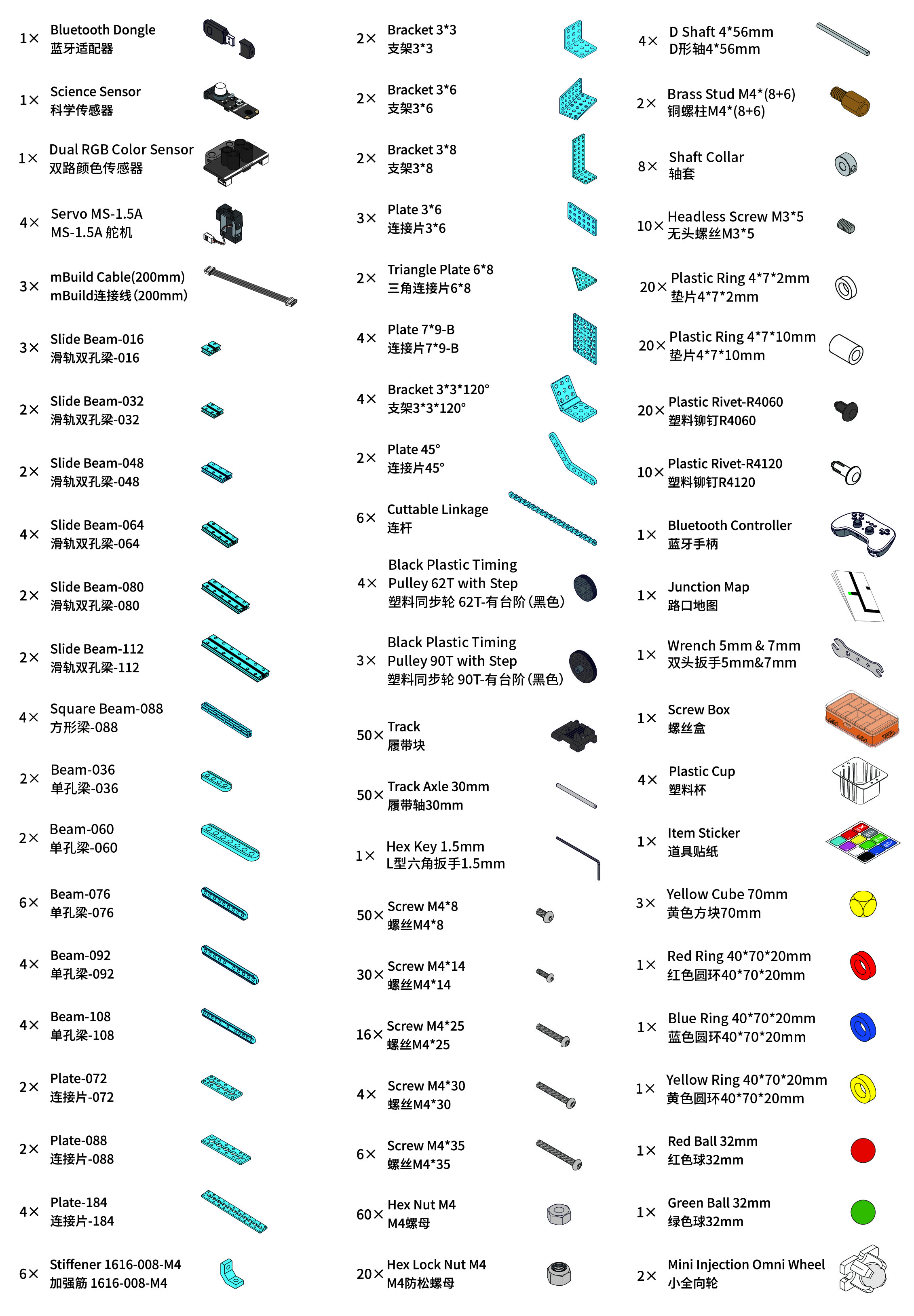 :::warning
Note: Keep the parts properly after each use so that you can reuse them in other projects.
:::
:::warning
Note: Keep the parts properly after each use so that you can reuse them in other projects.
:::
2. Learn about the main components
| Name | Quantity | Documentation |
|---|---|---|
| Bluetooth dongle | 1 | For the operation guide of Bluetooth dongle, see Wireless Adapter. |
| Science sensor | 1 | For technical information on science sensor, see Science Sensor. |
| Dual RGB color sensor | 1 | For technical information on dual RGB color sensor, see Dual RGB Color Sensor. |
| Servo MS-1.5A | 4 | For technical information on servo MS-1.5A, see Servo MS-1.5A. |
| Bluetooth controller | 1 | For technical information on Bluetooth controller, see Bluetooth Controller. |
3. Explore beyond
You can use the parts to build your own robot and program it using mBlock 5 to bring your ideas to life.
3.1 Programming guide
To program the parts in mBlock 5, you need to add the corresponding extensions first.
For example, if you use a CyberPi, an mBot2 shield, encoder motors, and an ultrasonic sensor 2 to build the robot, after adding **CyberPi **to the device library and connecting it, you need to add the mBot2 shield extension (which contains the blocks for encoder motors) and the Ultrasonic Sensor 2 extension.

 Alternatively, you can add mBot2 to the device library to load the required extensions in one go.
 After adding the extensions successfully, you can drag the blocks to the Blocks area and start programming.

3.2 Get more hardware
There is a wide range of peripherals that can be added to the pack to bring your ideas to life. Contact us if you want to take them home.
You can also find more technical information from our CyberPi Series User Manual.
4. About the competition
MakeX is an international robotics competition and education platform that promotes multidisciplinary learning within the fields of science and technology. It aims at building a world where STEAM education is highly appreciated and where young people are passionate about innovation by engaging them in activities such as exciting robotics competitions, STEAM carnivals, tech events, and educational conferences.
MakeX Starter is a multi-task event for elementary school students aged 6-13 years. The event integrates the automatic stage and the manual stage, which makes it more fun and engaging. The independent missions and alliance missions fully exercise the critical thinking and strategic planning abilities of contestants, and enhance the collaboration between alliance teams.
 To view information about registration, entry requirements, and available competitions, visit www.makex.cc/en or contact us by email: makex_overseas@makeblock.com (overseas)
makex@makeblock.com (China)
To view information about registration, entry requirements, and available competitions, visit www.makex.cc/en or contact us by email: makex_overseas@makeblock.com (overseas)
makex@makeblock.com (China)
5. Online support
If you encounter any product quality issues or find any parts missing when you open the package, contact us for after-sales services at support@makeblock.com.
We would also appreciate it if you could give us your feedback on the product at cyber.list@makeblock.com.
6. More information
Introduction to the 2024 MakeX Starter Upgrade Kit Introduction to the 2024 MakeX Competitions and Kits Introduction to the 2024 MakeX Starter All-Core Journey Educational Competition Kit mBlock 5 Online Help mBot2 Operation Guide CyberPi Operation Guide CyberPi Series User Manual mBlock-Python Editor Online Help Python API Documentation for CyberPi
Introduction to the 2024 MakeX Starter All-Core Journey Arena and Frame
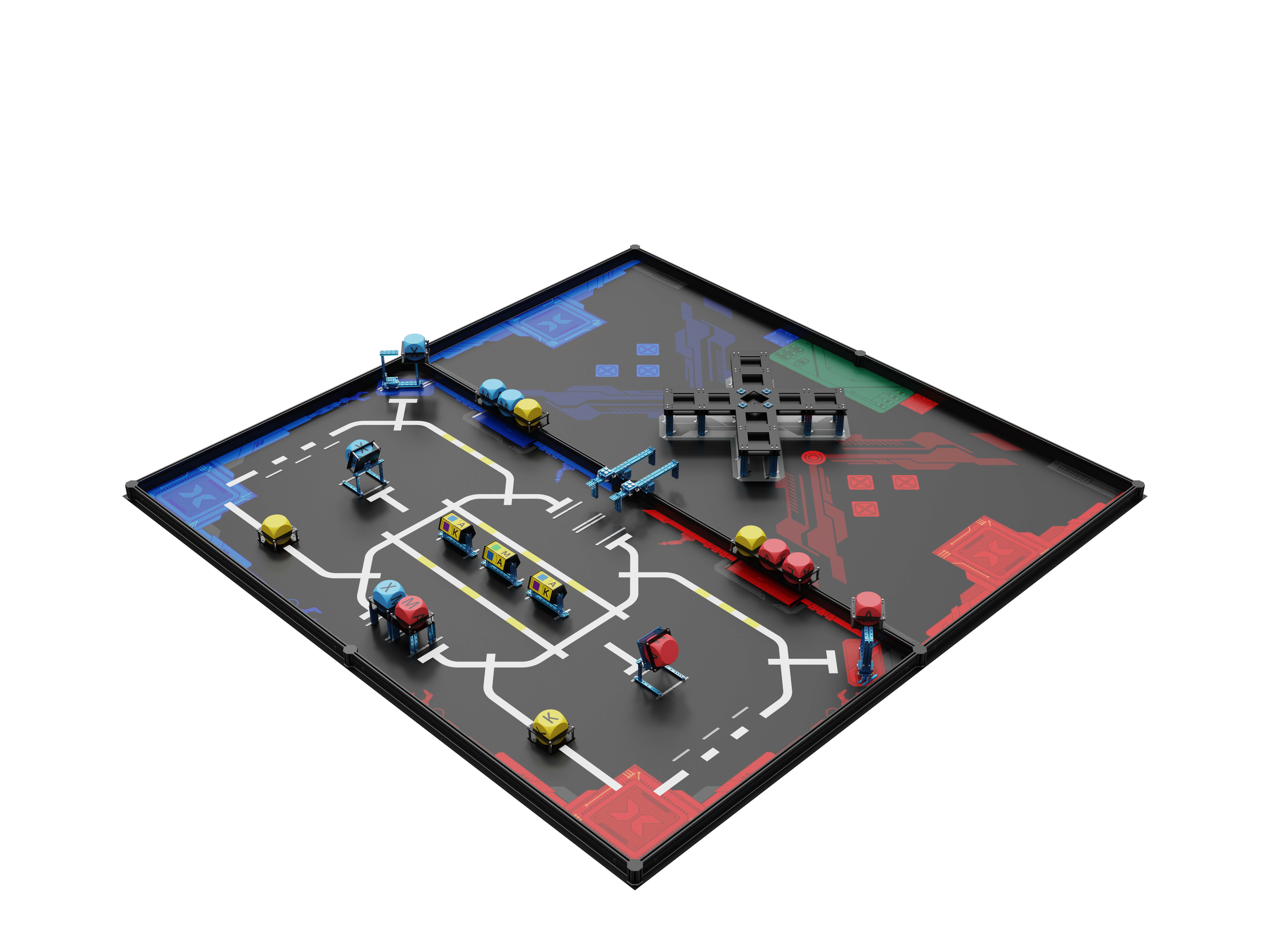 This kit does not include the MakeboX.
1. Basic information
| Name | 2024 MakeX Starter All-Core Journey Arena and Frame |
|---|---|
| SKU | P1090050 |
| EAN | 193122018555 |
| Package type | Paper box |
| Package size (mm) | 90×90×1260 (map) |
| 1220×135×120 (beams) | |
| 634×394×205 (other parts) | |
| Gross weight (including packaging) | 20.14 kg (44.4 lb) |
| Others | Remote control and battery not included |
2. Overview
If this is your first MakeX Starter competition, or if you would like to purchase a complete package for practice or hosting a MakeX competition, purchase the** 2024 MakeX Starter All-Core Journey Arena and Frame**.
3. Parts list
Make sure the following parts are included in the kit. If there is any missing part, contact our after-sales service or distributors.
| Name | Quantity |
|---|---|
| Board A | 4 |
| Board B | 4 |
| Board C | 2 |
| Board D | 2 |
| Square board A | 2 |
| Square board B | 6 |
| Square board C | 8 |
| Rotor board A | 15 |
| Rotor board B | 6 |
| Square beam 0808 - 072 | 4 |
| Slide beam - 016 | 4 |
| Slide beam - 064 | 14 |
| Square beam 2424 - 088 | 20 |
| Slide beam - 112 | 7 |
| Slide beam - 128 | 2 |
| Slide beam - 256 | 2 |
| Beam - 108 | 4 |
| Beam - 124 | 2 |
| Fixing plate | 4 |
| Slider | 4 |
| Double-sided fabric tape | 1 |
| Hinge 40*24 mm | 2 |
| Flat beam 1126 | 12 |
| Flat beam lock | 24 |
| Octagonal pillar - 45 | 12 |
| Octagonal pillar cover | 24 |
| Bracket 3*3 | 4 |
| Bracket 3*8 | 6 |
| Rudder bracket | 2 |
| U-shaped bracket | 2 |
| Magnetic stud M4 | 150 |
| Magnetic disc | 150 |
| Rectangular nut M4 | 16 |
| Square magnetic plate | 100 |
| Hex nut M4 | 64 |
| Hex lock nut M4 | 24 |
| Screw M4*8 | 120 |
| Screw M4*10 | 70 |
| Screw M4*14 | 40 |
| Screw M4*16 | 16 |
| Screw M4*22 | 30 |
| Headless screw M3*5 | 15 |
| Roller | 16 |
| Shaft collar | 10 |
| D shaft 4*128 mm | 3 |
| D shaft 4*50 mm | 2 |
| Brass stud M4*16 | 50 |
| Brass stud M4*25 | 10 |
| Hex stud M4*32 | 40 |
| Plastic ring M4710 | 25 |
| Plastic ring M473 | 10 |
| Plastic ring M472 | 15 |
| Plastic rivet - R4060 | 10 |
| Hex key 1.5 mm | 1 |
| Hex Allen key T30 | 1 |
| Screwdriver hex 2.5 mm & cross | 1 |
| Wrench | 1 |
| Rubber magnet sticker | 2 |
| Red cube 70 mm | 5 |
| Blue cube 70 mm | 5 |
| Yellow cube 70 mm | 3 |
| Yellow cube (with K) 70 mm | 1 |
| Sticker | 3 |
| Map | 1 |
| Red ring 407020 mm | 2 |
| Yellow ring 407020 mm | 2 |
| Blue ring 407020 mm | 2 |
| MakeX blue ball | 3 |
| MakeX red ball | 3 |
| Rubber magnet | 6 |
4. Assembly instructions
After checking the number of parts, refer to the following document to assemble the 2024 MakeX Starter All-Core Journey Arena. 2024 MakeX Starter All-Core Journey Arena Assembly Instructions.pdf
5. More information
Introduction to the 2024 MakeX Competitions and Kits Introduction to the 2024 MakeX Starter All-Core Journey Educational Competition Kit Getting Started with the 2024 MakeX Starter All-Core Journey Educational Competition Kit mBlock 5 Online Help mBot2 Operation Guide CyberPi Operation Guide CyberPi Series User Manual mBlock-Python Editor Online Help Python API Documentation for CyberPi
Introduction to the 2024 MakeX Starter Arena Upgrade Kit - Zero Carbon
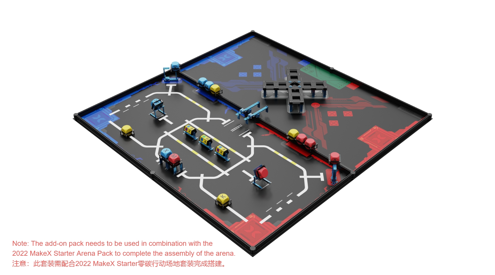 This kit does not include the MakeboX.
1. Basic information
| Name | 2024 MakeX Starter Arena Upgrade Kit - Zero Carbon |
|---|---|
| SKU | P1090051 |
| EAN | 193122018562 |
| Package type | Paper box |
| Package size (mm) | 90×90×1260 (map) |
| 634×394×205 (other parts) | |
| Gross weight (including packaging) | 10.46 kg (23.06 lb) |
| Others | Remote control and battery not included |
2. Overview
This kit is designed for users with the 2022 MakeX Starter Zero Carbon Kit. With this kit, they can participate in the 2024 competition.
3. Parts list
Make sure the following parts are included in the kit. If there is any missing part, contact our after-sales service or distributors.
| Name | Quantity |
|---|---|
| Board A | 4 |
| Board B | 4 |
| Board C | 2 |
| Board D | 2 |
| Square board A | 2 |
| Square board B | 6 |
| Square board C | 8 |
| Rotor board A | 15 |
| Rotor board B | 6 |
| Square beam 0808 - 072 | 4 |
| Slide beam - 016 | 4 |
| Slide beam - 064 | 14 |
| Square beam 2424 - 088 | 20 |
| Slide beam - 112 | 7 |
| Slide beam - 128 | 2 |
| Slide beam - 256 | 2 |
| Beam - 108 | 4 |
| Beam - 124 | 2 |
| Fixing plate | 4 |
| Slider | 4 |
| Hinge 40*24 mm | 2 |
| Bracket 3*3 | 4 |
| Bracket 3*8 | 6 |
| Rudder bracket | 2 |
| U-shaped bracket | 2 |
| Magnetic stud M4 | 150 |
| Magnetic disc | 150 |
| Rectangular nut M4 | 16 |
| Square magnetic plate | 100 |
| Hex nut M4 | 64 |
| Hex lock nut M4 | 24 |
| Screw M4*8 | 120 |
| Screw M4*10 | 70 |
| Screw M4*14 | 40 |
| Screw M4*16 | 16 |
| Screw M4*22 | 30 |
| Headless screw M3*5 | 15 |
| Roller | 16 |
| Shaft collar | 10 |
| D shaft 4*128 mm | 3 |
| D shaft 4*50 mm | 2 |
| Brass stud M4*16 | 50 |
| Brass stud M4*25 | 10 |
| Hex stud M4*32 | 40 |
| Plastic ring M4710 | 25 |
| Plastic ring M473 | 10 |
| Plastic ring M472 | 15 |
| Plastic rivet - R4060 | 10 |
| Hex key 1.5 mm | 1 |
| Rubber magnet sticker | 2 |
| Red cube 70 mm | 5 |
| Blue cube 70 mm | 5 |
| Yellow cube 70 mm | 3 |
| Yellow cube (with K) 70 mm | 1 |
| Sticker | 3 |
| Map | 1 |
| Red ring 407020 mm | 2 |
| Yellow ring 407020 mm | 2 |
| Blue ring 407020 mm | 2 |
| MakeX blue ball | 3 |
| MakeX red ball | 3 |
| Rubber magnet | 6 |
4. Assembly instructions
After checking the number of parts, refer to the following document to assemble the 2024 MakeX Starter All-Core Journey Arena. 2024 MakeX Starter All-Core Journey Arena Assembly Instructions.pdf
5. More information
Introduction to the 2024 MakeX Competitions and Kits Introduction to the 2024 MakeX Starter All-Core Journey Arena and Frame Introduction to the 2024 MakeX Starter All-Core Journey Educational Competition Kit Getting Started with the 2024 MakeX Starter All-Core Journey Educational Competition Kit mBlock 5 Online Help mBot2 Operation Guide CyberPi Operation Guide CyberPi Series User Manual mBlock-Python Editor Online Help Python API Documentation for CyberPi
Introduction to the 2024 MakeX Explorer Digital Pioneer Educational Competition Kit
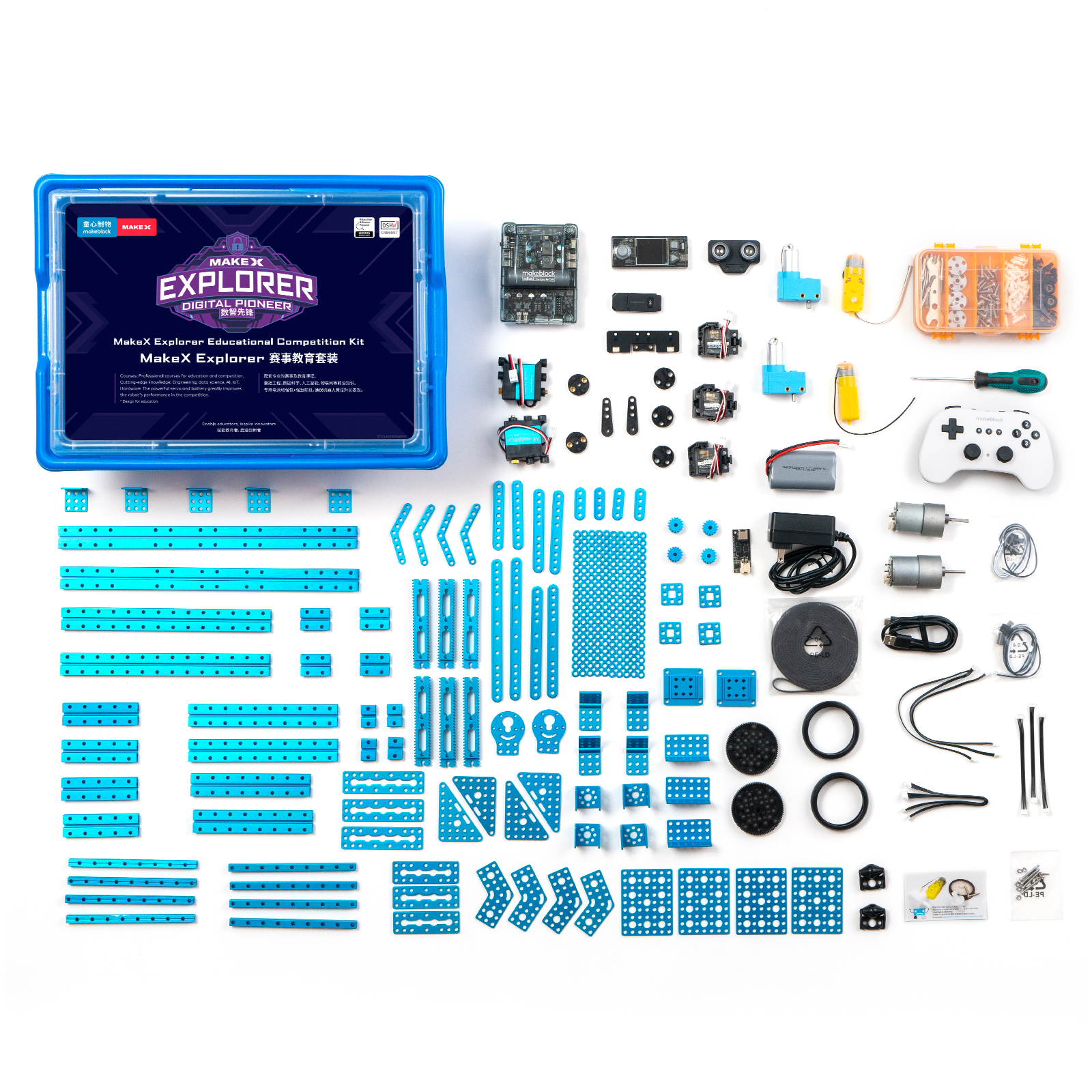
1. Basic information
| Name | 2024 MakeX Explorer Digital Pioneer Educational Competition Kit |
|---|---|
| SKU | P1090052 |
| EAN | 193122018616 |
| Package type | Plastic box |
| Package size (mm) | 420×305×160 |
| Gross weight (including packaging) | 4.42 kg (9.74 lb) |
| Others | Remote control and battery included |
2. Overview
The 2024 MakeX Explorer Digital Pioneer Educational Competition Kit features:
- abundant mechanical parts, allowing you to build robots in multiple forms and with multiple functions.
- expanded batteries and an enhanced battery pack, promising longer battery life.
- high-performance motors, significantly improving the performance of robots in competitions.
It supports block-based, Python, and multi-threaded programming.
3. Parts list
| Name | Quantity | Documentation |
|---|---|---|
| CyberPi | 1 | For technical information on CyberPi, see CyberPi. |
| For the operation guide of CyberPi, see CyberPi Operation Guide. | ||
| mBot2 shield | 1 | For technical information on mBot2 shield, see mBot2 Shield. |
| Bluetooth controller | 1 | For technical information on Bluetooth controller, see Bluetooth Controller. |
| Bluetooth dongle | 1 | For the operation guide of Bluetooth dongle, see Wireless Adapter. |
| Ultrasonic sensor 2 | 1 | For technical information on ultrasonic sensor 2, see Ultrasonic Sensor 2. |
| Quad RGB sensor | 1 | For technical information on quad RGB sensor, see Quad RGB Sensor. |
| Servo MS-1.5A | 3 | For technical information on servo MS-1.5A, see Servo MS-1.5A. |
| Servo MECDS-150 | 2 | For technical information on servo MECDS-150, see Servo MECDS-150. |
| High-speed TT motor | 2 | For technical information on high-speed TT motor, see High-Speed TT Motor. |
| Li-ion rechargeable battery | 1 | For technical information on mBot2 LiPo rechargeable battery enhancement pack, see mBot2 LiPo Rechargeable Battery Enhancement Pack. |
| Battery charger adapter board | 1 | |
| Power adapter | 1 | |
| 180 optical encoder motor | 2 | For technical information on 180 optical encoder motor, see 180 Optical Encoder Motor. |
| Cable for 180 optical encoder motor (180 mm) | 2 | |
| DC motor-37 (50 RPM) | 1 | For technical information on DC motor-37, see DC Motor-37. |
| DC motor-37 (200 RPM) | 1 | |
| Mini wheel | 2 |
- The kit uses CNC machined aluminum connecting pieces for strong structures and tight fits.
- The kit is compatible with a wide range of industry standard parts, making it perfect for various industrial applications.
For information on beams (14 types, 40 items), see Slide Beam 0824 Beam 0808 Square Beam 2424
For information on brackets (5 types, 18 items), see Brackets.
For information on linkages (7 types, 32 items), see Linkages. | | USB cable (Type-C) | 1 | | | mBuild cable (100 mm) | 3 | | | mBuild cable (200 mm) | 3 | | | Bracket 33120° | 4 | | | Bracket 33 | 5 | | | Bracket 36 | 3 | | | Bracket U1 | 4 | | | DC motor-37 bracket | 2 | | | Plate-072 | 3 | | | Plate-088 | 3 | | | Plate 35120° | 4 | | | Plate 45° | 4 | | | Plate 79-B | 4 | | | Triangle plate 68 | 4 | | | Cuttable linkage | 10 | | | Square beam-136 | 4 | | | Slide beam-016 | 4 | | | Slide beam-032 | 4 | | | Slide beam-080 | 4 | | | Slide beam-128 | 2 | | | Slide beam-160 | 2 | | | Slide beam-224 | 2 | | | Slide beam-320 | 2 | | | Beam-036 | 4 | | | Beam-076 | 2 | | | Beam-092 | 2 | | | Beam-124 | 2 | | | Beam-136 | 4 | | | Beam-156 | 2 | | | Flange bearing 483 mm | 6 | | | Slick tire | 2 | | | D shaft 456 mm | 4 | | | Shaft collar 4 mm | 8 | | | Shaft connector | 4 | | | Timing pulley 18T | 4 | | | Black plastic timing pulley 90T with step | 2 | | | Plastic rivet-R4060 | 20 | | | Plastic rivet-R4120 | 30 | | | Wrench 5 mm & 7 mm | 1 | | | Hex key 1.5 mm | 1 | | | Screwdriver hex 2.5 mm & cross | 1 | | | Screw box | 1 | | | Headless screw M35 | 20 | | | Hex lock nut M4 | 16 | | | Hex nut M4 | 64 | | | Screw M2.512 | 6 | | | Screw M48 | 50 | | | Screw M414 | 30 | | | Screw M430 | 25 | | | Flat cross screw M38 | 10 | | | Plastic ring 4710 mm | 12 | | | Brass stud M416+6 | 4 | | | Aluminum sleeve 464 mm | 8 | | | Gear 16T | 4 | | | Roller | 8 | | | Threaded shaft 4*39 mm | 4 | | | Sliding block A1 | 2 | | | PH2.0-2P to stripped-end cable | 2 | | | Double gear rack 31T | 6 | | | Open-ended timing belt (5 m) | 1 | | | Belt connector | 4 | |
4. About the competition
MakeX is an international robotics competition and education platform that promotes multidisciplinary learning within the fields of science and technology. It aims at building a world where STEAM education is highly appreciated and where young people are passionate about innovation by engaging them in activities such as exciting robotics competitions, STEAM carnivals, tech events, and educational conferences.
MakeX Explorer is a competitive event for elementary and junior high school students aged 8-15 years. The event blends the excitement of sports with the intellectual challenge of robot design. It's not just an event, but a captivating spectacle. Participants are tasked with creating robots from scratch, an exercise that hones their skills in robot design, mechanical construction, and programming. Furthermore, the team-based structure of the event fosters strategic thinking and problem-solving abilities among the contestants.
 To view information about registration, entry requirements, and available competitions, visit www.makex.cc/en or contact us by email: makex_overseas@makeblock.com (overseas)
makex@makeblock.com (China)
To view information about registration, entry requirements, and available competitions, visit www.makex.cc/en or contact us by email: makex_overseas@makeblock.com (overseas)
makex@makeblock.com (China)
5. More information
Getting Started with the 2024 MakeX Explorer Digital Pioneer Educational Competition Kit Introduction to the 2024 MakeX Competitions and Kits mBlock 5 Online Help mBot2 Operation Guide mBlock-Python Editor Online Help Python API Documentation for CyberPi
Getting Started with the 2024 MakeX Explorer Digital Pioneer Educational Competition Kit
Thank you for choosing the 2024 MakeX Explorer Digital Pioneer Educational Competition Kit. If you are using this kit for the first time, we recommend that you read these instructions carefully to get the most out of it.
1. Unpack and check
Make sure the following parts are included in the kit. If there is any missing part, contact our after-sales service or distributors.
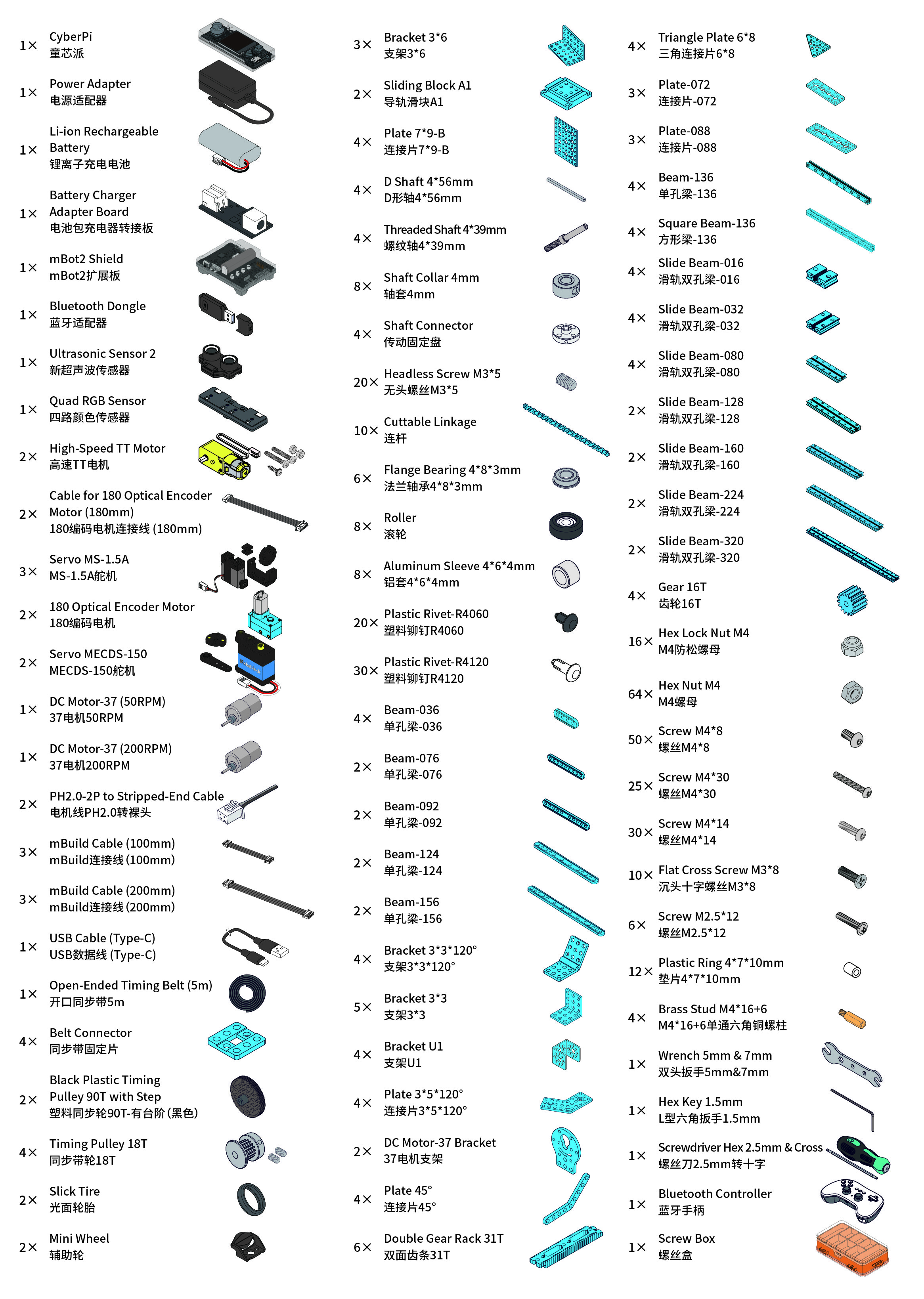 :::warning
Note: Keep the parts properly after each use so that you can reuse them in other projects.
:::warning
Note: Keep the parts properly after each use so that you can reuse them in other projects.
:::
2. Learn about the main components
The kit includes a main control board named CyberPi and an mBot2 shield. They work together to power and control other electronic parts, including encoder motors, servos, and sensors.
| Name | Quantity | Documentation |
|---|---|---|
| CyberPi | 1 | For technical information on CyberPi, see CyberPi. |
| For the operation guide of CyberPi, see CyberPi Operation Guide. | ||
| mBot2 shield | 1 | For technical information on mBot2 shield, see mBot2 Shield. |
| Bluetooth controller | 1 | For technical information on Bluetooth controller, see Bluetooth Controller. |
| Bluetooth dongle | 1 | For the operation guide of Bluetooth dongle, see Wireless Adapter. |
| Ultrasonic sensor 2 | 1 | For technical information on ultrasonic sensor 2, see Ultrasonic Sensor 2. |
| Quad RGB sensor | 1 | For technical information on quad RGB sensor, see Quad RGB Sensor. |
| Servo MS-1.5A | 3 | For technical information on servo MS-1.5A, see Servo MS-1.5A. |
| Servo MECDS-150 | 2 | For technical information on servo MECDS-150, see Servo MECDS-150. |
| High-speed TT motor | 2 | For technical information on high-speed TT motor, see High-Speed TT Motor. |
| Li-ion rechargeable battery | 1 | For technical information on mBot2 LiPo rechargeable battery enhancement pack, see mBot2 LiPo Rechargeable Battery Enhancement Pack. |
| Battery charger adapter board | 1 | |
| Power adapter | 1 | |
| 180 optical encoder motor | 2 | For technical information on 180 optical encoder motor, see 180 Optical Encoder Motor. |
| DC motor-37 (50 RPM) | 1 | For technical information on DC motor-37, see DC Motor-37. |
| DC motor-37 (200 RPM) | 1 |
3. Explore beyond
You can use the parts to build your own robot and program it using mBlock 5 to bring your ideas to life.
3.1 Programming guide
To program the parts in mBlock 5, you need to add the corresponding extensions first.
For example, if you use a CyberPi, an mBot2 shield, encoder motors, and an ultrasonic sensor 2 to build the robot, after adding **CyberPi **to the device library and connecting it, you need to add the mBot2 shield extension (which contains the blocks for encoder motors) and the Ultrasonic Sensor 2 extension.

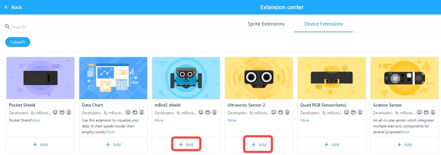 Alternatively, you can add mBot2 to the device library to load the required extensions in one go.
 After adding the extensions successfully, you can drag the blocks to the Blocks area and start programming.

3.2 Get more hardware
There is a wide range of peripherals that can be added to the kit to bring your ideas to life. Contact us if you want to take them home.
You can also find more technical information from our CyberPi Series User Manual.
4. About the competition
MakeX is an international robotics competition and education platform that promotes multidisciplinary learning within the fields of science and technology. It aims at building a world where STEAM education is highly appreciated and where young people are passionate about innovation by engaging them in activities such as exciting robotics competitions, STEAM carnivals, tech events, and educational conferences.
MakeX Explorer is a competitive event for elementary and junior high school students aged 8-15 years. The event blends the excitement of sports with the intellectual challenge of robot design. It's not just an event, but a captivating spectacle. Participants are tasked with creating robots from scratch, an exercise that hones their skills in robot design, mechanical construction, and programming. Furthermore, the team-based structure of the event fosters strategic thinking and problem-solving abilities among the contestants.
 To view information about registration, entry requirements, and available competitions, visit www.makex.cc/en or contact us by email: makex_overseas@makeblock.com (overseas)
makex@makeblock.com (China)
To view information about registration, entry requirements, and available competitions, visit www.makex.cc/en or contact us by email: makex_overseas@makeblock.com (overseas)
makex@makeblock.com (China)
5. Online support
If you encounter any product quality issues or find any parts missing when you open the package, contact us for after-sales services at support@makeblock.com.
We would also appreciate it if you could give us your feedback on the product at cyber.list@makeblock.com.
6. More information
Introduction to the 2024 MakeX Explorer Digital Pioneer Educational Competition Kit Introduction to the 2024 MakeX Competitions and Kits mBlock 5 Online Help mBot2 Operation Guide CyberPi Operation Guide mBlock-Python Editor Online Help Python API Documentation for CyberPi
Introduction to the 2024 MakeX Explorer Upgrade Kit
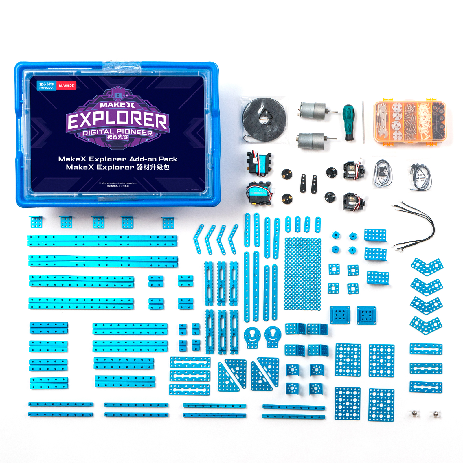
1. Basic information
| Name | 2024 MakeX Explorer Upgrade Kit |
|---|---|
| SKU | P1090053 |
| EAN | 193122018623 |
| Package type | Plastic box |
| Package size (mm) | 420×305×160 |
| Gross weight (including packaging) | 3.36 kg (7.41 lb) |
| Others | Remote control and battery not included |
2. Overview
The 2024 MakeX Explorer Upgrade Kit can work with the 2022 MakeX Explorer Zero Carbon Educational Competition Kit. Together, they constitute the 2024 MakeX Explorer Digital Pioneer Educational Competition Kit. This upgrade kit is suitable for those who want to customize their kit for the 2024 MakeX Explorer competition.
For more information, see Introduction to the 2024 MakeX Explorer Digital Pioneer Educational Competition Kit.
3. Parts list
| Name | Quantity | Documentation |
|---|---|---|
| Servo MS-1.5A | 2 | For technical information on servo MS-1.5A, see Servo MS-1.5A. |
| Servo MECDS-150 | 2 | For technical information on servo MECDS-150, see Servo MECDS-150. |
| DC motor-37 (50 RPM) | 1 | For technical information on DC motor-37, see DC Motor-37. |
| DC motor-37 (200 RPM) | 1 | |
| DC motor-37 bracket | 2 |
- The kit uses CNC machined aluminum connecting pieces for strong structures and tight fits.
- The kit is compatible with a wide range of industry standard parts, making it perfect for various industrial applications.
For information on beams (14 types, 40 items), see Slide Beam 0824 Beam 0808 Square Beam 2424
For information on brackets (5 types, 18 items), see Brackets.
For information on linkages (7 types, 32 items), see Linkages. | | PH2.0-2P to stripped-end cable | 2 | | | mBuild cable (200 mm) | 3 | | | Open-ended timing belt (5 m) | 1 | | | Belt connector | 4 | | | Timing pulley 18T | 4 | | | Gear 16T | 4 | | | Roller | 8 | | | Bracket 33120° | 4 | | | Bracket 33 | 5 | | | Bracket 36 | 3 | | | Bracket U1 | 4 | | | Plate-072 | 3 | | | Plate-088 | 3 | | | Plate 35120° | 4 | | | Plate 45° | 4 | | | Plate 79-B | 4 | | | Triangle plate 68 | 4 | | | Cuttable linkage | 10 | | | Square beam-136 | 4 | | | Slide beam-016 | 4 | | | Slide beam-032 | 4 | | | Slide beam-080 | 4 | | | Slide beam-128 | 2 | | | Slide beam-160 | 2 | | | Slide beam-224 | 2 | | | Slide beam-320 | 2 | | | Beam-036 | 4 | | | Beam-076 | 2 | | | Beam-092 | 2 | | | Beam-124 | 2 | | | Beam-136 | 4 | | | Beam-156 | 2 | | | Sliding block A1 | 2 | | | D shaft 456 mm | 4 | | | Threaded shaft 439 mm | 4 | | | Shaft collar 4 mm | 8 | | | Shaft connector | 4 | | | Headless screw M35 | 20 | | | Screw M48 | 50 | | | Screw M414 | 30 | | | Screw M430 | 25 | | | Flat cross screw M38 | 10 | | | Hex lock nut M4 | 16 | | | Hex nut M4 | 64 | | | Plastic rivet-R4060 | 20 | | | Plastic rivet-R4120 | 30 | | | Plastic ring 4710 mm | 12 | | | Brass stud M416+6 | 4 | | | Wrench 5 mm & 7 mm | 1 | | | Hex key 1.5 mm | 1 | | | Screwdriver hex 2.5 mm & cross | 1 | | | Screw box | 1 | | | Aluminum sleeve 464 mm | 8 | | | Flange bearing 483 mm | 6 | | | Double gear rack 31T | 6 | | | Universal wheel | 2 | |
4. About the competition
MakeX is an international robotics competition and education platform that promotes multidisciplinary learning within the fields of science and technology. It aims at building a world where STEAM education is highly appreciated and where young people are passionate about innovation by engaging them in activities such as exciting robotics competitions, STEAM carnivals, tech events, and educational conferences.
MakeX Explorer is a competitive event for elementary and junior high school students aged 8-15 years. The event blends the excitement of sports with the intellectual challenge of robot design. It's not just an event, but a captivating spectacle. Participants are tasked with creating robots from scratch, an exercise that hones their skills in robot design, mechanical construction, and programming. Furthermore, the team-based structure of the event fosters strategic thinking and problem-solving abilities among the contestants.
 To view information about registration, entry requirements, and available competitions, visit www.makex.cc/en or contact us by email: makex_overseas@makeblock.com (overseas)
makex@makeblock.com (China)
To view information about registration, entry requirements, and available competitions, visit www.makex.cc/en or contact us by email: makex_overseas@makeblock.com (overseas)
makex@makeblock.com (China)
5. More information
Introduction to the 2024 MakeX Competitions and Kits Getting Started with the 2024 MakeX Explorer Upgrade Kit Introduction to the 2024 MakeX Explorer Digital Pioneer Educational Competition Kit Getting Started with the 2024 MakeX Explorer Digital Pioneer Educational Competition Kit mBlock 5 Online Help mBot2 Operation Guide CyberPi Operation Guide mBlock-Python Editor Online Help Python API Documentation for CyberPi
Getting Started with the 2024 MakeX Explorer Upgrade Kit
Thank you for choosing the 2024 MakeX Explorer Upgrade Kit. The 2024 MakeX Explorer Upgrade Kit can work with mBot2. Together, they constitute the 2024 MakeX Explorer Digital Pioneer Educational Competition Kit. If you are using this pack for the first time, we recommend that you read these instructions carefully to get the most out of it.
1. Unpack and check
Make sure the following parts are included in the kit. If there is any missing part, contact our after-sales service or distributors.
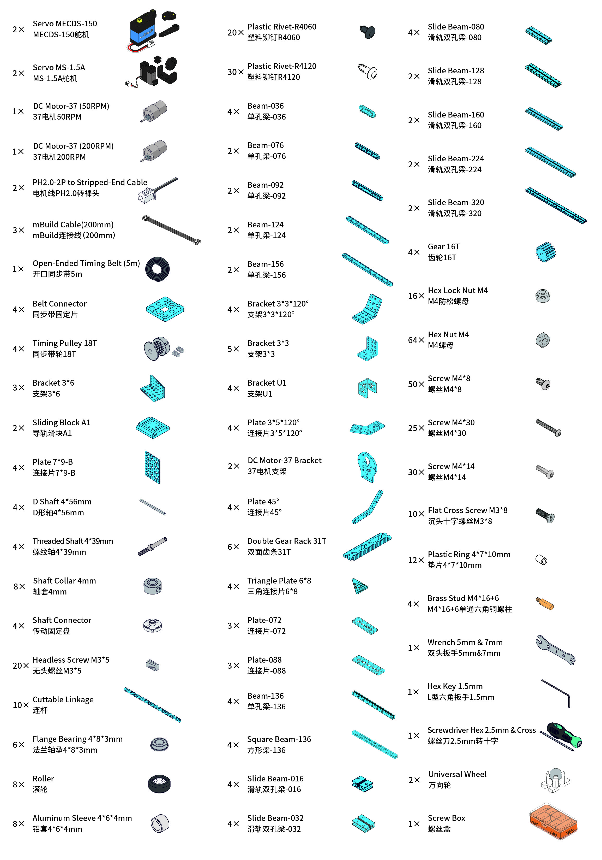 :::warning
Note: Keep the parts properly after each use so that you can reuse them in other projects.
:::warning
Note: Keep the parts properly after each use so that you can reuse them in other projects.
:::
2. Learn about the main components
| Name | Quantity | Documentation |
|---|---|---|
| Servo MS-1.5A | 2 | For technical information on servo MS-1.5A, see Servo MS-1.5A. |
| Servo MECDS-150 | 2 | For technical information on servo MECDS-150, see Servo MECDS-150. |
| DC motor-37 (50 RPM) | 1 | For technical information on DC motor-37, see DC Motor-37. |
| DC motor-37 (200 RPM) | 1 |
3. Explore beyond
You can use the parts to build your own robot and program it using mBlock 5 to bring your ideas to life.
3.1 Programming guide
To program the parts in mBlock 5, you need to add the corresponding extensions first.
For example, if you use a CyberPi, an mBot2 shield, encoder motors, and an ultrasonic sensor 2 to build the robot, after adding **CyberPi **to the device library and connecting it, you need to add the mBot2 shield extension (which contains the blocks for encoder motors) and the Ultrasonic Sensor 2 extension.

 Alternatively, you can add mBot2 to the device library to load the required extensions in one go.
 After adding the extensions successfully, you can drag the blocks to the Blocks area and start programming.

3.2 Get more hardware
There is a wide range of peripherals that can be added to the kit to bring your ideas to life. Contact us if you want to take them home.
You can also find more technical information from our CyberPi Series User Manual.
4. About the competition
MakeX is an international robotics competition and education platform that promotes multidisciplinary learning within the fields of science and technology. It aims at building a world where STEAM education is highly appreciated and where young people are passionate about innovation by engaging them in activities such as exciting robotics competitions, STEAM carnivals, tech events, and educational conferences.
MakeX Explorer is a competitive event for elementary and junior high school students aged 8-15 years. The event blends the excitement of sports with the intellectual challenge of robot design. It's not just an event, but a captivating spectacle. Participants are tasked with creating robots from scratch, an exercise that hones their skills in robot design, mechanical construction, and programming. Furthermore, the team-based structure of the event fosters strategic thinking and problem-solving abilities among the contestants.
 To view information about registration, entry requirements, and available competitions, visit www.makex.cc/en or contact us by email: makex_overseas@makeblock.com (overseas)
makex@makeblock.com (China)
To view information about registration, entry requirements, and available competitions, visit www.makex.cc/en or contact us by email: makex_overseas@makeblock.com (overseas)
makex@makeblock.com (China)
5. Online support
If you encounter any product quality issues or find any parts missing when you open the package, contact us for after-sales services at support@makeblock.com.
We would also appreciate it if you could give us your feedback on the product at cyber.list@makeblock.com.
6. More information
Introduction to the 2024 MakeX Competitions and Kits Introduction to the 2024 MakeX Explorer Upgrade Kit Introduction to the 2024 MakeX Explorer Digital Pioneer Educational Competition Kit Getting Started with the 2024 MakeX Explorer Digital Pioneer Educational Competition Kit mBlock 5 Online Help mBot2 Operation Guide CyberPi Operation Guide mBlock-Python Editor Online Help Python API Documentation for CyberPi
Introduction to the 2024 MakeX Explorer Digital Pioneer Arena and Frame
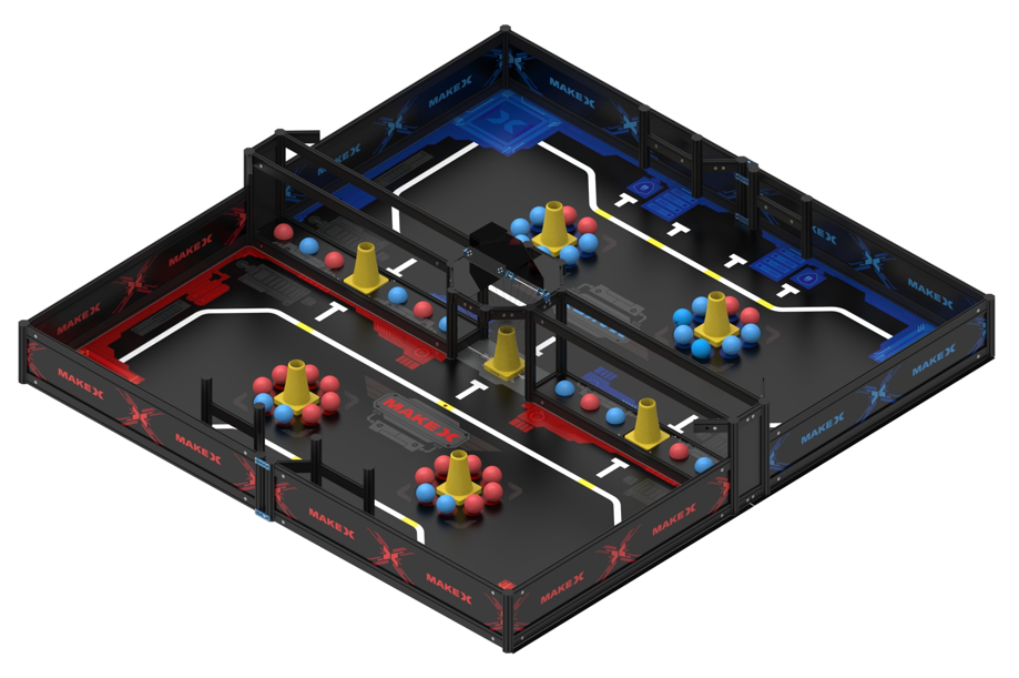 The kit does not include the MakeboX.
1. Basic information
| Name | 2024 MakeX Explorer Digital Pioneer Arena and Frame |
|---|---|
| SKU | P1090054 |
| EAN | 193122018593 |
| Package type | Paper box |
| Package size (mm) | 100×100×1300 (map) |
| 1180×220×120 (frame parts-1) | |
| 1175×210×115 (frame parts-2) | |
| 571×366×364 (other parts) | |
| Gross weight (including packaging) | 41.5 kg (91.49 lb) |
| Others | Remote control and battery not included |
2. Overview
If this is your first MakeX Explorer competition, or if you would like to purchase a complete package for practice or hosting a MakeX competition, purchase the** 2024 MakeX Explorer Digital Pioneer Arena and Frame**.
3. Parts list
Make sure the following parts are included in the kit. If there is any missing part, contact our after-sales service or distributors.
| Name | Quantity |
|---|---|
| Flat beam 1550-120 | 22 |
| Flat beam 1550-220 | 4 |
| Flat beam 1550-960 | 8 |
| Flat beam 1550-1126 | 16 |
| Flat beam 1550-1126 | 16 |
| Octagonal pillar 4040-45 | 4 |
| Octagonal pillar 4040-250 | 16 |
| Octagonal pillar 4040-400 | 8 |
| Octagonal pillar cover | 56 |
| MakeX board blue & black | 4 |
| MakeX board red & black | 4 |
| Board A | 2 |
| Board B | 2 |
| Board C | 2 |
| Board D | 4 |
| MakeboX bracket | 1 |
| Screw M4*8 | 45 |
| Screw M4*14 | 40 |
| Screw M4*16 | 5 |
| Headless hex screw M3*8 | 5 |
| Shaft | 1 |
| Hex nut M4 | 25 |
| Rectangular nut M4 | 45 |
| Shaft collar | 4 |
| Brass stud | 3 |
| Hex stud | 8 |
| Plate | 8 |
| U-shaped bracket | 4 |
| Bracket P3 | 2 |
| Map | 1 |
| Blue ball | 22 |
| Red ball | 22 |
| Yellow cone | 7 |
| Ball net | 1 |
| Hook | 16 |
| Rotatable baffle 90° | 2 |
| Flat beam cover | 4 |
| Double-sided fabric tape | 1 |
| Transparent tape | 1 |
| Wrench 5 mm & 7 mm | 1 |
| Screwdriver hex 2.5 mm & cross | 1 |
| Hex Allen key T30 | 1 |
| Hex key 1.5 mm | 1 |
4. Assembly instructions
After checking the number of parts, refer to the following document to assemble the 2024 MakeX Explorer Digital Pioneer Arena. 2024 MakeX Explorer Digital Pioneer Arena Assembly Instructions.pdf
5. More information
Introduction to the 2024 MakeX Competitions and Kits Introduction to the 2024 MakeX Explorer Digital Pioneer Educational Competition Kit Getting Started with the 2024 MakeX Explorer Digital Pioneer Educational Competition Kit mBlock 5 Online Help mBot2 Operation Guide CyberPi Operation Guide mBlock-Python Editor Online Help Python API Documentation for CyberPi
Introduction to the 2024 MakeX Explorer Arena Upgrade Kit - Eco-Pioneer
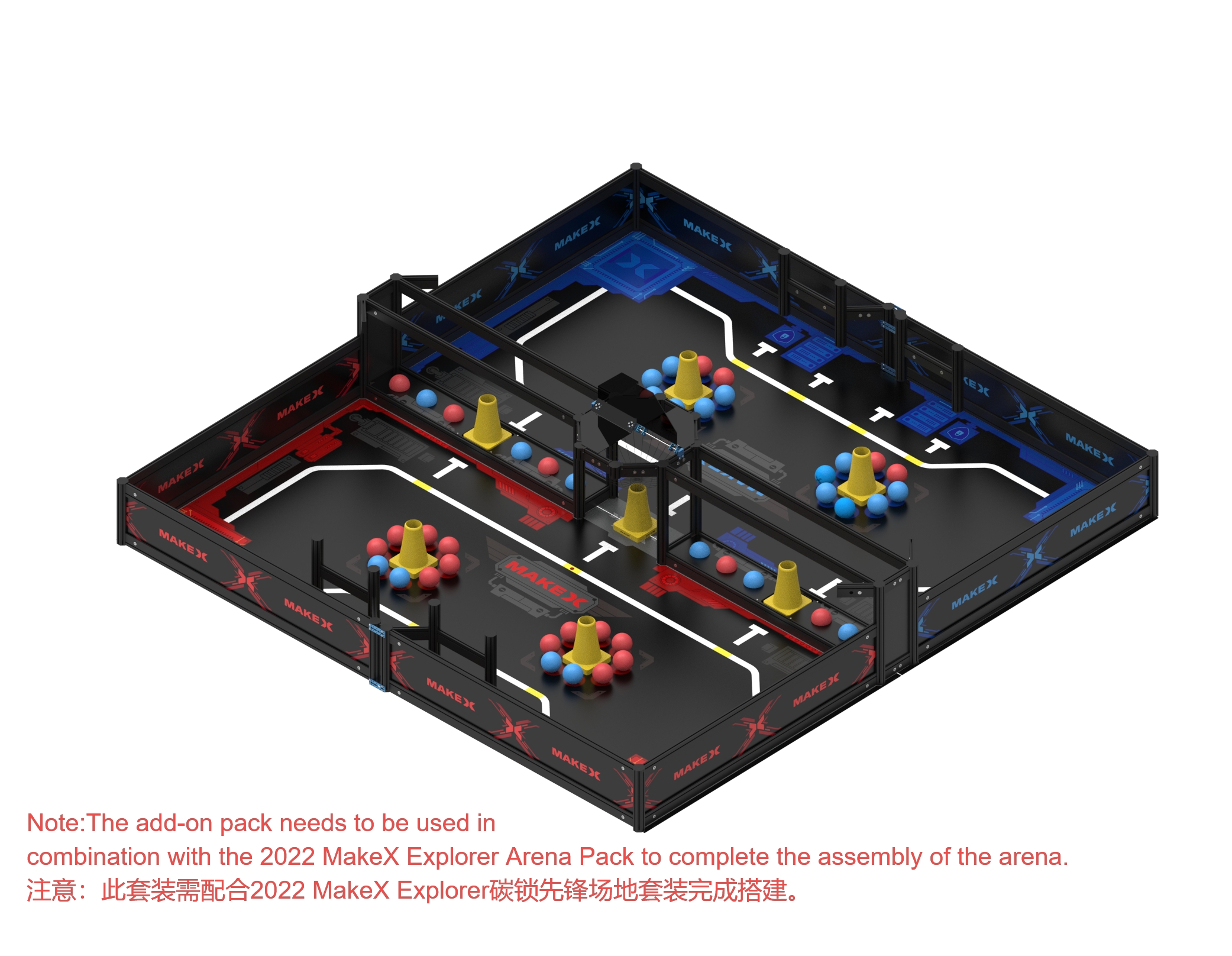 The kit does not include the MakeboX.
1. Basic information
| Name | 2024 MakeX Explorer Arena Upgrade Kit - Eco-Pioneer |
|---|---|
| SKU | P1090055 |
| EAN | 193122018609 |
| Package type | Paper box |
| Package size (mm) | 100×100×1300 (map) |
| 1180×215×120 (frame parts) | |
| 571×366×364 (other parts) | |
| Gross weight (including packaging) | 23.82 kg (52.51 lb) |
| Others | Remote control and battery not included |
2. Overview
This kit is designed for users with the 2022 MakeX Explorer Eco-Pioneer Kit. With this kit, they can participate in the 2024 competition.
3. Parts list
Make sure the following parts are included in the kit. If there is any missing part, contact our after-sales service or distributors.
| Name | Quantity |
|---|---|
| Flat beam 1550-120 | 22 |
| Flat beam 1550-220 | 4 |
| Flat beam 1550-960 | 8 |
| Flat beam lock | 56 |
| Octagonal pillar 4040-45 | 4 |
| Octagonal pillar 4040-250 | 8 |
| Octagonal pillar cover | 20 |
| Board A | 2 |
| Board B | 2 |
| Board C | 2 |
| Board D | 4 |
| Screw M4*8 | 45 |
| Screw M4*14 | 40 |
| Screw M4*16 | 5 |
| Headless hex screw M3*8 | 5 |
| Shaft | 1 |
| Hex nut M4 | 25 |
| Rectangular nut M4 | 45 |
| Shaft collar | 4 |
| Brass stud | 3 |
| Hex stud | 8 |
| Plate | 8 |
| U-shaped bracket | 4 |
| Bracket P3 | 2 |
| Map | 1 |
| Blue ball | 22 |
| Red ball | 22 |
| Yellow cone | 7 |
| Ball net | 1 |
| Hook | 16 |
| Rotatable baffle 90° | 2 |
| Flat beam cover | 4 |
| Double-sided fabric tape | 1 |
| Wrench 5 mm & 7 mm | 1 |
| Screwdriver hex 2.5 mm & cross | 1 |
| Hex Allen key T30 | 1 |
| Hex key 1.5 mm | 1 |
4. Assembly instructions
After checking the number of parts, refer to the following document to assemble the 2024 MakeX Explorer Digital Pioneer Arena. 2024 MakeX Explorer Digital Pioneer Arena Assembly Instructions.pdf
5. More information
Introduction to the 2024 MakeX Competitions and Kits Introduction to the 2024 MakeX Explorer Digital Pioneer Arena and Frame Introduction to the 2024 MakeX Explorer Digital Pioneer Educational Competition Kit Getting Started with the 2024 MakeX Explorer Digital Pioneer Educational Competition Kit mBlock 5 Online Help mBot2 Operation Guide CyberPi Operation Guide mBlock-Python Editor Online Help Python API Documentation for CyberPi
Introduction to the 2024 MakeX Challenge Ultimate Winner Educational Competition Kit
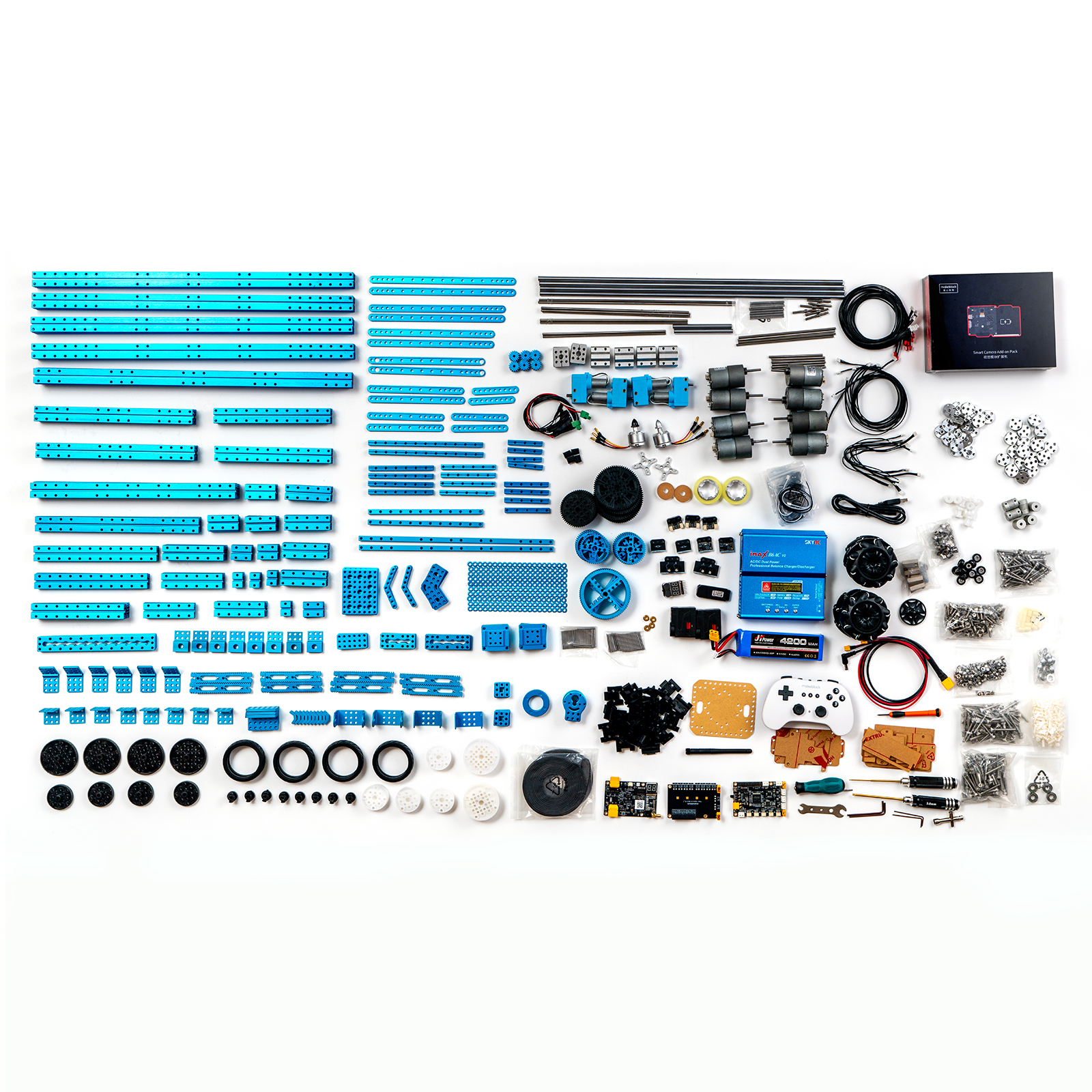
1. Basic information
| Name | 2024 MakeX Challenge Ultimate Winner Educational Competition Kit |
|---|---|
| SKU | P1090056 |
| EAN | 193122018654 |
| Package type | Paper box |
| Package size (mm) | 543×370×225 |
| Gross weight (including packaging) | 17.76 kg (39.15 lb) |
| Others | Remote control and battery included |
2. Overview
The 2024 MakeX Challenge Ultimate Winner Educational Competition Kit features:
- abundant electronic and structural parts, allowing you to build robots in more forms and ways.
- Mecanum wheels, promising agile motion of robot cars and thus facilitating the accomplishment of tasks.
- high-performance motors and servos, meeting the power needs of large robots.
3. Parts list
| Name | Quantity | Documentation |
|---|---|---|
| NovaPi | 1 | For technical information on NovaPi, see NovaPi. |
| Power expansion board | 1 | For technical information on power expansion board, see Power Extension Board (NovaPi). |
| Power management module | 1 | For technical information on power management module, see Power Management Module V2.0. |
| 180 smart encoder motor | 4 | For technical information on 180 smart encoder motor, see 180 Smart Encoder Motor. |
| DC motor-37 (200 RPM) | 4 | For technical information on DC motor-37, see DC Motor-37. |
| DC motor-37 (50 RPM) | 4 | |
| Servo MS-12A | 2 | For technical information on servo MS-12A, see Smart Servo MS-12A. |
| Brushless motor tightened clockwise | 1 | For technical information on brushless motor, see Direct-Current Brushless Motor. |
| Brushless motor tightened counterclockwise | 1 | |
| Bluetooth dongle | 1 | For the operation guide of Bluetooth dongle, see Wireless Adapter. |
| Bluetooth controller | 1 | For technical information on Bluetooth controller, see Bluetooth Controller. |
| Bluetooth module | 2 | For technical information on Bluetooth module, see Bluetooth. |
| Smart camera | 1 | For technical information on smart camera, see Smart Camera. |
| Extend module | 4 | For technical information on extend module, see Extend Module. |
| Ranging sensor | 3 | For technical information on ranging sensor, see Ranging Sensor. |
| Dual RGB color sensor | 2 | For technical information on dual RGB color sensor, see Dual RGB Color Sensor. |
| Brushless motor bracket | 2 |
- The kit uses CNC machined aluminum connecting pieces for strong structures and tight fits.
- The kit is compatible with a wide range of industry standard parts, making it perfect for various industrial applications.
For information on beams (31 types, 102 items), see Slide Beam 0824 Beam 0808 Square Beam 2424
For information on brackets (10 types, 44 items), see Brackets.
For information on linkages (8 types, 46 items), see Linkages. | | Low voltage buzzer alarm | 1 | | | Slide beam-016 | 8 | | | Slide beam-032 | 6 | | | Slide beam-048 | 8 | | | Slide beam-080 | 4 | | | Slide beam-096 | 4 | | | Slide beam-112 | 4 | | | Slide beam-144 | 4 | | | Slide beam-176 | 2 | | | Slide beam-192 | 2 | | | Slide beam-256 | 2 | | | Slide beam-320 | 4 | | | Slide Beam-496 | 4 | | | Square beam 2424-072 | 4 | | | Square beam 2424-184 | 2 | | | Square beam 2424-248 | 2 | | | Square beam 2424-504 | 4 | | | Beam-076 | 2 | | | Beam-092 | 2 | | | Beam-124 | 2 | | | Beam-156 | 2 | | | Beam-188-L2-R1 | 2 | | | Beam-204 | 2 | | | Beam-220 | 2 | | | Beam-236 | 2 | | | Square beam-056 | 4 | | | Square beam-072 | 4 | | | Square beam-088 | 4 | | | Square beam-104 | 4 | | | Square beam-184 | 2 | | | Beam 0808-184 | 2 | | | Beam 0808-312 | 2 | | | Plate 36 | 6 | | | Plate 79-B | 6 | | | Plate 45° | 6 | | | Plate 35120° | 6 | | | Plate-056 | 4 | | | Plate-072 | 4 | | | Plate-184 | 4 | | | Cuttable linkage | 10 | | | Bracket P3 | 8 | | | Bracket 33 | 8 | | | Bracket 36 | 6 | | | Bracket 33120° | 6 | | | Double gear rack 31T | 8 | | | Plastic gear 8T | 4 | | | Plastic gear 56T | 6 | | | Plastic gear 72T | 10 | | | Gear 16T | 6 | | | Gear 48T | 8 | | | Gear 80T | 4 | | | Linear motion slide unit | 4 | | | Sliding block A1 | 8 | | | Belt connector | 10 | | | DC motor-37 bracket | 8 | | | Brushless motor ESC | 2 | | | Friction wheel D4519.5 | 2 | | | Friction wheel ring D287 | 2 | | | PH2.0-2P to stripped-end cable | 8 | | | Mounting bracket | 2 | | | Rudder bracket | 2 | | | Servo-assisted shaft | 4 | | | 3S Li-Po battery | 1 | | | One-to-three power cord | 1 | | | B6AC balance charger | 1 | | | Mainboard bracket | 1 | | | NovaPi case | 1 | | | Power management module antenna | 1 | | | Wafer cable (600 mm) | 8 | | | mBuild cable (200 mm) | 8 | | | mBuild cable (600 mm) | 6 | | | USB cable | 1 | | | Track | 100 | | | Track axle 30 mm | 100 | | | Slotted screwdriver 2 mm | 1 | | | Plastic timing pulley 18T | 8 | | | Plastic timing pulley 62T | 8 | | | Plastic timing pulley 90T | 6 | | | Plastic timing pulley 62T with step | 4 | | | Plastic timing pulley 90T with step | 4 | | | Open-ended timing belt (5 m) | 2 | | | Timing pulley slice | 16 | | | Tire 68.522 mm | 4 | | | Aluminum sleeve 464 mm | 32 | | | Aluminum sleeve 466 mm | 16 | | | Roller | 32 | | | Nylon wheel | 8 | | | Threaded shaft 439 mm | 10 | | | D shaft 456 mm | 8 | | | D shaft 4160 mm | 4 | | | D shaft 4200 mm | 2 | | | D shaft 4240 mm | 2 | | | D shaft 4320 mm | 2 | | | Shaft D488 mm | 6 | | | Shaft D896 mm | 2 | | | Shaft D8496 mm | 4 | | | Shaft D4240 mm | 4 | | | Shaft clamping hub 8 mm | 6 | | | Bearing 8165 mm | 4 | | | Flange bearing 483 mm | 30 | | | Bearing F688ZZ | 6 | | | Flexible coupling 44 mm | 6 | | | Universal joint 44 mm | 2 | | | Shaft collar 4 mm | 35 | | | Shaft collar 8 mm | 10 | | | Shaft connector V3.0 | 20 | | | Shaft connector | 20 | | | Mecanum wheel 80 mm-L | 2 | | | Mecanum wheel 80 mm-R | 2 | | | Mecanum wheel coupling 80 mm | 4 | | | Mecanum wheel hub 80 mm | 4 | | | Cross screw with gasket M2.530 | 4 | | | Screw M2.512 | 4 | | | Combination screw M48 | 60 | | | Combination screw M410 | 60 | | | Combination screw M414 | 120 | | | Combination screw M416 | 120 | | | Combination screw M420 | 120 | | | Combination screw M430 | 60 | | | Combination screw M435 | 60 | | | Combination screw M440 | 60 | | | Headless screw M35 | 30 | | | Headless screw M38 | 40 | | | Flat cross screw M38 | 30 | | | Hex lock nut M3 | 40 | | | Hex nut M3 | 20 | | | Hex nut M4 | 220 | | | Hex lock nut M4 | 120 | | | Plastic rivet-R4060 | 100 | | | Plastic rivet-R4100 | 100 | | | Plastic rivet-R4120 | 100 | | | Plastic ring 472 mm | 50 | | | Plastic ring 473 mm | 30 | | | Plastic ring 4710 mm | 20 | | | Screwdriver 1.5 mm | 1 | | | Screwdriver 3 mm | 1 | | | Wrench 5 mm & 7 mm | 1 | | | Screwdriver hex 2.5 mm & cross | 1 | | | Small four-way socket wrench | 1 | | | Hex key 2.5 mm | 2 | | | Hex key 1.5 mm | 2 | | | Support for power management module | 1 | | | Stiffener 1616-008-M4 | 10 | |
4. About the competition
MakeX is an international robotics competition and education platform that promotes multidisciplinary learning within the fields of science and technology. It aims at building a world where STEAM education is highly appreciated and where young people are passionate about innovation by engaging them in activities such as exciting robotics competitions, STEAM carnivals, tech events, and educational conferences.
MakeX Challenge is a highly competitive event for high school and vocational school students aged 11-18 years. This event, with its simple and easy-to-understand rules, offers an exciting spectacle and enriches the overall experience of participants. Through the design, construction, and programming of large robots, the contestants enhance their design and multi-dimensional thinking skills. Additionally, the event encourages the development of logical thinking, strategic analysis, teamwork, and decision-making abilities.
 To view information about registration, entry requirements, and available competitions, visit www.makex.cc/en or contact us by email: makex_overseas@makeblock.com (overseas)
makex@makeblock.com (China)
To view information about registration, entry requirements, and available competitions, visit www.makex.cc/en or contact us by email: makex_overseas@makeblock.com (overseas)
makex@makeblock.com (China)
5. More information
Getting Started with the 2024 MakeX Challenge Ultimate Winner Educational Competition Kit Introduction to the 2024 MakeX Competitions and Kits mBlock 5 Online Help
Getting Started with the 2024 MakeX Challenge Ultimate Winner Educational Competition Kit
 Thank you for choosing the 2024 MakeX Challenge Ultimate Winner Educational Competition Kit. If you are using this kit for the first time, we recommend that you read these instructions carefully to get the most out of it.
1. Unpack and check
Make sure the following parts are included in the kit. If there is any missing part, contact our after-sales service or distributors.
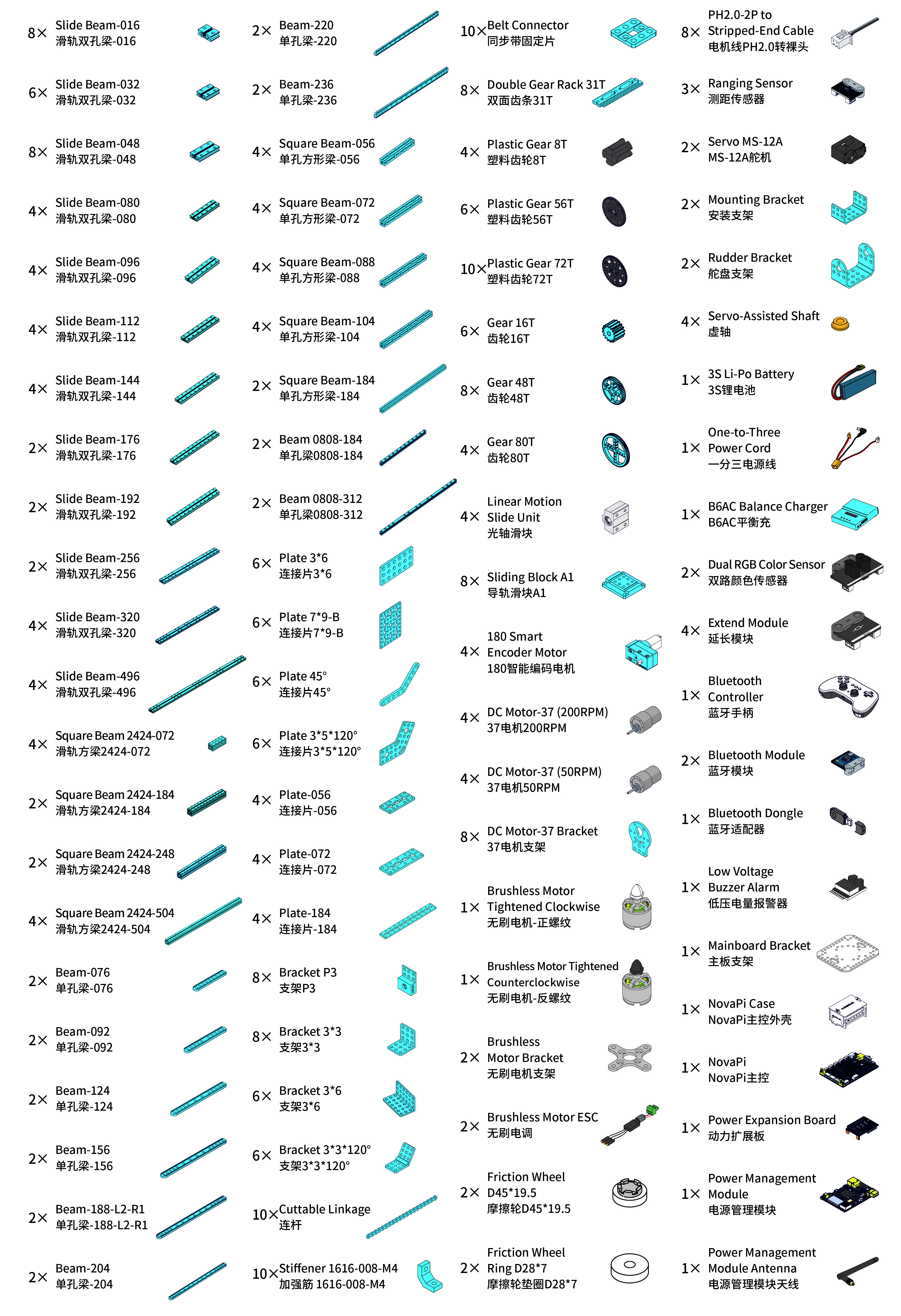
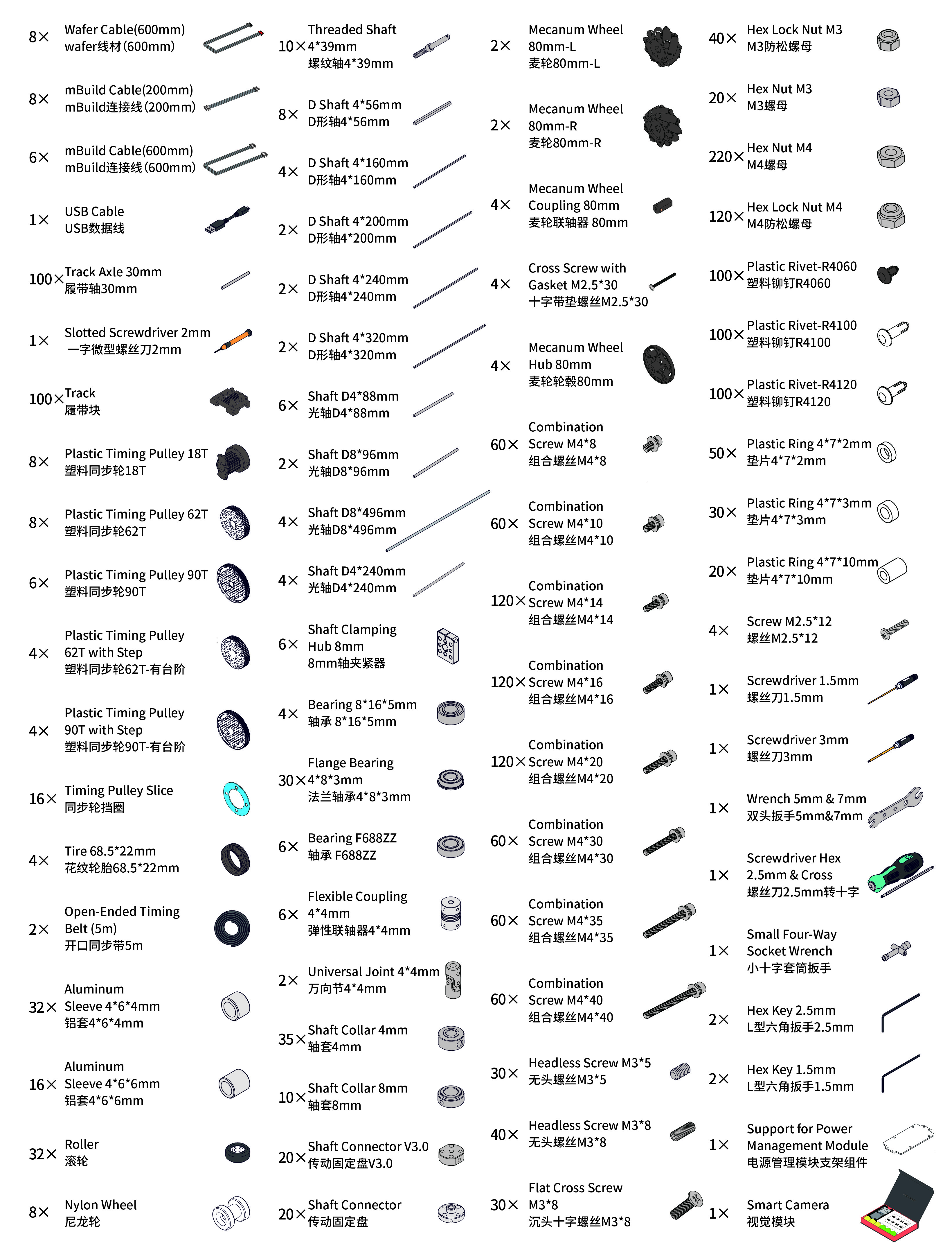 :::warning
Note: Keep the parts properly after each use so that you can reuse them in other projects.
:::warning
Note: Keep the parts properly after each use so that you can reuse them in other projects.
:::
2. Learn about the main components
The kit includes a main control board named NovaPi, a power expansion board and a power management module. The power management module can work with the MakeboX to monitor the progress of this event. NovaPi and the power expansion board work together to power and control other electronic parts, including encoder motors, DC motors, servos, and sensors.
| Name | Quantity | Documentation |
|---|---|---|
| NovaPi | 1 | For technical information on NovaPi, see NovaPi. |
| Power expansion board | 1 | For technical information on power expansion board, see Power Extension Board (NovaPi). |
| Power management module | 1 | For technical information on power management module, see Power Management Module V2.0. |
| 180 smart encoder motor | 4 | For technical information on 180 smart encoder motor, see 180 Smart Encoder Motor. |
| DC motor-37 (200 RPM) | 4 | For technical information on DC motor-37, see DC Motor-37. |
| DC motor-37 (50 RPM) | 4 | |
| Servo MS-12A | 1 | For technical information on servo MS-12A, see Smart Servo MS-12A. |
| Brushless motor tightened clockwise | 1 | For technical information on brushless motor, see Direct-Current Brushless Motor. |
| Brushless motor tightened counterclockwise | 1 | |
| Bluetooth dongle | 1 | For the operation guide of Bluetooth dongle, see Wireless Adapter. |
| Bluetooth controller | 1 | For technical information on Bluetooth controller, see Bluetooth Controller. |
| Bluetooth module | 2 | For technical information on Bluetooth module, see Bluetooth. |
| Smart camera | 1 | For technical information on smart camera, see Smart Camera. |
| Extend module | 4 | For technical information on extend module, see Extend Module. |
| Ranging sensor | 3 | For technical information on ranging sensor, see Ranging Sensor. |
| Dual RGB color sensor | 2 | For technical information on dual RGB color sensor, see Dual RGB Color Sensor. |
Simple chassis assembly
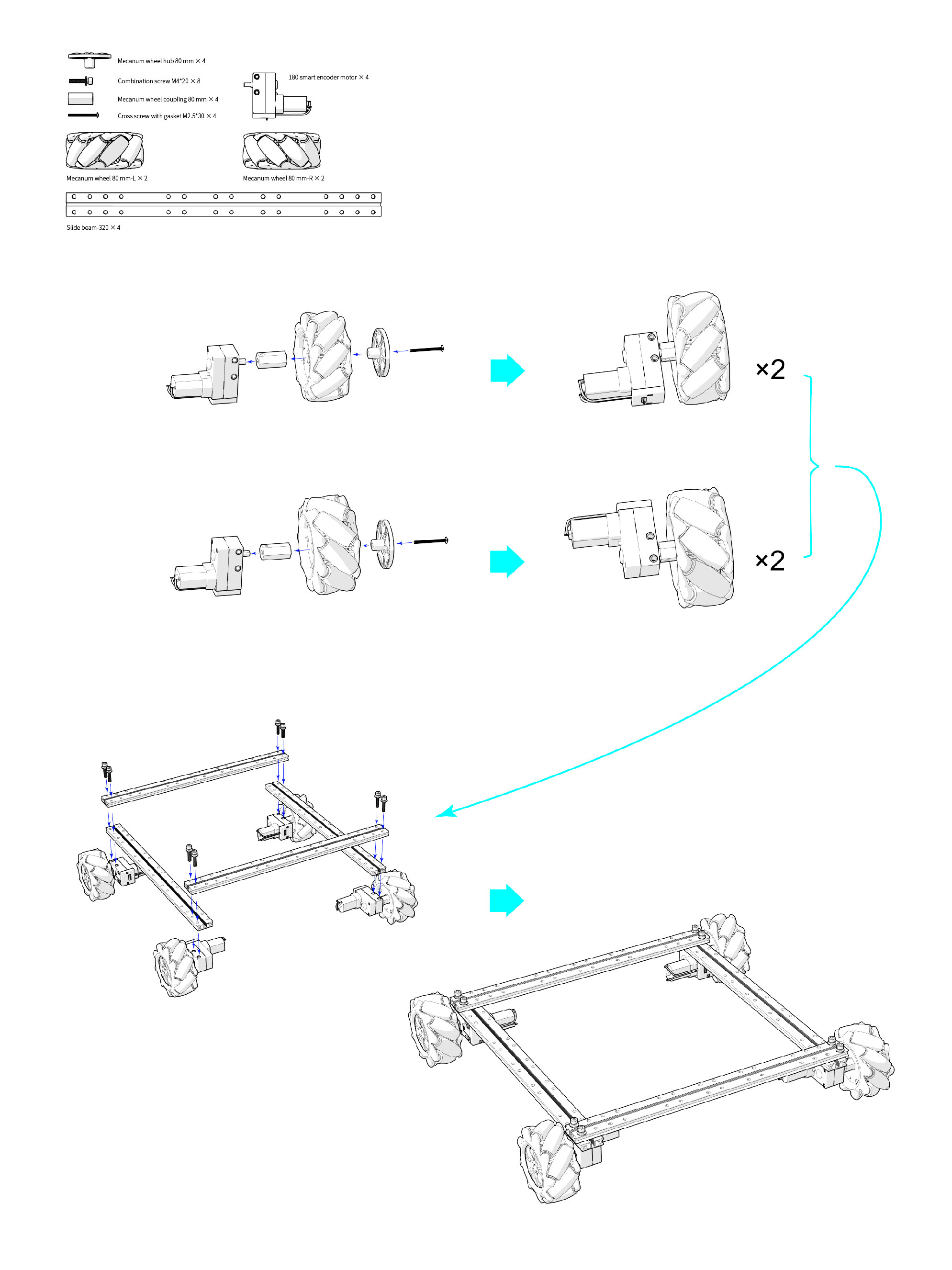
3. Explore beyond
3.1 Programming
You can use the parts to build your own robot and program it using mBlock 5 to bring your ideas to life.
3.2 Get more hardware
There is a wide range of peripherals that can be added to the kit to bring your ideas to life. Contact us if you want to take them home.
4. About the competition
MakeX is an international robotics competition and education platform that promotes multidisciplinary learning within the fields of science and technology. It aims at building a world where STEAM education is highly appreciated and where young people are passionate about innovation by engaging them in activities such as exciting robotics competitions, STEAM carnivals, tech events, and educational conferences.
MakeX Challenge is a highly competitive event for high school and vocational school students aged 11-18 years. This event, with its simple and easy-to-understand rules, offers an exciting spectacle and enriches the overall experience of participants. Through the design, construction, and programming of large robots, the contestants enhance their design and multi-dimensional thinking skills. Additionally, the event encourages the development of logical thinking, strategic analysis, teamwork, and decision-making abilities.
 To view information about registration, entry requirements, and available competitions, visit www.makex.cc/en or contact us by email: makex_overseas@makeblock.com (overseas)
makex@makeblock.com (China)
To view information about registration, entry requirements, and available competitions, visit www.makex.cc/en or contact us by email: makex_overseas@makeblock.com (overseas)
makex@makeblock.com (China)
5. Online support
If you encounter any product quality issues or find any parts missing when you open the package, contact us for after-sales services at support@makeblock.com.
We would also appreciate it if you could give us your feedback on the product at cyber.list@makeblock.com.
6. More information
Introduction to the 2024 MakeX Challenge Ultimate Winner Educational Competition Kit Introduction to the 2024 MakeX Competitions and Kits mBlock 5 Online Help
Introduction to the 2024 MakeX Challenge Upgrade Kit

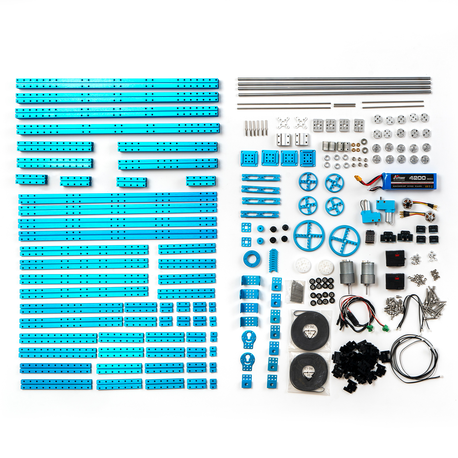
1. Basic information
| Name | 2024 MakeX Challenge Upgrade Kit |
|---|---|
| SKU | P1090057 |
| EAN | 193122018661 |
| Package type | Paper box |
| Package size (mm) | 543×150×140 (blue parts) |
| 298×203×118 (other parts) | |
| Gross weight (including packaging) | 8.3 kg (18.3 lb) |
| Others | Battery included, remote control not included |
2. Overview
The 2024 MakeX Challenge Upgrade Kit can work with the 2022 MakeX Challenge Educational Competition Kit. Together, they constitute the 2024 MakeX Challenge Ultimate Winner Educational Competition Kit. This upgrade kit is suitable for those who want to customize their kit for the 2024 MakeX Challenge competition.
For more information, see Introduction to the 2024 MakeX Challenge Ultimate Winner Educational Competition Kit.
3. Parts list
| Name | Quantity | Documentation |
|---|---|---|
| 180 smart encoder motor | 2 | For technical information on 180 smart encoder motor, see 180 Smart Encoder Motor. |
| DC motor-37 (200 RPM) | 1 | For technical information on DC motor-37, see DC Motor-37. |
| DC motor-37 (50 RPM) | 1 | |
| Servo MS-12A | 2 | For technical information on servo MS-12A, see Smart Servo MS-12A. |
| Brushless motor tightened clockwise | 1 | For technical information on brushless motor, see Direct-Current Brushless Motor. |
| Brushless motor tightened counterclockwise | 1 | |
| Extend module | 4 | For technical information on extend module, see Extend Module. |
| Dual RGB color sensor | 2 | For technical information on dual RGB color sensor, see Dual RGB Color Sensor. |
| Slide beam-016 | 6 |
- The kit uses CNC machined aluminum connecting pieces for strong structures and tight fits.
- The kit is compatible with a wide range of industry standard parts, making it perfect for various industrial applications.
For information on beams (16 types, 54 items), see Slide Beam 0824 Beam 0808 Square Beam 2424
For information on brackets (5 types, 16 items), see Brackets. | | Slide beam-032 | 6 | | | Slide beam-048 | 4 | | | Slide beam-080 | 2 | | | Slide beam-096 | 2 | | | Slide beam-112 | 4 | | | Slide beam-144 | 4 | | | Slide beam-176 | 2 | | | Slide beam-192 | 2 | | | Slide beam-256 | 2 | | | Slide beam-320 | 4 | | | Slide beam-496 | 4 | | | Square beam 2424-072 | 4 | | | Square beam 2424-184 | 2 | | | Square beam 2424-248 | 2 | | | Square beam 2424-504 | 4 | | | Bracket P3 | 8 | | | Mounting bracket | 2 | | | Rudder bracket | 2 | | | DC motor-37 bracket | 2 | | | Brushless motor bracket | 2 | | | Brushless motor ESC | 2 | | | Track | 50 | | | Track axle 30 mm | 50 | | | Servo-assisted shaft | 4 | | | Threaded shaft 439 mm | 6 | | | Low voltage buzzer alarm | 1 | | | Stiffener 1616-008-M4 | 10 | | | 3S Li-Po battery | 1 | | | Double gear rack 31T | 4 | | | Gear 16T | 2 | | | Gear 48T | 4 | | | Gear 80T | 2 | | | Roller | 16 | | | Plastic timing pulley 18T | 4 | | | Plastic timing pulley 62T | 2 | | | Timing pulley slice | 16 | | | Belt connector | 2 | | | Open-ended timing belt (5 m) | 2 | | | Aluminum sleeve 464 mm | 16 | | | Aluminum sleeve 466 mm | 8 | | | Linear motion slide unit | 2 | | | Sliding block A1 | 4 | | | mBuild cable (200 mm) | 4 | | | mBuild cable (600 mm) | 3 | | | D shaft 456 mm | 2 | | | D shaft 4160 mm | 2 | | | Shaft D8496 mm | 4 | | | Shaft D4240 mm | 2 | | | Shaft clamping hub 8 mm | 4 | | | Bearing F688ZZ | 2 | | | Flexible coupling 44 mm | 4 | | | Shaft collar 4 mm | 6 | | | Shaft collar 8 mm | 6 | | | Shaft connector V3.0 | 10 | | | Shaft connector | 10 | | | Combination screw M48 | 30 | | | Combination screw M410 | 30 | | | Combination screw M414 | 30 | | | Combination screw M416 | 30 | | | Combination screw M420 | 30 | | | Combination screw M430 | 30 | | | Combination screw M435 | 30 | | | Combination screw M440 | 30 | | | Headless screw M35 | 20 | | | Headless screw M38 | 20 | | | Flat cross screw M3*8 | 20 | | | Hex lock nut M3 | 20 | | | Hex nut M3 | 20 | | | Hex nut M4 | 20 | | | Hex lock nut M4 | 20 | |
4. About the competition
MakeX is an international robotics competition and education platform that promotes multidisciplinary learning within the fields of science and technology. It aims at building a world where STEAM education is highly appreciated and where young people are passionate about innovation by engaging them in activities such as exciting robotics competitions, STEAM carnivals, tech events, and educational conferences.
MakeX Challenge is a highly competitive event for high school and vocational school students aged 11-18 years. This event, with its simple and easy-to-understand rules, offers an exciting spectacle and enriches the overall experience of participants. Through the design, construction, and programming of large robots, the contestants enhance their design and multi-dimensional thinking skills. Additionally, the event encourages the development of logical thinking, strategic analysis, teamwork, and decision-making abilities.
 To view information about registration, entry requirements, and available competitions, visit www.makex.cc/en or contact us by email: makex_overseas@makeblock.com (overseas)
makex@makeblock.com (China)
To view information about registration, entry requirements, and available competitions, visit www.makex.cc/en or contact us by email: makex_overseas@makeblock.com (overseas)
makex@makeblock.com (China)
5. More information
Introduction to the 2024 MakeX Competitions and Kits Getting Started with the 2024 MakeX Challenge Upgrade Kit Introduction to the 2024 MakeX Challenge Ultimate Winner Educational Competition Kit Getting Started with the 2024 MakeX Challenge Ultimate Winner Educational Competition Kit mBlock 5 Online Help
Getting Started with the 2024 MakeX Challenge Upgrade Kit
 Thank you for choosing the 2024 MakeX Challenge Upgrade Kit. If you are using this pack for the first time, we recommend that you read these instructions carefully to get the most out of it.
1. Unpack and check
Make sure the following parts are included in the kit. If there is any missing part, contact our after-sales service or distributors.
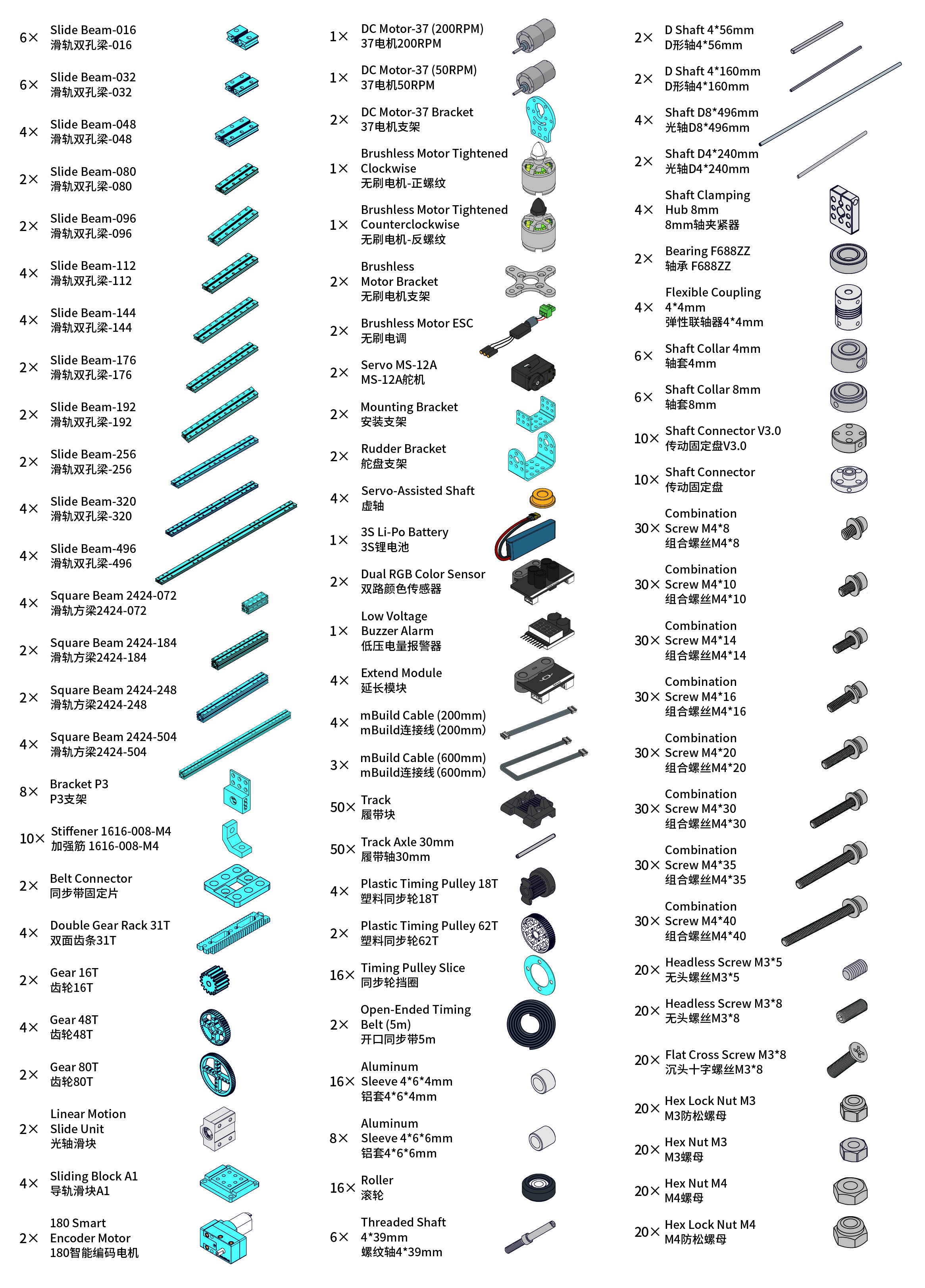 :::warning
Note: Keep the parts properly after each use so that you can reuse them in other projects.
:::warning
Note: Keep the parts properly after each use so that you can reuse them in other projects.
:::
2. Learn about the main components
| Name | Quantity | Documentation |
|---|---|---|
| 180 smart encoder motor | 2 | For technical information on 180 smart encoder motor, see 180 Smart Encoder Motor. |
| DC motor-37 (200 RPM) | 1 | For technical information on DC motor-37, see DC Motor-37. |
| DC motor-37 (50 RPM) | 1 | |
| Brushless motor tightened clockwise | 1 | For technical information on brushless motor, see Direct-Current Brushless Motor. |
| Brushless motor tightened counterclockwise | 1 | |
| Servo MS-12A | 2 | For technical information on servo MS-12A, see Smart Servo MS-12A. |
| Extend module | 4 | For technical information on extend module, see Extend Module. |
| Dual RGB color sensor | 2 | For technical information on dual RGB color sensor, see Dual RGB Color Sensor. |
3. Explore beyond
3.1 Programming
You can use the parts to build your own robot and program it using mBlock 5 to bring your ideas to life.
3.2 Get more hardware
There is a wide range of peripherals that can be added to the kit to bring your ideas to life. Contact us if you want to take them home.
4. About the competition
MakeX is an international robotics competition and education platform that promotes multidisciplinary learning within the fields of science and technology. It aims at building a world where STEAM education is highly appreciated and where young people are passionate about innovation by engaging them in activities such as exciting robotics competitions, STEAM carnivals, tech events, and educational conferences.
MakeX Challenge is a highly competitive event for high school and vocational school students aged 11-18 years. This event, with its simple and easy-to-understand rules, offers an exciting spectacle and enriches the overall experience of participants. Through the design, construction, and programming of large robots, the contestants enhance their design and multi-dimensional thinking skills. Additionally, the event encourages the development of logical thinking, strategic analysis, teamwork, and decision-making abilities.
 To view information about registration, entry requirements, and available competitions, visit www.makex.cc/en or contact us by email: makex_overseas@makeblock.com (overseas)
makex@makeblock.com (China)
To view information about registration, entry requirements, and available competitions, visit www.makex.cc/en or contact us by email: makex_overseas@makeblock.com (overseas)
makex@makeblock.com (China)
5. Online support
If you encounter any product quality issues or find any parts missing when you open the package, contact us for after-sales services at support@makeblock.com.
We would also appreciate it if you could give us your feedback on the product at cyber.list@makeblock.com.
6. More information
Introduction to the 2024 MakeX Competitions and Kits Introduction to the 2024 MakeX Challenge Upgrade Kit Introduction to the 2024 MakeX Challenge Ultimate Winner Educational Competition Kit Getting Started with the 2024 MakeX Challenge Ultimate Winner Educational Competition Kit mBlock 5 Online Help
Introduction to the 2024 MakeX Challenge Ultimate Winner Arena and Frame
 The kit does not include the MakeboX.
1. Basic information
| Name | 2024 MakeX Challenge Ultimate Winner Arena and Frame |
|---|---|
| SKU | P1090058 |
| EAN | 193122018630 |
| Package type | Paper box |
| Package size (mm) | 100×100×1580 (map) |
| 990×530×20 (metal net) | |
| 380×180×180 (hanging basket) | |
| 670×390×260 (bottles) | |
| 1000×290×120 (flat beams) | |
| 305×298×203 (flat beam locks) | |
| 1040×370×265 (other parts-1) | |
| 1000×290×120 (other parts-2) | |
| 864×442×175 (other parts-3) | |
| 1062×526×155 (other parts-4) | |
| 1030×75×78 (other parts-5) | |
| Gross weight (including packaging) | 155.22 kg (342.2 lb) |
| Others | Remote control and battery not included |
2. Overview
If this is your first MakeX Challenge competition, or if you would like to purchase a complete package for practice or hosting a MakeX competition, purchase the** 2024 MakeX Challenge Ultimate Winner Arena and Frame**.
3. Parts list
| Name | Quantity |
|---|---|
| Flat beam 160 | 92 |
| Flat beam 220 | 24 |
| Flat beam 293 | 18 |
| Flat beam 960 | 56 |
| Octagonal pillar-45 | 24 |
| Octagonal pillar-250 | 16 |
| Octagonal pillar-400 | 4 |
| Octagonal pillar-960 | 28 |
| Flat beam lock | 380 |
| Octagonal pillar cover | 144 |
| Flat beam cover | 4 |
| Polygonal board A | 2 |
| Polygonal board B | 2 |
| Short board A | 4 |
| Short board B | 12 |
| Short board C | 2 |
| Short board D | 10 |
| Short board E | 10 |
| Short board F | 12 |
| Long board A | 6 |
| Long board B | 4 |
| Long board C | 6 |
| Long board D | 4 |
| Long board E | 2 |
| Long board F | 2 |
| Long board G | 8 |
| Long board H | 2 |
| MakeX board blue & black | 8 |
| MakeX board red & black | 8 |
| MakeX sticker red/blue | 6 |
| Metal net | 4 |
| Hanging basket | 4 |
| Plate A | 12 |
| Plate B | 2 |
| Square beam 0808-056 | 12 |
| Beam 0808-024 | 6 |
| Beam 0412-036 | 12 |
| Beam 0412-092 | 12 |
| Slide beam 0824-144 | 6 |
| Hinge | 12 |
| Coil spring | 12 |
| Wheel | 4 |
| Screw M3*6 | 4 |
| Screw M4*8 | 64 |
| Screw M4*10 | 40 |
| Screw M4*16 | 60 |
| Screw M4*22 | 80 |
| Rectangular nut M4 | 32 |
| Hex lock nut M4 | 150 |
| Hex stud M4*32 | 16 |
| Plastic ring 472 mm | 18 |
| Plastic ring 473 mm | 25 |
| Shaft collar | 4 |
| Flange bearing | 24 |
| Map | 1 |
| Double-sided fabric tape | 1 |
| Transparent tape | 1 |
| 3M double-sided nano tape | 1 |
| Bottle blue & black | 12 |
| Bottle red & black | 12 |
| Yellow cube | 6 |
| Cube sticker A | 5 |
| Cube sticker B | 2 |
| Yellow cone | 6 |
| MakeX blue disc | 37 |
| MakeX red disc | 37 |
| Hex Allen key T30 | 3 |
| Screwdriver hex 2.5 mm & cross | 2 |
| Hex key 1.5 mm | 2 |
| Hex key 2.5 mm | 2 |
| Wrench 5 mm & 7 mm | 2 |
4. Assembly instructions
After checking the number of parts, refer to the following document to assemble the 2024 MakeX Challenge Ultimate Winner Arena. 2024 MakeX Challenge Ultimate Winner Arena Assembly Instructions.pdf
5. More information
Introduction to the 2024 MakeX Challenge Ultimate Winner Educational Competition Kit Getting Started with the 2024 MakeX Challenge Ultimate Winner Educational Competition Kit Introduction to the 2024 MakeX Competitions and Kits mBlock 5 Online Help
Introduction to the 2024 MakeX Challenge Arena Upgrade Kit - Energy Innovator
 This kit does not include the MakeboX.
1. Basic information
| Name | 2024 MakeX Challenge Arena Upgrade Kit - Energy Innovator |
|---|---|
| SKU | P1090059 |
| EAN | 193122018647 |
| Package type | Paper box |
| Package size (mm) | 100×100×1580 (map) |
| 305×196×203 (flat beam locks) | |
| 380×180×180 (hanging basket) | |
| 365×3550×3100 (other parts-1) | |
| 1040×370×265 (other parts-2) | |
| 1030×75×78 (other parts-3) | |
| Gross weight (including packaging) | 88.04 kg (194.09 lb) |
| Others | Remote control and battery not included |
2. Overview
This kit is designed for users with the 2022 MakeX Challenge Energy Innovator Kit. With this kit, they can participate in the 2024 competition.
3. Parts list
Make sure the following parts are included in the kit. If there is any missing part, contact our after-sales service or distributors.
| Name | Quantity |
|---|---|
| Flat beam 160 | 70 |
| Flat beam 220 | 14 |
| Flat beam 293 | 18 |
| Flat beam 960 | 14 |
| Octagonal pillar-45 | 24 |
| Octagonal pillar-250 | 12 |
| Octagonal pillar-960 | 16 |
| Flat beam lock | 250 |
| Octagonal pillar cover | 116 |
| Polygonal board A | 2 |
| Polygonal board B | 2 |
| Short board A | 4 |
| Short board B | 12 |
| Short board C | 2 |
| Short board D | 10 |
| Short board E | 10 |
| Short board F | 12 |
| Long board A | 6 |
| Long board B | 4 |
| Long board C | 6 |
| Long board D | 4 |
| Long board E | 2 |
| Long board F | 2 |
| Long board G | 8 |
| Long board H | 2 |
| MakeX board blue & black | 1 |
| MakeX board red & black | 1 |
| MakeX sticker red/blue | 6 |
| Hanging basket | 2 |
| Plate A | 12 |
| Plate B | 2 |
| Square beam 0808-056 | 12 |
| Beam 0808-024 | 6 |
| Beam 0412-036 | 12 |
| Beam 0412-092 | 12 |
| Slide beam 0824-144 | 6 |
| Hinge | 12 |
| Coil spring | 12 |
| Wheel | 4 |
| Screw M3*6 | 4 |
| Screw M4*8 | 64 |
| Screw M4*10 | 40 |
| Screw M4*16 | 60 |
| Screw M4*22 | 80 |
| Rectangular nut M4 | 32 |
| Hex lock nut M4 | 150 |
| Hex stud M4*32 | 16 |
| Plastic ring 472 mm | 18 |
| Plastic ring 473 mm | 25 |
| Shaft collar | 4 |
| Flange bearing | 24 |
| Map | 1 |
| Double-sided fabric tape | 1 |
| Transparent tape | 1 |
| 3M double-sided nano tape | 1 |
| Yellow cone | 6 |
| MakeX blue disc | 37 |
| MakeX red disc | 37 |
| Hex Allen key T30 | 1 |
| Screwdriver hex 2.5 mm & cross | 1 |
| Hex key 1.5 mm | 1 |
| Hex key 2.5 mm | 1 |
| Wrench 5 mm & 7 mm | 1 |
4. Assembly instructions
After checking the number of parts, refer to the following document to assemble the 2024 MakeX Challenge Ultimate Winner Arena. 2024 MakeX Challenge Ultimate Winner Arena Assembly Instructions.pdf
5. More information
Introduction to the 2024 MakeX Challenge Ultimate Winner Educational Competition Kit Getting Started with the 2024 MakeX Challenge Ultimate Winner Educational Competition Kit Introduction to the 2024 MakeX Challenge Ultimate Winner Arena and Frame Introduction to the 2024 MakeX Competitions and Kits mBlock 5 Online Help
Introduction to the CyberPi Educational Competition Kit
1. Basic information
| Name | CyberPi Educational Competition Kit |
|---|---|
| SKU | P1030137 |
| Package type | Paper box |
| Package size (mm) | 302×232×54 |
| Gross weight (including packaging) | 0.84 kg (1.85 lb) |
| Others | Battery included, remote control not included |
2. Overview
The CyberPi Educational Competition Kit is developed based on the K12 curriculum and includes cutting-edge knowledge and applied learning of engineering, data science, AI, and IoT. The kit is recommended for the 2024 MakeX Spark competition.
3. Parts list
| Name | Quantity | Documentation |
|---|---|---|
| CyberPi | 1 | For technical information on CyberPi, see CyberPi. |
| For the operation guide of CyberPi, see CyberPi Operation Guide. | ||
| Pocket shield | 1 | For technical information on pocket shield, see Pocket Shield. |
| Servo MS-1.5A | 1 | For technical information on servo MS-1.5A, see Servo MS-1.5A. |
| Ranging sensor | 1 | For technical information on ranging sensor, see Ranging Sensor. |
| Multi-touch sensor | 1 | For technical information on multi-touch sensor, see Multi-touch Sensor. |
| Angle sensor | 1 | For technical information on angle sensor, see Angle Sensor. |
| Fan | 1 | For technical information on fan, see Fan. |
| Dual shaft TT motor | 1 | For technical information on dual shaft TT motor, see Dual-Shaft TT Motor. |
| LED strip (1 m) | 1 | For technical information on LED strip, see LED Strip (0.5 m and 1 m). |
| Bracket 3*3 | 2 |
- The kit uses CNC machined aluminum connecting pieces for strong structures and tight fits.
- The kit is compatible with a wide range of industry standard parts, making it perfect for various industrial applications.
- The kit includes materials commonly used in creative projects, such as wooden board and cardboard. | | Plate 36 | 2 | | | Axle 31 mm | 2 | | | Axle 100 mm | 1 | | | Coupling | 2 | | | Plastic wheel | 4 | | | Rubber band | 5 | | | Transfer pin | 6 | | | Plastic rivet-R4060 | 10 | | | Plastic rivet-R4120 | 4 | | | Screw M414 | 4 | | | Screw M422 | 5 | | | Screw M435 | 4 | | | Hex nut M4 | 14 | | | Screwdriver hex 2.5 mm & cross | 1 | | | Wrench 5 mm & 7 mm | 1 | | | Motor cable | 1 | | | mBuild cable (100 mm) | 2 | | | mBuild cable (200 mm) | 3 | | | USB cable (Type-C) | 1 | | | Board 01 | 1 | | | Board 02 | 1 | | | Cardboard | 1 | |
4. Project showcase
Self-driving car
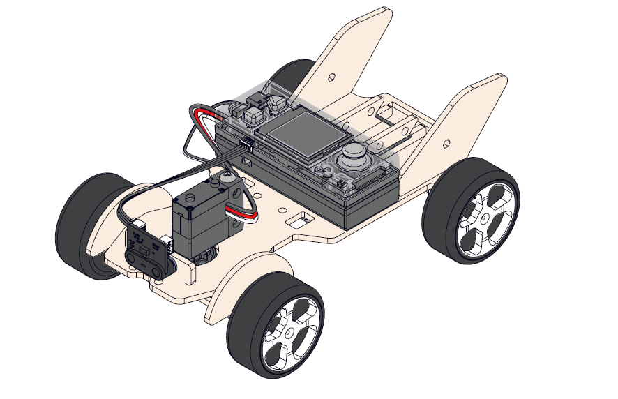
Smart trash can
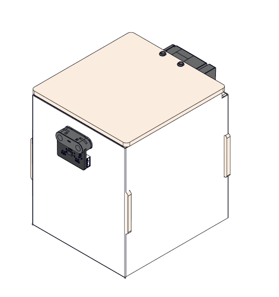
Head-shaking fan
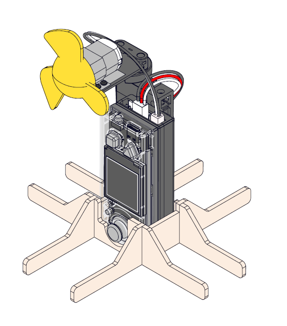
5. About the competition
MakeX is an international robotics competition and education platform that promotes multidisciplinary learning within the fields of science and technology. It aims at building a world where STEAM education is highly appreciated and where young people are passionate about innovation by engaging them in activities such as exciting robotics competitions, STEAM carnivals, tech events, and educational conferences.
MakeX Spark is a creative event for young people aged 6-13 years. It comes in two forms: online event and onsite event. Contestants are encouraged to use a variety of materials to design and build their projects. Through project-based learning, contestants enhance their imagination and creativity; through critical thinking and real-world problem research, they improve their cross-disciplinary problem-solving skills. Also, contestants' expression and teamwork skills can be enhanced through project demonstration.
 To view information about registration, entry requirements, and available competitions, visit www.makex.cc/en or contact us by email: makex_overseas@makeblock.com (overseas)
makex@makeblock.com (China)
To view information about registration, entry requirements, and available competitions, visit www.makex.cc/en or contact us by email: makex_overseas@makeblock.com (overseas)
makex@makeblock.com (China)
6. More information
Getting Started with the CyberPi Educational Competition Kit Introduction to the 2024 MakeX Competitions and Kits mBlock 5 Online Help
Getting Started with the CyberPi Educational Competition Kit
Thank you for choosing CyberPi Educational Competition Kit. If you are using this kit for the first time, we recommend that you read this guide carefully to get the most out of it.
1. Unpack and check
Make sure the following parts are included in the kit. If there is any missing part, contact our after-sales service or distributors.
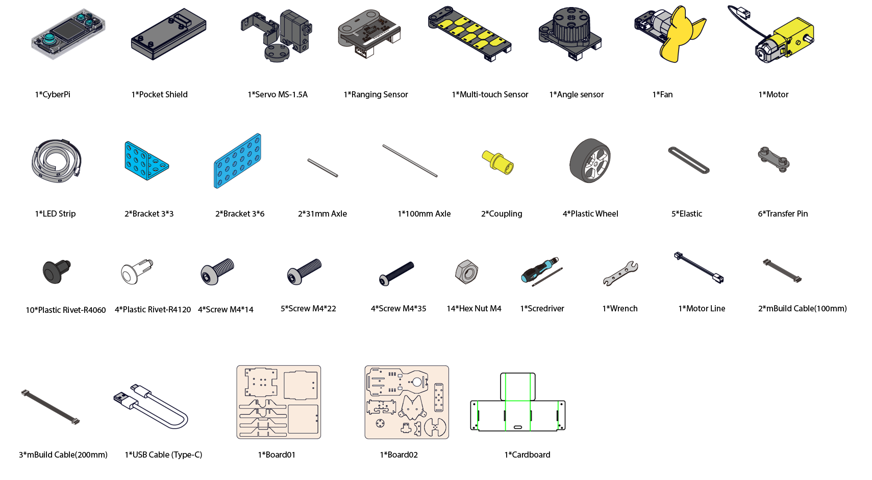
2. Learn about the main components
| Name | Quantity | Documentation |
|---|---|---|
| CyberPi | 1 | For technical information on CyberPi, see CyberPi. |
| For the operation guide of CyberPi, see CyberPi Operation Guide. | ||
| Pocket shield | 1 | For technical information on pocket shield, see Pocket Shield. |
| Servo MS-1.5A | 1 | For technical information on servo MS-1.5A, see Servo MS-1.5A. |
| Ranging sensor | 1 | For technical information on ranging sensor, see Ranging Sensor. |
| Multi-touch sensor | 1 | For technical information on multi-touch sensor, see Multi-touch Sensor. |
| Angle sensor | 1 | For technical information on angle sensor, see Angle Sensor. |
| Fan | 1 | For technical information on fan, see Fan. |
| Dual shaft TT motor | 1 | For technical information on dual shaft TT motor, see Dual-Shaft TT Motor. |
| LED strip (1 m) | 1 | For technical information on LED strip, see LED Strip (0.5 m and 1 m). |
3. Explore beyond
There is a wide range of peripherals that can be added to CyberPi to bring your ideas to life. Contact us if you want to take them home.
You can also find more technical information from our CyberPi Series User Manual.
4. About the competition
MakeX is an international robotics competition and education platform that promotes multidisciplinary learning within the fields of science and technology. It aims at building a world where STEAM education is highly appreciated and where young people are passionate about innovation by engaging them in activities such as exciting robotics competitions, STEAM carnivals, tech events, and educational conferences.
MakeX Spark is a creative event for young people aged 6-13 years. It comes in two forms: online event and onsite event. Contestants are encouraged to use a variety of materials to design and build their projects. Through project-based learning, contestants enhance their imagination and creativity; through critical thinking and real-world problem research, they improve their cross-disciplinary problem-solving skills. Also, contestants' expression and teamwork skills can be enhanced through project demonstration.
 To view information about registration, entry requirements, and available competitions, visit www.makex.cc/en or contact us by email: makex_overseas@makeblock.com (overseas)
makex@makeblock.com (China)
To view information about registration, entry requirements, and available competitions, visit www.makex.cc/en or contact us by email: makex_overseas@makeblock.com (overseas)
makex@makeblock.com (China)
5. Online support
If you encounter any product quality issues or find any parts missing when you open the package, contact us for after-sales services at support@makeblock.com.
We would also appreciate it if you could give us your feedback on the product at cyber.list@makeblock.com.
6. More information
Introduction to the CyberPi Educational Competition Kit Introduction to the 2024 MakeX Competitions and Kits mBlock 5 Online Help mBot2 Operation Guide CyberPi Operation Guide mBlock-Python Editor Online Help Python API Documentation for CyberPi
Getting started with the CyberPi Educational Competition Kit
1. Foreword
Thank you for choosing CyberPi Educational Competition Kit, an upgraded version of CyberPi AI & IoT Innovation kit. If you are using this kit for the first time, we recommend that you read this guide carefully to get the most out of it.
2. Unpacking and check
Make sure the following parts are included in the kit. If there is any missing part, contact our after-sales service or distributors.
3. Learn about the main components
This kit contains a variety of electronic and structural parts that you can get to know as you go through the course.
You can also familiarize yourself with these parts before you start the course to quickly get into the swing of things.
| Name | Quantity | Documentation |
|---|---|---|
| CyberPi | 1 | For technical information on CyberPi, see makeblock.com/en/docs/cyberpi/cyberpi |
| For the operation guide of CyberPi, see | ||
| makeblock.com/en/docs/cyberpi/cyberpi-start | ||
| Pocket Shield | 1 | For technical information on Pocket Shield, see |
| makeblock.com/en/docs/cyberpi/pocket-shield | ||
| Servo MS-1.5A | 1 | For technical information on Servo MS-1.5A, see http://docs.makeblock.com/diy-platform/en/electronic-modules/motors/meds15-servo-motor.html |
| Ranging Sensor | 1 | For technical information on Ranging Sensor, see |
| makeblock.com/en/docs/cyberpi/ranging_sensor | ||
| Multi-touch Sensor | 1 | For technical information on Multi-touch Sensor, see |
| makeblock.com/en/docs/cyberpi/multi_touch | ||
| Angle sensor | 1 | For technical information on Angle sensor, see |
| makeblock.com/en/docs/cyberpi/angle_sensor | ||
| Fan | 1 | For technical information on Fan, see |
| makeblock.com/en/docs/cyberpi/fan-package | ||
| Dual Shaft TT Motor | 1 | For technical information on Dual Shaft TT Motor, see |
| makeblock.com/en/docs/cyberpi/tt-dual-shaft | ||
| LED Strip(1m) | 1 | For technical information on LED Strip(1m), see |
| makeblock.com/en/docs/cyberpi/led-strip |
4. Courses
Documents are on the way. Stay tuned!
5. Explore beyond
CyberPi has a wide range of peripherals to bring your ideas to life. Contact us (https://education.makeblock.com/contact-us) if you want to take them home.
6. About the competition
MakeX is an international robotics competition and education platform that promotes multidisciplinary learning within the fields of science and technology. It aims at building a world where STEAM education is highly appreciated and where young people are passionate about innovation by engaging them in exciting Robotics Competition, STEAM Carnival, Tech Event, Educational Conference etc.
MakeX Spark is an innovation competition program for young people aged 6-13.
The competition includes online and onsite competition formats. Contestants are encouraged to use a variety of materials to design and build their projects. Through project-based learning, contestants boost their imagination and creativity, and combined with critical thinking and research of a real-world issue, contestants are improving their cross-disciplinary problem-solving skills. Also, the contestants' skills in expression, collaboration, and cooperation can be enhanced through project demonstration.
To view information about registration, entry requirements and available competitions, visit www.makex.cc/en
Or contact us by email: makex_overseas@makeblock.com (overseas) makex@makeblock.com (China)
7. Online support
If you encounter any product quality issues or find any parts missing when you open the package, contact us for after-sales services at support@makeblock.com
We would also appreciated it if you could give us your feedback on the product at cyber.list@makeblock.com
8. More information
CyberPi Series User Manual makeblock.com/en/docs/cyberpi CyberPi Operation Guide makeblock.com/en/docs/cyberpi/cyberpi-start mBot2 Operation Guide makeblock.com/en/docs/cyberpi/mbot2-start Python API Documentation for CyberPi makeblock.com/en/docs/mcode/cyberpi-api mBlock 5 Online Help makeblock.com/en/docs/mblock-5 mBlock-Python Editor Online Help makeblock.com/en/docs/mcode 2022 MakeX Educational Competition Kits makeblock.com/en/docs/cyberpi/22makex
2021-2022 MakeX Inspire Fruit Wonderland Arena Kit
1. Basic information
2021-2022 MakeX Inspire Fruit Wonderland Arena Kit
| Name | 2021-2022 MakeX Inspire Fruit Wonderland Arena Kit |
|---|---|
| SKU | P1090032 |
| EAN | 6928819513082 |
| Package type | Paper box |
| Package size | 390mm178mm278mm |
| 861mm*1107mm(Map) | |
| Gross weight (including packaging) | 1671.5g |
| Others | Remote control and battery not included |
2. Overview
2021-2022 MakeX Inspire Fruit Wonderland Arena Kit is recommended for activities of young children. You need to use it in combination with the mTiny coding kit.
3. Parts list
Make sure the following parts are included in the kit. If there is any missing part, contact our after-sales service or distributors.
| Name | Quantity |
|---|---|
| Map | 1 |
| Element card pack | 1 |
| Fruit tree model | 4 |
| Apple model | 3 |
| Orange model | 3 |
| Pear model | 3 |
| Mango model | 3 |
| Basket | 2 |
| PU traceless Nano tape 30mm*2mm | 2 |
| Storage box | 2 |
| Coding card pack | 1 |
| Coding card slot | 4 |
| Lighting board for reading | 1 |
| Direction control panel | 1 |
| Silicone spacer block ∅15*5mm | 4 |
| Direction control panel sticker | 1 |
| User Guide (in Chinese & English) | 1 |
4. Assembly instruction
After checking the number of parts, refer to the following document to assemble the 2022 MakeX Inspire Arena. MakeX_Inspire童心果园场地套装_中英说明书_V1.0_D1.1.1_KD010404000_Preview(1) (1)(1).pdf
5. About the activity
MakeX is an international robotics competition and education platform that promotes multidisciplinary learning within the fields of science and technology. It aims at building a world where STEAM education is highly appreciated and where young people are passionate about innovation by engaging them in exciting Robotics competitions, STEAM carnivals, tech events, educational conferences, etc.
MakeX Inspire is a STEAM activity for kids aged 4 to 7 years. It aims to develop kids' mathematical and scientific thinking through the tap-to-read robotic interaction; inspire kids' interests in programming, develop their multiple intelligence and independent thinking, and build their self-confidence through diverse scenarios.
To view information about registration, entry requirements, and available competitions, visit www.makex.cc/en
Or contact us by email: makex_overseas@makeblock.com (overseas) makex@makeblock.com (China)
6. More information
mBlock 5 Online Help: makeblock.com/en/docs/mblock-5 mTiny User Guide: makeblock.com/en/docs/mtiny Introduction to the 2022 MakeX competitions and kits: makeblock.com/en/docs/cyberpi/22makex
Getting Started with the 2022 MakeX Starter Educational Competition Kit
1. Foreword
Thank you for choosing the 2022 MakeX Starter Educational Competition Kit. The kit also comes with courses for the 2022 MakeX Starter Zero Carbon Initiative or for classroom use.
If you are using this kit for the first time, we recommended that you read these instructions carefully to get the most out of it.
2. Unpacking and check
Make sure the following parts are included in the kit. If there is any missing part, contact our after-sales service or distributors.
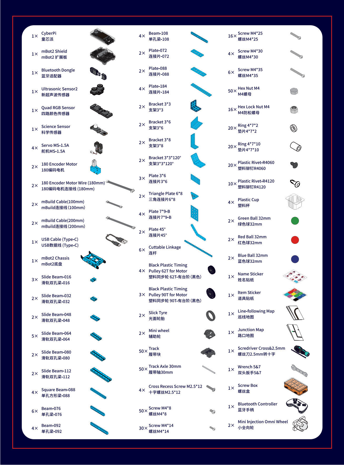 :::warning
Note: Keep the parts properly after each use so that you can reuse them in other projects.
:::warning
Note: Keep the parts properly after each use so that you can reuse them in other projects.
:::
3. Learn about the main components
- This kit contains a variety of electronic and structural parts that you can get to know as you go through the course.
- You can also familiarize yourself with these parts before you start the course to quickly get into the swing of things.
- The kit includes a CyberPi main control board and an mBot2 shield. They work together to power and control other electronic parts, including encoder motors, servos, and sensors. | Name | Quantity | Documentation | | --- | --- | --- | | CyberPi | 1 | For technical information on CyberPi, see makeblock.com/en/docs/cyberpi/cyberpi
For the operation guide of CyberPi, see makeblock.com/en/docs/cyberpi/cyberpi-start | | mBot2 Shield | 1 | For technical information on mBot2 Shield, see makeblock.com/en/docs/cyberpi/mbot2-shield | | Bluetooth Dongle | 1 | For the operation guide of Bluetooth Dongle, see makeblock.com/en/docs/cyberpi/wireless-adapter | | Ultrasonic Sensor2 | 1 | For technical information on Ultrasonic Sensor2, see makeblock.com/en/docs/cyberpi/ultrasonic_sensor_2 | | Quad RGB Sensor | 1 | For technical information on Quad RGB Sensor, see makeblock.com/en/docs/cyberpi/quad_rgb_sensor | | Science Sensor | 1 | For technical information on Science Sensor, see makeblock.com/en/docs/cyberpi/science_sensor | | Servo MS-1.5A | 4 | For technical information on Servo MS-1.5A, see makeblock.com/en/docs/cyberpi/ms-1.5a_servo | | 180 Encoder Motor | 2 | For technical information on 180 Encoder Motor, see makeblock.com/en/docs/cyberpi/180-optical-encoder-motor | | Bluetooth Controller | 1 | For technical information on Bluetooth Controller, see makeblock.com/en/docs/cyberpi/bluetooth_controller |
4. Courses
Documents are on the way. Stay tuned!
5. Explore beyond
You can use the parts to build your own robot and program it using mBlock5 to bring your ideas to life.
Programming guide
To program the parts in mBlock5, you need to add the corresponding extensions first.
For example, if you uses a CyberPi, an mBot2 shield, encoder motors, and an ultrasonic sensor to build the robot, after adding **CyberPi **to the device library and connecting it, you also need to add the mBot2 shield extension (which contains the blocks for encoder motors) and the ultrasonic sensor extension.

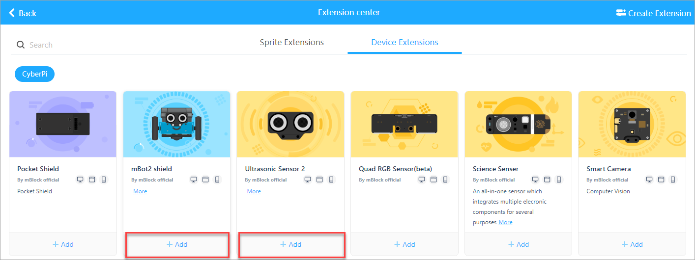 Alternatively, you can add mBot2 to the device library to load the required extensions in one go.
 :::tips
Note: This mBot2 one-time loading feature is currently only supported in the web version of mBlock5.
:::
:::tips
Note: This mBot2 one-time loading feature is currently only supported in the web version of mBlock5.
:::
After adding the extensions successfully, you can drag the blocks to the Blocks area and start programming.

Get more hardware
There is a wide range of peripherals that can be added to the kit to bring your ideas to life. Contact us (https://education.makeblock.com/contact-us/) if you want to take them home.
You can also find more technical information from our CyberPi Series User Manual makeblock.com/en/docs/cyberpi
6. About the competition
MakeX is an international robotics competition and education platform that promotes multidisciplinary learning within the fields of science and technology. It aims at building a world where STEAM education is highly appreciated and where young people are passionate about innovation by engaging them in exciting Robotics Competition, STEAM Carnival, Tech Event, Educational Conference etc.
MakeX Starter is a multi-tasking competition program for elementary school students aged 6-13.
The competition integrates the automatic stage and the manual stage, which greatly enhances fun and participation experience of the competition. The concept of multiple missions and the alliance cooperation design fully exercises the abilities of critical thinking and strategic planning of contestants, as well as improve the ability of communication and cooperation between alliance teams.
 To view information about registration, entry requirements, and available competitions, visit www.makex.cc/en
Or contact us by email: makex_overseas@makeblock.com (overseas) makex@makeblock.com (China)
7. Online support
If you encounter any product quality issues or find any parts missing when you open the package, contact us for after-sales services at support@makeblock.com
We would also appreciate it if you could give us your feedback on the product at cyber.list@makeblock.com
8. More information
CyberPi Series User Manual makeblock.com/en/docs/cyberpi CyberPi Operation Guide makeblock.com/en/docs/cyberpi/cyberpi-start mBot2 Operation Guide makeblock.com/en/docs/cyberpi/mbot2-start Python API Documentation for CyberPi makeblock.com/en/docs/mcode/cyberpi-api mBlock 5 Online Help makeblock.com/en/docs/mblock-5 mBlock-Python Editor Online Help makeblock.com/en/docs/mcode 2022 MakeX Educational Competition Kits makeblock.com/en/docs/cyberpi/22makex
Getting Started with the 2022 MakeX Starter Add-on Pack
1. Foreword
Thank you for choosing the 2022 MakeX Starter Educational Competition Kit. The kit also comes with courses for the 2022 MakeX Starter Zero Carbon Initiative or for classroom use.
If you are using this kit for the first time, we recommend that you read these instructions carefully to get the most out of it.
2. Unpacking and check
Make sure the following parts are included in the kit. If there is any missing part, contact our after-sales service or distributors.
:::warning
Note: Keep the parts properly after each use so that you can reuse them in other projects.
:::
3. Learn about the main components
- This kit contains a variety of electronic and structural parts that you can get to know as you go through the course.
- You can also familiarize yourself with these parts before you start the course to quickly get into the swing of things.
- The kit includes a CyberPi main control board and an mBot2 shield. They work together to power and control other electronic parts, including encoder motors, servos and sensors. | Name | Quantity | Documentation | | --- | --- | --- | | Bluetooth Dongle | 1 | For the operation guide of Bluetooth Dongle, see makeblock.com/en/docs/cyberpi/wireless-adapter | | Science Sensor | 1 | For technical information on Science Sensor, see makeblock.com/en/docs/cyberpi/science_sensor | | Servo MS-1.5A | 4 | For technical information on Servo MS-1.5A, see makeblock.com/en/docs/cyberpi/ms-1.5a_servo | | Bluetooth Controller | 1 | For technical information on Bluetooth Controller, see makeblock.com/en/docs/cyberpi/bluetooth_controller |
4. Courses
Documents are on the way. Stay tuned!
5. Explore beyond
You can use the parts to build your own robot and program it using mBlock5 to bring your ideas to life.
Programming guide
To program the parts in mBlock5, you need to add the corresponding extensions first.
For example, if you uses a CyberPi, an mBot2 shield, encoder motors, and an ultrasonic sensor to build the robot, after adding **CyberPi **to the device library and connecting it, you also need to add the mBot2 shield extension (which contains the blocks for encoder motors) and the ultrasonic sensor extension.
Alternatively, you can add mBot2 to the device library to load the required extensions in one go.
:::tips
Note: This mBot2 one-time loading feature is currently only supported in the web version of mBlock5.
:::
After adding the extensions successfully, you can drag the blocks to the Blocks area and start programming.
Get more hardware
There is a wide range of peripherals that can be added to the kit to bring your ideas to life. Contact us (https://education.makeblock.com/contact-us/) if you want to take them home.
You can also find more technical information from our CyberPi Series User Manual makeblock.com/en/docs/cyberpi
6. About the competition
MakeX is an international robotics competition and education platform that promotes multidisciplinary learning within the fields of science and technology. It aims at building a world where STEAM education is highly appreciated and where young people are passionate about innovation by engaging them in exciting Robotics Competition, STEAM Carnival, Tech Event, Educational Conference etc.
MakeX Starter is a multi-tasking competition program for elementary school students aged 6-13.
The competition integrates the automatic stage and the manual stage, which greatly enhances fun and participation experience of the competition. The concept of multiple missions and the alliance cooperation design fully exercises the abilities of critical thinking and strategic planning of contestants, as well as improve the ability of communication and cooperation between alliance teams.
To view information about registration, entry requirements, and available competitions, visit www.makex.cc/en
Or contact us by email: makex_overseas@makeblock.com (overseas) makex@makeblock.com (China)
7. Online support
If you encounter any product quality issues or find any parts missing when you open the package, contact us for after-sales services at support@makeblock.com
We would also appreciate it if you could give us your feedback on the product at cyber.list@makeblock.com
8. More information
CyberPi Series User Manual makeblock.com/en/docs/cyberpi CyberPi Operation Guide makeblock.com/en/docs/cyberpi/cyberpi-start mBot2 Operation Guide makeblock.com/en/docs/cyberpi/mbot2-start Python API Documentation for CyberPi makeblock.com/en/docs/mcode/cyberpi-api mBlock 5 Online Help makeblock.com/en/docs/mblock-5 mBlock-Python Editor Online Help makeblock.com/en/docs/mcode 2022 MakeX Educational Competition Kits makeblock.com/en/docs/cyberpi/22makex
Introduction to the 2022 MakeX Starter Arena
This kit does not include the MakeboX and frame.
1. Basic information
2022 MakeX Starter Arena
| Name | 2022 MakeX Starter Arena |
|---|---|
| SKU | P1090044 |
| EAN | 6928819513624 |
| Package type | Paper box |
| Package size | 522162329 mm |
| 3mm (thickness)*80mm (inner diameter)*1190mm (length) (Map) | |
| Gross weight (including packaging) | 5.68kg (88.2oz) |
| Others | Remote control and battery not included |
2. Overview
If you want to save money by making your own frames, only want to use the arena for practice, or have already purchased a MakeX starter frame for the 2020 or 2021 season, then we recommend you purchase the **2022 MakeX Starter Arena **for practice or arena upgrades.
3. Parts list
| Name | 2022 MakeX Starter Arena |
|---|---|
| Zero Carbon Map | 2 |
| Red Cube 70mm | 3 |
| Blue Cube 70mm | 2 |
| Yellow Cube 70mm | 6 |
| Yellow Cube 120mm | 2 |
| Red Ball 32mm | 2 |
| Blue Ball 32mm | 20 |
| Green Ball 32mm | 60 |
| PU Ball | 1 |
| Wrench 5&7 | 1 |
| Scredriver Cross&2.5mm | 1 |
| Plastic Cup | 1 |
| Bracket 3*8 | 60 |
| Hinge 40*24mm | 4 |
| Plate-184 | 20 |
| Slide Beam-064 | 2 |
| Plate 3*6 | 60 |
| Bracket 3*3 | 2 |
| Plastic Rivet-R4060 | 6 |
| Hex Lock Nut M4 | 1 |
| Round Ball Rack | 2 |
| Beam-140 | 12 |
| Board A | 5 |
| Board B | 5 |
| Stickers | 2 |
| Bracket 3*6 | 2 |
| Triangle board | 5 |
| Screw M4*8 | 1 |
| Screw M4*14 | 1 |
| Hex Nut M4 | 1 |
| Strip iron | 40 |
| Magnetic column | 35 |
| Magnet sheet | 40 |
| Plate-184 | 20 |
4. Assembly instruction
After checking the number of parts, refer to the following document to assemble the 2022 MakeX Starter Arena. 2022 MakeX Starer零碳行动场地搭建步骤图_说明书_V1.0_D1.1.2_KD010419000_view.pdf 2022 MakeX Starer零碳行动场地搭建步骤图_说明书_V1.0_D1.1.2_KD010419000_view.pdf
5. More information
Getting started with the 2022 MakeX Starter Educational Competition Kit:makeblock.com/en/docs/cyberpi/22starter-start Introduction to the 2022 MakeX Starter Add-on Pack:makeblock.com/en/docs/cyberpi/starter-add-on mBlock online help:makeblock.com/en/docs/cyberpi/mbot2-mobile-coding mBot2 operation guide: makeblock.com/en/docs/cyberpi/mbot2-start Introduction to the 2022 MakeX competitions and kits:makeblock.com/en/docs/cyberpi/22makex
Introduction to the 2022 MakeX Starter Arena and Frame
This kit does not include the MakeboX.
1. Basic information
2022 MakeX Starter Arena and Frame
| Name | 2022 MakeX Starter Arena and Frame |
|---|---|
| SKU | P1090045 |
| EAN | 6928819513617 |
| Package type | Paper box |
| Package size | 445357250mm |
| 1220135120mm | |
| Map packaging: 3mm(thickness)*80mm(inner diameter)*1190mm(length) | |
| Gross weight (including packaging) | 15.48kg (546.04oz) |
| Others | Remote control and battery not included |
2. Overview
If this is your first MakeX Starter competition, or if you would like to purchase a complete package for practice or hosting a MakeX competition, purchase the** 2022 MakeX Starter Arena and Frame**. This set includes the MakeX Starter Frame Expansion Kit V2.0 and the 2022 MakeX Starter Arena.
3. Parts list
Make sure the following parts are included in the kit. If there is any missing part, contact our after-sales service or distributors.
| Name | **2022 MakeX Starter and Frame ** |
|---|---|
| Zero Carbon Map | 1 |
| Red Cube 70mm | 1 |
| Blue Cube 70mm | 1 |
| Yellow Cube 70mm | 6 |
| Yellow Cube 120mm | 2 |
| Red Ball 32mm | 17 |
| Blue Ball 32mm | 17 |
| Green Ball 32mm | 6 |
| PU Ball | 2 |
| Wrench 5&7 | 1 |
| Allen Key 1.5mm | 1 |
| Scredriver Cross&2.5mm | 1 |
| Plastic Cup | 2 |
| Bracket 3*8 | 4 |
| Hinge 40*24mm | 2 |
| Plate-184 | 5 |
| Slide Beam-064 | 12 |
| Plate 3*6 | 5 |
| Bracket 3*3 | 2 |
| Plastic Rivet-R4060 | 60 |
| Hex Lock Nut M4 | 20 |
| Round Ball Rack | 2 |
| Beam-140 | 2 |
| Board A | 4 |
| Board B | 4 |
| Stickers | 1 |
| Bracket 3*6 | 2 |
| Triangle board | 1 |
| Screw M4*8 | 60 |
| Screw M4*14 | 20 |
| Hex Nut M4 | 60 |
| Strip iron | 35 |
| Magnetic column | 40 |
| Magnet sheet | 40 |
| Flat Beam 1550-1126 | 12 |
| Octagonal Pillar-45 | 12 |
| Octagonal Pillar Cover | 24 |
| Flat Beam Lock | 24 |
| Handled Hex Allen Key | 1 |
| Plate-184 | 5 |
| Rectangular Nut M4 | 2 |
| MakeboX Bracket | 1 |
4. Assembly instruction
After checking the number of parts, refer to the following document to assemble the 2022 MakeX Starter Arena. 2022 MakeX Starer零碳行动场地搭建步骤图_说明书_V1.0_D1.1.2_KD010419000_view.pdf
5. More information
Getting started with the 2022 MakeX Starter Educational Competition Kit:makeblock.com/en/docs/cyberpi/22starter-start mBlock online help:makeblock.com/en/docs/cyberpi/mbot2-mobile-coding mBot2 operation guide: makeblock.com/en/docs/cyberpi/mbot2-start Introduction to the 2022 MakeX competitions and kits:makeblock.com/en/docs/cyberpi/22makex
Introduction to the MakeX Starter Frame Expansion Kit V2.0
1. Basic information
MakeX Starter Frame Expansion Kit V2.0
| Name | MakeX Starter Frame Expansion Kit V2.0 |
|---|---|
| SKU | P1090046 |
| EAN | 6928819513631 |
| Package type | Paper box |
| Package size | 290223100 mm |
| 1220135120 mm | |
| Gross weight (including packaging) | 10.1kg (356.3oz) |
| Others | Remote control and battery not included |
2. Overview
For the 2022 MakeX Starter competition, we have 2 different sets of arena and a newly upgraded frame expansion kit for users with different needs.
If you have purchased the** 2022 MakeX Starter Arena **and want to have a better contest experience with a frame, or if you are hosting MakeX competitions, which require standard frames, then you can purchase MakeX Starter Frame Expansion Kit V2.0 as an add-on.
Version statement
- To reduce the time spent in arena assembly, and to avoid discrepancy in referee review due to incorrect arena orientation, we standadize the length of the flat beams for the 2022 season.
- The MakeX Starter Frame Expansion Kit V2.0 uses only 1126mm flat beams, replacing the 1173mm flat beams of Kit V1.0. This makes Kit V2.0 shorter in width by 54mm compared to** Kit V1.0**.
Difference in usage scenarios
The differences in the usage scenarios between Kit V1.0 and Kit V2.0 are as follows:
| Practice | Hosting competitions | MakeX competitions | |
|---|---|---|---|
| Kit V1.0 | Supports | Supports | Not support |
| Kit V2.0 | Supports | Supports | Supports |
"Double frame" mode
Ideally, you should build a complete 2022 MakeX Starter arena on a field of approximately 2.44*2.44m as shown in assembly instruction.
But in many cases, you may not have a large enough field. Therefore, we give you 2 extra flat beams in the Kit V2.0, so you can build 2 complete "0" shaped frames. Although this will be different from the final "8" shaped arena, it will help you teach and practice for the MakeX Starter competition in a more flexible field.
3. Parts list
Make sure the following parts are included in the kit. If there is any missing part, contact our after-sales service or distributors.
| Name | MakeX Starter Frame Expansion Kit V2.0 |
|---|---|
| Wrench 5&7 | 1 |
| Scredriver Cross&2.5mm | 1 |
| Plate 3*6 | 1 |
| Screw M4*14 | 10 |
| Hex Nut M4 | 8 |
| Octagonal Pillar-45 | 12 |
| Octagonal Pillar Cover | 24 |
| Flat Beam Lock | 24 |
| Handled Hex Allen Key | 1 |
| Plate-184 | 1 |
| Rectangular Nut M4 | 5 |
| Flat Beam 550-1126 | 12 |
| MakeboX Bracket | 1 |
4. Assembly instruction
After checking the number of parts, refer to the following document to assemble the 2022 MakeX Starter Arena. 2022 MakeX Starer零碳行动场地搭建步骤图_说明书_V1.0_D1.1.2_KD010419000_view.pdf
5. More information
Getting started with the 2022 MakeX Starter Educational Competition Kit:makeblock.com/en/docs/cyberpi/22starter-start mBlock online help:makeblock.com/en/docs/cyberpi/mbot2-mobile-coding mBot2 operation guide: makeblock.com/en/docs/cyberpi/mbot2-start mBot2 operation guide: makeblock.com/en/docs/cyberpi/mbot2-start Introduction to the 2022 MakeX competitions and kits:makeblock.com/en/docs/cyberpi/22makex
Getting Started with the 2022 MakeX Explorer Educational Competition Kit
Thank you for choosing the 2022 MakeX Explorer Educational Competition Kit. If you are using this kit for the first time, we recommend that you read these instructions carefully to get the most out of it.
1. Unpacking and check
Make sure the following parts are included in the kit. If there is any missing part, contact our after-sales service or distributors.
:::warning
Note: Keep the parts properly after each use so that you can reuse them in other projects.
:::
2. Learn about the main components
- This kit contains a variety of electronic and structural parts that you can get to know as you go through the course.
- You can also familiarize yourself with these parts before you start the course to quickly get into the swing of things.
- The kit includes a CyberPi main control board and an mBot2 shield. They work together to power and control other electronic parts, including encoder motors, servos and sensors. | Name | Quantity | Documentation | | --- | --- | --- | | CyberPi | 1 | For technical information on CyberPi, see makeblock.com/en/docs/cyberpi/cyberpi For the operation guide of CyberPi, see makeblock.com/en/docs/cyberpi/cyberpi-start | | mBot2 Shield | 1 | For technical information on mBot2 Shield, see makeblock.com/en/docs/cyberpi/mbot2-shield | | Bluetooth Controller | 1 | For technical information on Bluetooth Controller, see makeblock.com/en/docs/cyberpi/bluetooth_controller | | Bluetooth Dongle | 1 | For the operation guide of Bluetooth Dongle, see makeblock.com/en/docs/cyberpi/wireless-adapter | | Ultrasonic Sensor | 1 | For technical information on Ultrasonic Sensor, see makeblock.com/en/docs/cyberpi/ultrasonic_sensor_2 | | Quad RGB Color Sensor | 1 | For technical information on Quad RGB Color Sensor, see makeblock.com/en/docs/cyberpi/quad_rgb_sensor | | MS-1.5A Servo | 3 | For technical information on MS-1.5A Servo, see http://docs.makeblock.com/diy-platform/en/electronic-modules/motors/meds15-servo-motor.html | | 130 High-speed DC Motor | 2 | For technical information on 130 High-speed DC Motor, see makeblock.com/en/docs/cyberpi/dh68v8 | | MECDS-150 Servo | 1 | For technical information on MECDS-150 Servo, see http://docs.makeblock.com/diy-platform/en/electronic-modules/motors/meds15-servo-motor.html | | LiPo Rechargeable Battery | 1 | For technical information on mBot2 Li-ion Rechargeable Battery Enhancement Pack, see makeblock.com/en/docs/cyberpi/mbot2-battery-enhancement | | Battery Charger Adapter Board | 1 | | | Power Adapter | 1 | | | Encoder Motor | 2 | For technical information on Encoding Motor Cable(180mm), see makeblock.com/en/docs/cyberpi/180-optical-encoder-motor | | Encoding Motor Cable(180mm) | 2 | |
3. Courses
Documents are on the way. Stay tuned!
4. Explore beyond
You can use the parts to build your own robot and program it using mBlock5 to bring your ideas to life.
Programming guide
To program the parts in mBlock5, you need to add the corresponding extensions first.
For example, if you use a CyberPi, a mBot2 shield, encoder motors, and an ultrasonic sensor to build the robot, after adding **CyberPi **to the device library and connecting it, you also need to add the mBot2 shield extension (which contains the blocks for encoder motors) and the ultrasonic sensor extension.
Alternatively, you can add mBot2 to the device library to load the required extensions at once.
:::tips
Note: This mBot2 one-time loading feature is currently only supported in the web version of mBlock5.
:::
After adding the extensions successfully, you can drag the blocks to the Blocks area and start programming.
Get more hardware
There is a variety of peripherals that can be added to the kit to bring your ideas to life. Contact us (https://education.makeblock.com/contact-us) if you want to take them home.
You can also find more technical information from our CyberPi series User Manual makeblock.com/en/docs/cyberpi
5. About the competition
MakeX is an international robotics competition and education platform that promotes multidisciplinary learning within the fields of science and technology. It aims at building a world where STEAM education is highly appreciated and where young people are passionate about innovation by engaging them in exciting Robotics Competition, STEAM Carnival, Tech Event, Educational Conference, etc.
MakeX Explorer is a confrontational competition program for elementary and junior high school students aged 8-15.
This program fully integrates the essence of sports events and is highly interesting and a delight to watch. The competition requires the contestants to design and build robots from scratch, which systematically develops the contestants' comprehensive abilities in robot design, mechanical construction, and programming. Also, the form of alliance confrontation improves the contestants' ability to solve imperative problems and strategic thinking.
To view information about registration, entry requirements, and available competitions, visit www.makex.cc
Or contact us by email: makex_overseas@makeblock.com (overseas) makex@makeblock.com (China)
6. Online support
If you encounter any product quality issues or find any parts missing when you open the package, contact us for after-sales services at support@makeblock.com
We would also appreciate it if you could give us your feedback on the product at cyber.list@makeblock.com
7. More information
Introduction to the 2022 MakeX Explorer Educational Competition Kit:makeblock.com/en/docs/cyberpi/22explorer CyberPi Series User Manual makeblock.com/en/docs/cyberpi CyberPi Operation Guide makeblock.com/en/docs/cyberpi/cyberpi-start mBot2 Operation Guide makeblock.com/en/docs/cyberpi/mbot2-start Python API Documentation for CyberPi makeblock.com/en/docs/mcode/cyberpi-api mBlock 5 Online Help makeblock.com/en/docs/mblock-5 mBlock-Python Editor Online Help makeblock.com/en/docs/mcode 2022 MakeX Educational Competition Kits makeblock.com/en/docs/cyberpi/22makex
Introduction to the 2022 MakeX Explorer Arena
The kit does not include the MakeboX.
1. Basic information
2022 MakeX Explorer Arena
| Name | 2022 MakeX Explorer Arena |
|---|---|
| SKU | P1090040 |
| EAN | 6928819513662 |
| Package type | Paper box |
| Package size | 365355310mm |
| 1175210115mm | |
| 2386.9 * 2426.9 mm(map) | |
| 1175210115mm | |
| Gross weight (including packaging) | 30.775kg (1085.556oz) |
| Others | Remote control and battery not included |
2. Overview
This kit contains a map, a frame, props and other parts needed for the 2022 MakeX Explorer competition, which can be used for offline training and competition hosting.
3. Parts list
Make sure the following parts are included in the kit. If there is any missing part, contact our after-sales service or distributors.
| Name | Quantity |
|---|---|
| Flat Beam 1126 | 16 |
| MakeX Board Blue&Black | 4 |
| MakeX Board Red&Black | 4 |
| Flat Beam 1126 | 4 |
| Octagonal Pillar-600 | 2 |
| Octagonal Pillar-250 | 8 |
| Octagonal Pillar-125 | 2 |
| Middle Board A | 1 |
| Middle Board B | 2 |
| Flat Beam Lock | 40 |
| Extension Connector | 4 |
| 90° Connector | 16 |
| Octagonal Pillar Cover | 24 |
| Rectangular Nut M4 | 30 |
| Plate | 3 |
| Yellow Ball 70mm | 16 |
| Green Ball 100mm | 6 |
| Yellow Cube 70mm | 5 |
| Lean Beam-248 | 4 |
| Lean Beam-424 | 4 |
| Lean Beam-504 | 4 |
| MakeboX Bracket | 1 |
| Height Setting Bar | 8 |
| Flag Bucket | 2 |
| 1 | |
| Max in Red | 1 |
| Screw M3*8 | 2 |
| Flag Bucket | 2 |
| 1 | |
| Max in Blue | 2 |
| Screw M3*8 | 2 |
| Screw M4*40 | 20 |
| Screw M4*14 | 4 |
| Screw M4*8 | 6 |
| Hex Nut M4 | 20 |
| Screw M6*12 | 16 |
| Screw M6*16 | 2 |
| Hex Nut M6 | 18 |
| Spacer 4.2730 | 20 |
| Hook-and-Loop Fastener 20mm (Hook) | 1 |
| Hook-and-Loop Fastener 21mm (Loop) | 2 |
| Goal Net | 2 |
| EVA Tape 20*8mm | 2 |
| Cable Tie | 100 |
| Transparent Tape | 1 |
| 3M Double-sided Nano Tape | 1 |
| Hex Allen Key T30 | 1 |
| Allen Key 5mm | 1 |
| Screwdriver Cross&2.5mm | 1 |
4. Assembly instruction
After checking the number of parts, refer to the following document to assemble the 2022 MakeX Starter Arena. 2022 MakeX Explorer 碳锁先锋_场地搭建步骤_说明书_V1.0_D1.1.2_ KD010421000_preview.pdf
5. More information
Getting started with the 2022 MakeX Explorer Educational Competition Kit:makeblock.com/en/docs/cyberpi/22explorer-start mBlock online help:makeblock.com/en/docs/cyberpi/mbot2-mobile-coding mBot2 operation guide: makeblock.com/en/docs/cyberpi/mbot2-start Introduction to the 2022 MakeX competitions and kits:makeblock.com/en/docs/cyberpi/22makex
Getting Started with the 2022 MakeX Challenge Educational Competition Kit
1. Foreword
Thank you for choosing the 2022 MakeX Challenge Educational Competition Kit.
If you are using this kit for the first time, we recommend that you read these instructions carefully to get the most out of it.
2. Unpacking and check
Make sure the following parts are included in the kit. If there is any missing part, contact our after-sales service or distributors.
:::warning
Note: Keep the parts properly after each use so that you can reuse them in other projects.
:::
3. Learn about the main components
- This kit contains a variety of electronic and structural parts that you can get to know as you go through the course.
- You can also familiarize yourself with these parts before you start the course to quickly get into the swing of things. | Name | Picture | Documentation | | --- | --- | --- | |
Mainboard NovaPi | | For technical information and the operation guide on NovaPi, see makeblock.com/en/docs/maker_platform/novapi |
|
Power Expansion Board | | For technical information on Power Expansion Board, see
makeblock.com/en/docs/maker_platform/power_extension_board |
|
Power Management Module | | 电源管理模块的技术信息,参阅
makeblock.com/en/docs/maker_platform/ayttzq |
|
180 Smart Encoder Motor | | For technical information on 180 Smart Encoder Motor, see makeblock.com/en/docs/maker_platform/180-smart-encoder-motor |
|
37mm DC Motor | | For technical information on 37mm DC Motor , see makeblock.com/en/docs/maker_platform/37-dc-motor |
|
Servo MS-12A | | For technical information on Servo MS-12A, see
makeblock.com/en/docs/maker_platform/smart-servo-12a |
|
Brushless Motor | | For technical information on Brushless Motor, see
makeblock.com/en/docs/maker_platform/brushless-motor |
|
Structural parts | | For technical information on structural parts, see makeblock.com/en/docs/maker_platform/mechanical_structure |
|
Bluetooth Dongle | | For the operation guide of Bluetooth Dongle, see makeblock.com/en/docs/cyberpi/wireless-adapter |
|
Bluetooth Controller | | For technical information on Bluetooth Controller, see
makeblock.com/en/docs/cyberpi/bluetooth_controller |
Simple chassis assembly
4. Courses
Documents are on the way. Stay tuned!
5. Explore beyond
You can use the parts to build your own robot and program it using mBlock5 to bring your ideas to life.
Programming guide
To program the parts in mBlock5, you need to add the corresponding extensions first.
For example, if you use a CyberPi, an mBot2 shield, encoder motors, and an ultrasonic sensor to build the robot, after adding **CyberPi **to the device library and connecting it, you also need to add the mBot2 shield extension (which contains the blocks for encoder motors) and the ultrasonic sensor extension.
Alternatively, you can add mBot2 to the device library to load the required extensions in one go.
:::tips
Note: This mBot2 one-time loading feature is currently only supported in the web version of mBlock5.
:::
After adding the extensions successfully, you can drag the blocks to the Blocks area and start programming.
Get more hardware
There is a wide range of peripherals that can be added to the kit to bring your ideas to life. Contact us (https://education.makeblock.com/contact-us/) if you want to take them home.
You can also find more technical information from our CyberPi Series User Manual makeblock.com/en/docs/cyberpi
6. About the competition
MakeX is an international robotics competition and education platform that promotes multidisciplinary learning within the fields of science and technology. It aims at building a world where STEAM education is highly appreciated and where young people are passionate about innovation by engaging them in exciting Robotics Competition, STEAM Carnival, Tech Event, Educational Conference, etc.
MakeX Challenge is a highly confrontational competition program for middle and vocational school students aged 11-18.
This program is very confrontational and enjoyable to watch, and the simple and easy-to-understand rules enhance the overall experience of participation and engagement. The design and construction of bigger robots and programming can better improve the contestants' design abilities and multi-dimensional thinking abilities of advanced robots. Also, the contestants are exercising logical thinking, strategic analysis, communication and cooperation, and improving decision-making abilities in the competition.
To view information about registration, entry requirements and available competitions, visit www.makex.cc/en
Or contact us by email: makex_overseas@makeblock.com (overseas) makex@makeblock.com (China)
7. Online support
If you encounter any product quality issues or find any parts missing when you open the package, contact us for after-sales services at support@makeblock.com
We would also appreciate it if you could give us your feedback on the product at cyber.list@makeblock.com
8. More information
CyberPi Series User Manual makeblock.com/en/docs/cyberpi CyberPi Operation Guide makeblock.com/en/docs/cyberpi/cyberpi-start Introduction to the 2022 MakeX Challenge Educational Competition Kit makeblock.com/en/docs/cyberpi/22challenge mBot2 Operation Guide makeblock.com/en/docs/cyberpi/mbot2-start Python API Documentation for CyberPi makeblock.com/en/docs/mcode/cyberpi-api mBlock 5 Online Help makeblock.com/en/docs/mblock-5 mBlock-Python Editor Online Help makeblock.com/en/docs/mcode 2022 MakeX Educational Competition Kits makeblock.com/en/docs/cyberpi/22makex
Getting Started with the 2022 MakeX Challenge Upgrade Pack for Intelligent Innovator
1. Foreword
Thank you for choosing the 2022 MakeX Challenge the 2022 MakeX Challenge Upgrade Pack for Intelligent Innovator.
If you are using this kit for the first time, we recommend that you read these instructions carefully to get the most out of it.
2. Unpacking and check
Make sure the following parts are included in the kit. If there is any missing part, contact our after-sales service or distributors.
:::warning
Note: Keep the parts properly after each use so that you can reuse them in other projects.
:::
3. Learn about the main components
- This kit contains a variety of electronic and structural parts that you can get to know as you go through the course.
- You can also familiarize yourself with these parts before you start the course to quickly get into the swing of things.
| Name | Picture | Documentation |
| --- | --- | --- |
| 180 Smart Encoder Motor | | For technical information on 180 Smart Encoder Motor, see
makeblock.com/en/docs/maker_platform/180-smart-encoder-motor |
| Servo MS-12A | | For technical information on Servo MS-12A, see
makeblock.com/en/docs/maker_platform/smart-servo-12a |
| Mechanical / structural parts | | For technical information on Mechanical / structural parts, see makeblock.com/en/docs/maker_platform/mechanical_structure |
4. Courses
Documents are on the way. Stay tuned!
5. Explore beyond
You can use the parts to build your own robot and program it using mBlock5 to bring your ideas to life.
Get more hardware
There is a wide range of peripherals that can be added to the kit to bring your ideas to life. Contact us (https://education.makeblock.com/contact-us/) if you want to take them home.
You can also find more technical information from our CyberPi Series User Manual makeblock.com/en/docs/cyberpi
6. About the competition
MakeX is an international robotics competition and education platform that promotes multidisciplinary learning within the fields of science and technology. It aims at building a world where STEAM education is highly appreciated and where young people are passionate about innovation by engaging them in exciting Robotics Competition, STEAM Carnival, Tech Event, Educational Conference, etc.
MakeX Challenge is a highly confrontational competition program for middle and vocational school students aged 11-18.
This program is very confrontational and enjoyable to watch, and the simple and easy-to-understand rules enhance the overall experience of participation and engagement. The design and construction of bigger robots and programming can better improve the contestants' design abilities and multi-dimensional thinking abilities of advanced robots. Also, the contestants are exercising logical thinking, strategic analysis, communication and cooperation, and improving decision-making abilities in the competition.
To view information about registration, entry requirements, and available competitions, visit www.makex.cc/en
Or contact us by email: makex_overseas@makeblock.com (overseas) makex@makeblock.com (China)
7. Online support
If you encounter any product quality issues or find any parts missing when you open the package, contact us for after-sales services at support@makeblock.com
We would also appreciate it if you could give us your feedback on the product at cyber.list@makeblock.com
8. More information
CyberPi Series User Manual makeblock.com/en/docs/cyberpi CyberPi Operation Guide makeblock.com/en/docs/cyberpi/cyberpi-start Introduction to the 2022 MakeX Challenge Upgrade Pack for Intelligent Innovator makeblock.com/en/docs/cyberpi/challenge-upgrade mBot2 Operation Guide makeblock.com/en/docs/cyberpi/mbot2-start Python API Documentation for CyberPi makeblock.com/en/docs/mcode/cyberpi-api mBlock 5 Online Help makeblock.com/en/docs/mblock-5 mBlock-Python Editor Online Help makeblock.com/en/docs/mcode Introduction to the 2022 MakeX Educational Competition Kits makeblock.com/en/docs/cyberpi/22makex
Introduction to the 2022 MakeX Challenge Arena
Includes only some of the parts and needs to be used with the 2020-2021 MakeX Challenge Arena for Intelligent Innovator.
1. Basic information
2022 MakeX Challenge Arena
| Name | 2022 MakeX Challenge Arena |
|---|---|
| SKU | P1090036 |
| EAN | 6928819513570 |
| Package type | Paper box |
| Package size | 663388255 mm |
| 290223100 mm | |
| 1000284112 mm*2 | |
| 1056384293 mm | |
| 522162329 mm | |
| 2.0980525 mm(Metal net) | |
| 390390185(Hanging Basket) | |
| 3mm(thickness)*92mm(inner diameter)*1590mm(length)(Map) | |
| Gross weight (including packaging) | 83.05KG (2929.5oz) |
| Others | Remote control and battery not included |
2. Overview
This kit contains the maps, frames, props, and other parts needed for the 2022 MakeX Challenge competition, which can be used for offline training and competition hosting.
3. Parts list
| Name | Quantity |
|---|---|
| Metal Net | 6 |
| Hanging Basket | 2 |
| Bottle Red&Black | 12 |
| Bottle Blue&Black | 12 |
| Flat Beam Lock | 126 |
| Flat Beam Lock 45°-Left | 12 |
| Flat Beam Lock 45°-Right | 12 |
| Octagonal Pillar-960 | 12 |
| Flat Beam 960 | 6 |
| Flat Beam 960 | 36 |
| Bottle Support | 12 |
| Cube Partition Board | 3 |
| Cube Cover Board | 3 |
| Black Protection Board | 2 |
| Makex Board Blue&Black | 7 |
| Makex Board Red&Black | 7 |
| Yellow Cube 120mm | 9 |
| Cube Sticker A | 5 |
| Cube Sticker B | 5 |
| Yellow Ball 70mm | 64 |
| Octagonal Pillar-400 | 4 |
| Octagonal Pillar-250 | 4 |
| Flat Beam 220 | 10 |
| Flat Beam 160 | 22 |
| Flat Beam 45° | 12 |
| Octagonal Pillar Cover | 28 |
| Flat Beam Cover | 22 |
| Allen Key | 3 |
| Rectangular Nut M4 | 32 |
| Screw M4*10 | 12 |
| Double-sided Fabric Tape | 1 |
| 3M Double-sided Nano Tape | 1 |
| Octagonal Pillar-45 | 4 |
| Hook-and-Loop Fastener 1150*25mm (Loop) | 4 |
| Combination Screw M4*8 | 20 |
| Screwdriver Cross&2.5mm | 1 |
| Energy Innovator Map | 1 |
4. Assembly instruction
After checking the number of parts, refer to the following document to assemble the 2022 MakeX Challenge Arena. 2022 MakeX Challenge 碳锁先锋_场地搭建步骤_说明书_V1.0_D1.1.1_KD010420000_preview.pdf
5. More information
Getting started with the 2022 MakeX Challenge Educational Competition Kit:makeblock.com/en/docs/cyberpi/22challenge-start mBlock online help:makeblock.com/en/docs/cyberpi/mbot2-mobile-coding mBot2 operation guide: makeblock.com/en/docs/cyberpi/mbot2-start Introduction to the 2022 MakeX competitions and kits:makeblock.com/en/docs/cyberpi/22makex
Introduction to the 2022 MakeX Challenge Upgrade Arena for Intelligent Innovator
1. Basic information
| Name | 2022 MakeX Challenge Upgrade Arena for Intelligent Innovator |
|---|---|
| SKU | P1090037 |
| EAN | 6928819513587 |
| Package type | Paper box |
| Package size | 473345390 mm |
| 1050370185 mm | |
| 3mm(thickness)*92mm(inner diameter)*1590(length)Map | |
| Gross weight (including packaging) | 23.3kg |
| Others | Remote control and battery not included |
2. Overview
If you already have the 2020-2021 MakeX Challenge Arena Kit for Intelligent Innovator (a full arena, not a half arena for practice), you can buy this arena upgrade pack to assemble a full 2022 MakeX Challenge arena.
3. Parts list
Make sure the following parts are included in the kit. If there is any missing part, contact our after-sales service or distributors.
| Name | Quantity |
|---|---|
| Hanging Basket | 2 |
| Bottle Red&Black | 6 |
| Bottle Blue&Black | 6 |
| Flat Beam Lock 45°-Left | 4 |
| Flat Beam Lock 45°-Right | 4 |
| Bottle Support | 12 |
| Cube Partition Board | 3 |
| Cube Cover Board | 3 |
| Black Protection Board | 2 |
| Makex Board Blue&Black | 1 |
| Makex Board Red&Black | 1 |
| Cube Sticker B | 5 |
| Yellow Ball 70mm | 64 |
| Octagonal Pillar-250 | 4 |
| Flat Beam 160 | 8 |
| Flat Beam 45° | 4 |
| Rectangular Nut M4 | 32 |
| Screw M4*10 | 12 |
| Double-sided Fabric Tape | 1 |
| 3M Double-sided Nano Tape | 1 |
| Octagonal Pillar-45 | 4 |
| Hook-and-Loop Fastener 1150*25mm (Loop) | 4 |
| Combination Screw M4*8 | 20 |
| Energy Innovator Map | 1 |
4. Assembly instruction
After checking the number of parts, refer to the following document to assemble the 2022 MakeX Challenge Arena. 2022 MakeX Challenge 碳锁先锋_场地搭建步骤_说明书_V1.0_D1.1.1_KD010420000_preview.pdf
5. More information
Getting started with the 2022 MakeX Challenge Educational Competition Kit:makeblock.com/en/docs/cyberpi/22challenge-start mBlock online help:makeblock.com/en/docs/cyberpi/mbot2-mobile-coding mBot2 operation guide: makeblock.com/en/docs/cyberpi/mbot2-start Introduction to the 2022 MakeX competitions and kits:makeblock.com/en/docs/cyberpi/22makex
CyberPi Operation Guide
Thank you for choosing CyberPi!
If you use CyberPi for the first time, read this guide carefully and follow the instructions so that you won't miss its functions.
1. Before you use CyberPi
1.1 Power on CyberPi
Use a Micro USB cable (Type-C) to connect CyberPi to your PC. The PC can supply power for CyberPi.
:::info Note:
- The Micro USB cable is not included in the package. You need to purchase one separately.
- You can also use a power bank to supply power for CyberPi.
:::
:::info
When charging CyberPi, ensure that the voltage is lower than 6 V. The hardware of CyberPi may be damaged if the voltage is equal to or higher than 6 V.
:::
Alternatively, you can purchase Pocket Shield.
Pocket Shield is equipped with a built-in rechargeable battery that can supply power for CyberPi and provides 2-pin and 3-pin interfaces that can be used to connect servos, LED strips, and motors, which significantly improves the extensibility of CyberPi.
1.2 Know about your CyberPi
1.2.1 Hardware functions
1.2.2 Default functions of the joystick and buttons
CyberPi is equipped with one joystick and two buttons.
On system UIs, the default functions of the joystick and buttons are described as follows.
- Move the joystick up: to select the previous item
- Move the joystick down: to select the next item
- **Move the joystick to the left: **to select the left item
- **Move the joystick to the right: **to select the right item
- **Press the joystick in the middle: **to confirm the selection and enter the lower-level menu, if any
- Button A: to return to the upper-level menu
- **Button B: **to confirm the selection and enter the lower-level menu, if any
2. Enter the CyberOS homepage
CyberPi runs CyberOS.
After being powered on, CyberPi displays the system homepage.
If it doesn't display the homepage, you can press the Home button on the right side of CyberPi to enter the homepage.
After starting CyberOS, you can use the preset programs, set the system language, and update the system through the Internet.
You can exit from the homepage by choosing "Restart Program", and the system automatically executes the last program you've executed.
:::info **Note: **When CyberPi is connected to mBlock 5 and being programmed in Live mode, the HOME button doesn't take effect and you can't enter the homepage by pressing it. :::
2.2 Set the system language
If the default system language is not your native language, you can change it. The following takes the steps for changing the language from English to Chinese as an example:
(1) Enter the homepage, select Settings by moving the joystick up or down, and press B to enter the Settings page.
(2) On the Settings page, select Language by moving the joystick up or down and press button B to enter the Language page.
(3) On the Language page, select 简体中文 by moving the joystick up or down and press button B to complete the setting.
After you set a language, the system switches to the language and returns to the homepage.
2.3 Switch programs
CyberPi can store multiple programs and you can switch them. In addition, CyberPi is delivered with several default example programs on it to help you understand its main functions.
:::info Note:
- Internet access is required for AI and IoT programs, and therefore they are not included in the default example programs and are provided in the example programs on mBlock 5. Find them by choosing Tutorials > Example Programs on mBlock 5.
- The program you upload to CyberPi on mBlock 5 replaces the one you have used last time. The default example programs are provided, and you can restore them by uploading them to your CyberPi. :::
(1) Enter the homepage, select Switch Program by moving the joystick up or down, and press B to enter the Switch Program page.
(2) On the Switch Program page, select a program, for example, Program1, by moving the joystick up or down, and then press button B.
CyberPi restarts and executes Program 1.
CyberPi displays the name of the program first and then prompts you to perform the steps required for executing the program.
3. Start programming
This section describes how to program CyberPi on mBlock 5. You can use the powerful functions of CyberPi through programming.
3.1 Download and install the required software
Currently, CyberPi supports the block-based graphical programming and Python programming. Make sure that you have downloaded and installed the required software.
| Language | Editor | mBlock 5 version | Required software | URL address |
|---|
|
Scratch, MicroPython |
mBlock Block-based Editor | PC client on Windows/Mac
| mBlock 5 for Windows
mBlock 5 for Mac | N/A |
| | | Web version on Windows/Mac
| Google Chrome
mLink2 for Windows
mLink2 for Mac | https://ide.mblock.cc |
| | | Web version on Chromebook
| mLink for Chromebook
For details about how to use mBlock 5 to program CyberPi on Chromebook, see "Programming CyberPi on Chromebook." | https://ide.mblock.cc |
| Scratch | mBlock Block-based Editor | Mobile app
| mBlock 5 app | Use your phone or tablet to scan the QR code:
Alternatively, search for "Makeblock" in app stores. |
| Python, MicroPython | mBlock-Python Editor | Web version on Windows/Mac
| Google Chrome
mLink2 for Windows mLink2 for Mac | https://python.makeblock.com/ |
3.2 Block-based programming
3.2.1 Add and connect CyberPi
(1) Open mBlock 5.
Open mLink2 if you are to use mBlock 5 on the web.
:::info
Note: To use some cloud service functions, you need to sign in to your mBlock 5 account. Sign up an account if you haven't got one.
:::
(2) Use a Micro USB cable (Type-C) to connect CyberPi to your PC.
(3) Click + add on the Devices tab, select CyberPi in the device library, and click OK.
(4) Click Connect to connect CyberPi to mBlock 5.
A message is displayed after CyberPi is connected, indicating that the connection is successful.
(5) Set the programming mode.
mBlock 5 provides two programming modes, namely Live and Upload. You can click to switch the modes.
Live: In this mode, you can view the program execution effect in real time, which facilitates the debugging of the program. In this mode, you must keep CyberPi connected to mBlock 5. If they are disconnected, the program cannot be executed.
Upload: In this mode, you need to upload the compiled program to CyberPi. After being successfully uploaded, the program can still run properly on CyberPi when it is disconnected from mBlock 5.
3.2.2 Example programs
mBlock 5 provides a large number of example programs.
Choose Tutorials > Example Programs and click CyberPi to view example programs provided for CyberPi.
You can select and load a program to view, execute, or upload it to CyberPi.
3.2.3 Block help
mBlock 5 provides multiple types of blocks for CyberPi. If you don't understand a block when using it, you can right-click it and click Help that appears.
3.2.4 Programming languages
mBlock 5 provides two programming languages for CyberPi, namely block-based programming and Python. In Upload mode, you can click the buttons on the right to switch the programming languages.
In addition, when programming CyberPi in the block-based language, you can click the switching button on the right to view the corresponding Python statements (obtained by converting the blocks).
:::tips
Note: You can see Python API Documentation for CyberPi to know about more functions of CyberPi.
:::
3.2.5 Example: Compile the “Marquee” program
Perform the following steps to compile a program using blocks in Live mode to implement the marquee effect of the LEDs on CyberPi.
(1) Set the programming mode to Live.
(2) Set the initial color(s) of the LEDs.
Set the initial colors to red, orange, yellow, green, and cyan.
(3) Set a condition for rolling the colors.
Each time button A on CyberPi is pressed, the colors roll from left to right by one position.
(4) Add an event that triggers the program.
The program is to be executed when you press the space key.
**The Marquee program is complete. **
Press the space key, and then keep pressing button A to see the execution result of the program.
(5) Name the project and save it.
After saving a project, you can click your user image and choose My Projects to view it.
:::info ** Note:** To save projects, you need to sign in to mBlock 5 first. :::
You can also save your project to the local disk.
3.3 Python programming
Open mBlock-Python Editor on Google Chrome. For details about how to program CyberPi on mBlock-Python Editor, see mBlock-Python Editor Online Help.
4. Online help
After-sales services and technical support
If you encounter any product quality problems or find any parts missing or damaged when you open the package, or if you need any technical support, contact us for after-sales services through:** ** support@makeblock.com (Service hours: 9:00–12:00 & 14:00–18:30 from Monday to Friday)
Feedback and suggestions
Should you have any feedback or suggestions on CyberPi, contact our R&D team through: cyber.list@makeblock.com
5. FAQs
How can I design a game with CyberPi?
To ensure user experience, only limited control permission on CyberPi's screen is provided for users currently. More functions are on the way.
Currently, you can use mBlock-Python Editor in combination with some Python libraries such as pygame to implement control over a Python game, using CyberPi as a remote control.
You can find examples in the mBlock-Python Editor Online Help.
Alternatively, you can use the CyberPi Lab extensions to use the latest functions of CyberPi, for which you may need to update the firmware of CyberPi.
6. More information
CyberPi Operation Guide Pocket Shield Operation Guide CyberPi Series User Manual Python API Documentation for CyberPi mBlock 5 Online Help mBlock-Python Editor Online Help
Introduction to mBot2
 Compared to mBot, mBot2 is overall upgraded in its main control board, extensibility, power supply, motion system, sensor design, and chassis.
CyberPi —— main control board
mBot2 uses CyberPi as its main control board. CyberPi is developed independently by Makeblock. For details about CyberPi and how to use it, see CyberPi and CyberPi Operation Guide.
Performance comparison
| **Main control board ** | CyberPi | mCore |
|---|---|---|
| Processor core | ESP32-WROVER-B | ATmega328/P |
| Processor clock frequency | 240 MHz | 20 MHz |
| Onboard ROM | 448 KB | 1 KB |
| Onboard SRAM | 520 KB | 2 KB |
| **SPI Flash ** | 8 MB | / |
| PSRAM | 8 MB | / |
Function comparison
| **Main control board ** | CyberPi | mCore |
|---|---|---|
| Mode switching | No firmware update required | Firmware update required |
| Multi-thread processing | Supported | Not supported |
| Number of programs it can store | 8 | 1 |
| Python | Supported, microPython+Python3 | Not supported |
| Communication mode | Bluetooth + WiFi | |
| WiFi LAN communication | Bluetooth or 2.4G | |
| varying according to product version |
IR communication | | Button input | Joystick (five-direction control) Button × 2 Home button | Button Reset button | | Onboard sensor | Light sensor Microphone (can record sounds and can function as a sound sensor) Gyroscope Accelerometer | Light sensor | | Onboard output | 1.44-inch full-color display Speaker RGB LED × 5 | Buzzer RGB LED × 2 |
mBot2 Shield —— extensibility
The extensibility and power supply of mBot2 depend on mBot2 Shield.
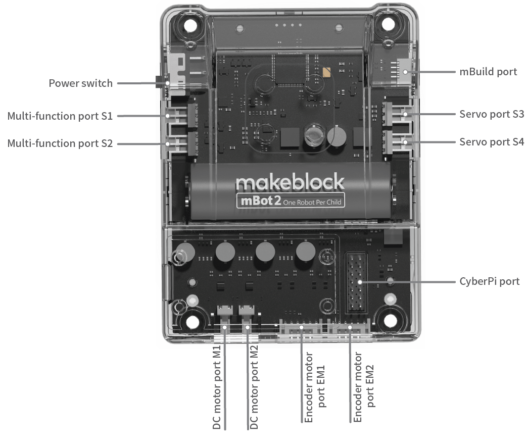
Extensibility comparison
| mBot2 | mBot | |
|---|---|---|
| Encoder motor port | 2 | 0 |
| DC motor port | 2 | 2 |
| Servo port | 4 | 0 |
| Port for LED strips | 2 (also serve as servo ports) | 0 |
| Port for Arduino modules | 2 (also serve as servo ports) | 0 |
| Number of electronic modules it can be extended with | More than 10* | |
| (through the mBuild port) | 4 |
*No more than 10 mBuild modules are recommended for the best performance experience.
Power supply
The power supply for mBot2 has been upgraded.
Power supply comparison
| mBot2 | mBot | |
|---|---|---|
| Capacity | 2500 mAh | 1800 mAh |
| Discharge rate | 3C | 1C |
| Rated power | 27.75 W | 6.66 W |
Charging/Power supplying
The capacity of the battery on mBot2 Shield is 2500 mAh. You need to charge mBot2 Shield through CyberPi. It can be charged while being used.
To charge mBot2 Shield, connect it to CyberPi first, and then use a USB cable (Type-C) to connect CyberPi to a computer or power bank.
The following table describes the charging and power supplying of mBot2 Shield.
| Battery life Supplies power for mBot2 with loads, such as servos and motors, in common application scenarios. | 2.5 hours–5 hours When mBot2 keeps moving or keeps operating with loads: 2.5 hours | | --- | --- | | Upper limit of battery life mBot2 operates in the sleep mode with the screen off. | More than 24 hours | | Time to fully charge the battery | 1 hour–2 hours |
Motion system
mBot2 uses the high-precision encoder motors that have been used in mBot Ranger, and we have redesigned the circuits for the encoder motors to ensure the operation safety and quality.
Motor performance comparison
| mBot2 | mBot | |
|---|---|---|
| Rotational speed range | 1–200 RPM | 47–118RPM±10% |
| **Rotational angle accuracy ** | ≤5° | N/A |
| Detection accuracy | 1° | N/A |
| Torque (in operation) | 1500 g·cm | ≥672 g·cm |
| Material of the output shaft | Metal | Plastic |
Motor control comparison
| mBot2 | mBot | |
|---|---|---|
| Turning | Precise turning | |
| Moving straight forward | Deviation: ≤2% | |
| Providing the command for moving forward n mm | Providing only the command for moving forward for n seconds | |
| Functioning as a servo | Supported | |
| Angle control accuracy: ≤5° | Not supported | |
| Functioning as a knob | Supported | |
| Detection accuracy: 1° | Not supported |
Ultrasonic Sensor 2 and Quad RGB Sensor —— sensor design
Ultrasonic Sensor 2
We have improved our ultrasonic sensor and added blue LEDs, which may increase the potential of mBot2 for emotion expression and interaction.
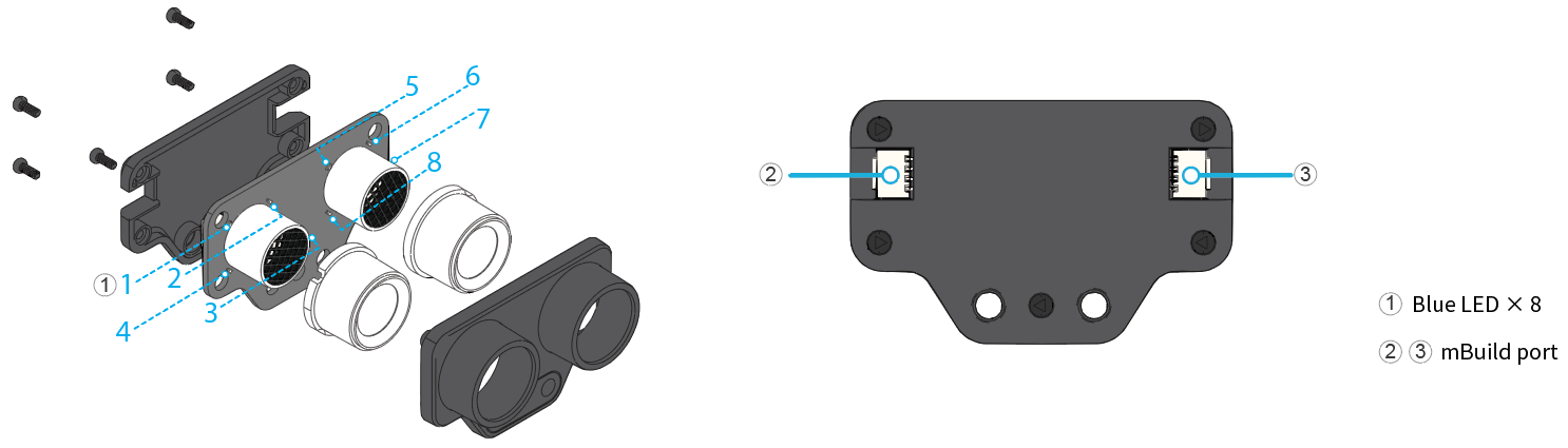
Ultrasonic sensor comparison
| mBot2 | mBot | |
|---|---|---|
| Plastic casing to improve the durability and quality | Yes | No |
| Built-in chip to improve the operation stability | Yes | No |
| Blue LED | ||
| (additional function) | 8 | 0 |
Quad RGB Sensor
Quad RGB Sensor is a new design based on the line-following sensor. It uses visible light as fill lights, which significantly reduce the interference of ambient light. In addition, it provides the function for recognizing colors. With four light sensors, it can support more programming scenarios.
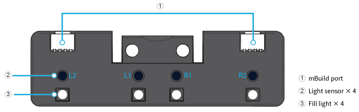
Line-following sensor comparison
| mBot2 | mBot | |
|---|---|---|
| Plastic casing to improve the durability and quality | Yes | No |
| Line-following sensor | 4 | 2 |
| Color sensor | 4 | |
| (also serve as line-following sensors) | No | |
| Light sensor | 4 | |
| (also serve as line-following sensors) | No | |
| Fill light | Visible light | IR light |
| Ambient light calibration to significantly reduce the interference of ambient light | Yes | No |
Chassis
We have optimized the chassis to ensure that it complies to the hole spacing specifications of the mechanical parts. In addition, we have increased the number of through-holes.
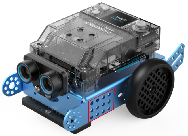
More information
mBot2 Shield CyberPi Operation Guide mBot2 Operation Guide
[Detailed Example] Programming mBot2 with the Mobile mBlock 5 App
This page describes how to write a simple obstacle avoidance program for mBot2 with the mBlock 5 app on your smart device.
Before you start, make sure that you've got:
| or
A tablet or smart phone |
mBot2
If you haven't completed the building of mBot2, refer to "Build mBot2" to build it first. |
| --- | --- |
:::info Note: The smart device described on this page is a tablet, and you can use the mBlock 5 app on smart phones in the same way. :::
1. Download the mBlock 5 app on the tablet
(Skip this step if you have already downloaded the mBlock 5 app.)
Use the tablet to scan the following QR code:
Alternatively, search for mBlock in app stores to download it.
2. Connect mBot2 to the mBlock 5 app
(1) Enable the Bluetooth function on the tablet.
(2) Power on mBot2.
(3) Tap to open the mBlock 5 app.
(4) Tap "Coding", and tap "+" on the page that appears.
(5) In the sprite library, choose "Devices" > "CyberPi" and tap "√".
(6) Tap the CyberPi setting icon and then tap "Connect" on the device setting page that appears.
(7) Place the tablet close to mBot2.
mBlock 5 automatically searches for and connects to mBot2.
After the connection is complete, a voice message is played, indicating that the connection is successful.
3. Start to write the program
(1) Tap "Back to coding".
(2) Add the extensions required in the obstacle avoidance program.
To avoid obstacles, mBot2 uses its ultrasonic sensor 2 to detect obstacles in its way and then respond to them by using the motors and wheels connected to mBot2 Shield. Therefore, you need to add the mBot2 and Ultrasonic Sensor 2 extensions.
Add them as follows:
a. Tap + Extension at the bottom of the blocks area, and then tap + Add under mBot2 on the Extension Center page that appears.
b. Tap + Extension at the bottom of the blocks area, and then tap + Add under Ultrasonic Sensor 2 on the Extension Center page that appears.
After the extensions are added, you can find the blocks in the blocks area.
(3) Set the programming mode to "Upload".
Live: In this mode, you can view the program execution effect in real time, which facilitates the debugging of the program. In this mode, you must keep mBot2 connected to mBlock 5. If they are disconnected, the program cannot be executed.
Upload: In this mode, you need to upload the compiled program to mBot2. After being successfully uploaded, the program can still run properly on mBot2 when it is disconnected from mBlock 5.
(4) Drag the blocks required to the scripts area.
a. First, define the event for triggering the execution of the obstacle avoidance program. For example, trigger the program by pressing button B.
Tap the Events category, drag the block when button () pressed to the scripts area, and tap the drop-down list box to select button B.
b. Define how many times the program is to be executed. For example, keep executing the program after it is triggered.
Tap the Control category and drag the block forever to the scripts area.
c. Define the specific conditions for avoidance and how mBot2 responds to an obstacle.
Define the condition For example, mBot2 starts to avoid an obstacle when it is 9cm or less away from mBot2; and mBot2 keeps moving forward when no obstacle is found or an obstacle is more than 9cm away from it.
Tap the Control category and drag the block if () then () else () to the scripts area.
The condition involves the operation of distance.
Tap the Operators category and drag the block () > () to the scripts area and put it into the condition block.
Tap the value 50 to change it to 9.
Tap the Ultrasonic Sensor 2 category and drag the block ultrasonic 2 () distance to an object (cm) to the scripts area and put it into the operation block.
Define the responses
When an obstacle is more than 9cm away from mBot2, mBot2 keeps moving forward.
Tap the mBot2 Chassis category and drag the block () at () RPM to the scripts area and put it into the condition block.
When an obstacle is 9cm or less away from mBot2, mBot2 turns left.
Drag the block () at () RPM for () secs to the scripts area, put it into the condition block, and tap the drop-down list box to select turns left.
Now, a simple obstacle avoidance program is completed.
4. Upload the program to mBot2
:::info Note: The program you upload will replace the last program you execute on mBot2. :::
Tap the Upload icon, wait till the uploading is complete, and tap OK.
5. Execute the program
Press button B on CyberPi.
mBot2 starts to move forward and detects obstacles. When an obstacle is found and it's 9cm or less away from mBot2, mBot2 turns left for one second and then moves forward.
:::tips Tips:
- You can change the parameter values on the blocks (such as changing the distance threshold or responses) or add more conditions to compile your own obstacle avoidance programs.
- You can also compile other programs (such as a line following program) in a similar way. :::
[Detailed Example] Program mBot2 with mBlock 5 on Your PC
This page describes how to write a simple obstacle avoidance program for mBot2 with the mBlock 5 client on your PC.
Before you start, make sure that you've got:
| or
A computer |
mBot2
If you haven't completed the building of mBot2, refer to "Build mBot2" to build it first. |
| --- | --- |
1. Download and install mBlock 5 on your PC
(Skip this step if you have already downloaded and installed mBlock 5 on your PC.)
(1) Go to https://mblock.makeblock.com/en-us/download/ to download mBlock 5 to a local disk.
Download the version compatible to the system running on your PC.
(2) Double-click the software you've downloaded to install it.
Click Yes when the system asks you "Do you want to aloow this app to make changes to your device?" and click to install drivers if prompted.
2. Connect mBot2 to mBlock 5
(1) Double-click the mBlock 5 icon on your PC to open it.
(2) Use a Micro USB cable (Type-C) to connect mBot2 to your PC, and power on mBot2.
(3) Click "+ add" on the "Devices" tab, select "CyberPi" in the device library, and click "OK".
:::info
Note: mBlock 5 displays the most frequently used device by default, and you can neglect it or delect it before adding a device.
:::
(4) Click "Connect" to connect CyberPi to mBlock 5.
3. Add the extensions required in the obstacle avoidance program
To avoid obstacles, mBot2 uses its ultrasonic sensor 2 to detect obstacles in its way and then respond to them by using the motors and wheels connected to mBot2 Shield. Therefore, you need to add the mBot2 and Ultrasonic Sensor 2 extensions.
(1) Add the "mBot2" extension.
(2) Add the "Ultrasonic Sensor 2" extension.
After adding the extensions, you can find the blocks in the blocks area.
4. Start to write the program
(1) Set the programming mode to "Upload".
Live: In this mode, you can view the program execution effect in real time, which facilitates the debugging of the program. In this mode, you must keep mBot2 connected to mBlock 5. If they are disconnected, the program cannot be executed.
Upload: In this mode, you need to upload the compiled program to mBot2. After being successfully uploaded, the program can still run properly on mBot2 when it is disconnected from mBlock 5.
(2) Drag the blocks required to the scripts area.
a. First, define the event for triggering the execution of the obstacle avoidance program. For example, trigger the program by pressing button B.
Click the Events category, drag the block when button () pressed to the scripts area, and click the drop-down list box to select button B.
b. Define how many times the program is to be executed. For example, keep executing the program after it is triggered.
Click the Control category and drag the block forever to the scripts area.
c. Define the specific conditions for avoidance and how mBot2 responds to an obstacle. Define the condition For example, mBot2 starts to avoid an obstacle when it is 9cm or less away from mBot2; and mBot2 keeps moving forward when no obstacle is found or an obstacle is more than 9cm away from it.
Click the Control category and drag the block if () then () else () to the scripts area.
The condition involves the operation of distance.
Click the Operators category and drag the block () > () to the scripts area and put it into the condition block.
Click the value 50 to change it to 9.
Click the Ultrasonic Sensor 2 category and drag the block ultrasonic 2 () distance to an object (cm) to the scripts area and put it into the operation block.
Define the responses
When an obstacle is more than 9cm away from mBot2, mBot2 keeps moving forward.
Click the mBot2 Chassis category and drag the block () at () RPM to the scripts area and put it into the condition block.
When an obstacle is 9cm or less away from mBot2, mBot2 turns left.
Drag the block () at () RPM for () secs to the scripts area, put it into the condition block, and click the drop-down list box to select turns left.
Now, a simple obstacle avoidance program is completed.
5. Upload the program to mBot2
:::info
Note: The program you upload will replace the last program you execute on mBot2.
:::
Click Upload and wait till the uploading is complete.
:::info
**About program overriding **
You can find two program categories on CyberPi, namely Preset and My programs. Choose Switch Program and then pull the joystick to the left or right to switch betweem them.
An uploaded program can override a program only in My programs.
-
If you upload a program when you are running a preset program, the program you uploaded override Program1 in My programs. You need to enter My programs to find it and can press button B to run it.
-
If you upload a program when you are running a program in My Programs, the program you upload override the program you are running. For example, you upload a program when you are running Program2, Porgam2 is overridden by the program you upload.
To change the name of a program, see "How to change program names on CyberPi?" :::
6. Execute the program
Press button B on CyberPi.
mBot2 starts to move forward and detect obstacles. When an obstacle is found and it's 9cm or less away from mBot2, mBot2 turns left for one second and then moves forward.
:::tips Tips:
- You can change the parameter values on the blocks (such as changing the distance threshold or responses) or add more conditions to compile your own obstacle avoidance programs.
- You can also compile other programs (such as a line following program) in a similar way.
- To learn more from example programs, choose Tutorials > Example Programs on the menu bar of mBlock 5. :::
Pocket Shield Operation Guide
1. Know your Pocket Shield
Pocket Shield provides the following functions for CyberPi:
1.1 Supplying power
Pocket Shield is equipped with a rechargeable 800 mAh Li-ion battery that can be charged while supplying power for CyberPi.
The following table describes the charging and power supplying of Pocket Shield.
| Battery life Supplies power for CyberPi with loads, such as servos and motors, in common application scenarios. | More than 4 hours | | --- | --- | | Upper limit of battery life CyberPi operates in the sleep mode with the screen off. | More than 24 hours | | Time to fully charge the battery | About 1 hour |
:::info Note: The charging is slower at the beginning if the battery of Pocket Shield runs too low. The battery life of Pocket Shield may vary according to the operating of CyberPi, the loads it bears, or the use of the battery, as described in the following:
- Pocket Shield is used to drive motors, servos, LED strips, or third-party sensors.
- CyberPi is used to perform high-frequency wireless communication or the LEDs on it are lit up at high brightness for a long time.
- After the lithium-ion battery is charged and discharged for a large number of times, its capacity may decrease. :::
1.2 Extending functions
Pocket Shield provides two types of ports, namely 2-pin and 3-pin ports, which are designed with an anti-plug mechanism and the pin spacing of 2.54 mm. The 2-pin ports can be used to connect motors and the 3-pin ones can be used to connect servos or LEDs strips.
In addition, you can connect third-party sensors to Pocket Shield through DuPont wires.
Supported motors
Pocket Shield drives DC motors, water pumps, and fans at a higher voltage (5V) to provide better operation performance, including the torque and rotational speed. This may, however, cause Pocket Shield to fail to drive motors that work well with the earlier products we have developed.
The earlier products we have developed, such as mBot, drive motors at the voltage of 3.7V. The start current of a motor becomes higher when it is driven at a higher voltage, and therefore the start current of such motors may exceed the current limit designed for the protection of the driving chip of Pocket Shield.
To ensure compatibility, refer to the motor driving specifications of Pocket Shield when purchasing motors for it or purchase the motor pack we are going to launch for Pocket Shield.
| Pin spacing | 2.54 mm |
|---|---|
| Output voltage | 5 V |
| Operating current | < 1.2 A |
| Max. transient current | 2.4–4.8 A |
Supported servos
Servos developed by Makeblock are recommended.
Pocket Shield is compatible with third-party servos, but slight angle deviations may occur due to the component protocols.
| Pin spacing | 2.54 mm |
|---|---|
| Operating voltage | 5 V |
| Operating current | < 1.6 A |
Supported LED strips
The digital servo ports can also be used to connect LED strips.
LED strips developed by Makeblock are recommended.
Pocket Shield is compatible with third-party LED strips, but control exceptions may occur due to the definition differences of high and low levels in the component protocols.
Supported third-party sensors
The output voltage of Pocket Shield is 5 V. It is well compatible with Arduino digital and analog sensors and output modules. The operating voltage of micro:bit sensors is 3.3 V, and therefore Pocket Shield may not work well with them.
2. Add the Pocket Shield extension
Click + extension and then click + Add in the extension center to add the Pocket Shield extension.
The following blocks are provided in the Pocket Shield extension, indicating the functions that have been developed.
Among them, the following ones are developed for third-party sensors.
3. Python APIs
For information about the APIs for Pocket Shield, see "APIs for Pocket Shield" in the Python API Documentation for CyberPi.
4. Online help
After-sales services and technical support
If you encounter any product quality problems or find any parts missing or damaged when you open the package, or if you need any technical support, contact us for after-sales services through:** ** support@makeblock.com (Service hours: 9:00–12:00 & 14:00–18:30 from Monday to Friday)
Feedback and suggestions
Should you have any feedback or suggestions on CyberPi, contact our R&D team through: cyber.list@makeblock.com
5. FAQs
How long does it take to fully charge Pocket Shield?
Within two hours. It can be charged faster when powered off.
Can I use CyberPi and Pocket Shield to participate in the Arduino competition?
Working with Pocket Shield, CyberPi supports Arduino modules and parts, but it is a new-generation open-source device designed based on China-made chips instead of Arduino hardware.
CyberPi is designed with high compatibility and can communicate with Arduino main control boards through serial ports or Bluetooth. Therefore, you can use CyberPi as an input or output part for Arduino main control boards to implement powerful and abundant AI and IoT functions in your Arduino projects.
What if the voltage of pins can't be properly obtained?
This is caused by the errors that occur during the switching of pin modes. A new firmware version will be released in August to solve this problem. At present, you can refer to the following program to switch the pins to the correct states to ensure proper voltage output.
How to update the firmware?
- Connect Pocket Shield to CyberPi through the CyberPi port.
- Use a Type-C USB cable to connect CyberPi to your PC, and turn on Pocket Shield.
- Open the mBlock 5 PC client or webpage, connect CyberPi to mBlock 5, and set the programming mode to Live.
If mBlock 5 prompts you to update the firmware, as shown in the following figure, you need to update the firmware of CyberPi or Pocket Shield.
Click Update. mBlock 5 updates CyberPi or Pocket Shield to the latest firmware version.
6. More information
CyberPi Operation Guide Pocket Shield Operation Guide CyberPi Series User Manual Python API Documentation for CyberPi mBlock 5 Online Help mBlock-Python Editor Online Help
Operation Guide of the "Display +" Extension for CyberPi
Foreword
Hello, I'm Alex Yu, the product manager of CyberPi. I'm glad to introduce the Display + extension to you. It is the key feature update in iteration 003 of CyberPi.
This page describes the details about how to use the Display + extension and provides some example programs, both simple and complicated ones. The content on this page will be continuously updated and improved to help you use the Display + extension more efficiently.
Notice
- The Display + extension is available only for firmware 003 or later of CyberPi. You can update the firmware of CyberPi in OTA mode or on mBlock 5.
- Currently, CyberPi supports only mBlock 5 on the web. The PC client and mobile app will be launched around the end of September.
- The current Display + extension“ is a beta version and provides only some basic functions. Exceptions may occur when you use it, and its design still needs some improvement. Contact us if you have any suggestions or feedback on the improvement of this extension.
- Efforts will be made to ensure the compatibility of later official versions with projects created in the earlier versions, but the compatibility can't be ensured.
- In the short term, this extension will support only the Upload mode and MicroPython programming due to the complexity of object-oriented programming.
Use the "Display +" extension
Add the Display + extension
After connecting CyberPi to mBlock 5, click + extension at the bottom of the blocks area, and then click + Add at the bottom of Display +.
After adding the extension, you can see the Sprites and Doodle blocks.
The Display + extension extends the programmable functions of CyberPi's screen. With this extension, you can design apps, games, and more complicated charts on CyberPi.
The Display + extension adopts the concept of object-oriented programming (OOP), and therefore, when you use this extension for programming, you need to define an object first.
The following figure describes the three basic steps for using the Display + extension for programming.
Create a sprite
Create a variable in the Variables category, and then define the variable as a sprite.
:::tips **Tips: **You can name a variable to be defined as a sprite in the format of s__XXX_ to distinguish it from an ordinary one_._ For example, s_text indicates a text variable to be defined as a sprite, and text indicates an ordinary text variable. :::
- Select the Variables category and click Make a Variable.
- In the New Variable dialog box that appears, enter the variable name and click OK.
The created variable and its related blocks appear in the Variables category.
- Set the value of the created variable and define it as a sprite through blocks, as shown in the following example.
:::tips Summary: The steps for creating a sprite are as follows: creating a variable -> assigning a value and defining it as a sprite -> performing redering to display the sprite
Note that the sprite can be displayed only when you use the force rendering block. :::
If a variable is defined as a sprite, you can no longer perform arithmetic operations on it because data of the sprite type does not support arithmetic operations. Errors may be reported if you do.
For example, an error is reported when you execute the following program.
Types of sprites
We have defined multiple types of sprites to facilitate your creation of projects. Generally, you can use the following blocks to define sprites.
The following table describes the currently available types of sprites.
| Type | Block | Description |
|---|---|---|
| Matrix | | Defines a matrix image as a sprite |
| Tips: We have restricted the aspect ratio of matrix images for MicroPython programming, allowing you to create larger images, for example, a 128 × 128 (pixel) image. | ||
| Text | | Defines a text as a sprite |
| Icon | | Defines a preset icon as a sprite |
| QR code | | Defines a QR code as a sprite |
| Doodle | | Defines a sketch as a sprite |
| Tips: The Doodle blocks simulate the structures of Turtles drawing, which work best when you use them to draw geometric figures. |
Modify parameters for sprites
You can modify the parameters for a sprite through blocks or APIs. The following figure shows the currently available parameters for sprites.
| Parameter | Block | Description |
| --- | --- | --- |
| Appearance | | The appearance of the sprite depends on the blocks set sprite ( ) to ( ) and sprite ( ) flips ( ).
|
| Anchor point | | The anchor point determines the origin of the sprite and its center of rotation. |
| Coordinates | | The coordinates determine the position of the sprite. You can move a sprite by changing its coordinates. |
| Direction angle | | The direction angle determines the direction the sprite faces. You can rotate a sprite by changing its direction angle. |
| Scaling | | This block determines the ratio of the to-be-displayed sprite to the original size of the sprite. |
| Color | | You can put a color layer over a sprite. For example, you can change the color of a text sprite from white to red. |
| Display setting | | This block can be used to show or hide a sprite. |
| Layer | | These blocks can be used to place a sprite on the specified layer. |
:::tips Tips: After a sprite is created, its parameters are set to the default values. When it is changed by using the block set sprite ( ) to ( ), all the other properties remain, except the reflecting effect. The reflecting effect is part of the appearance of the sprite. :::
Rendering
After modifying the properties of a sprite, you need to perform rendering on it to make the new properties take effect, that is, use the block force rendering.
Each time of rendering is similar to generate a frame in animation. Using the force rendering function properly can make better use of the hardware performance.
CyberPi can execute multiple threads simultaneously, and therefore, you can write a thread to implement timed rendering.
The following shows an example.
The implementation of the rendering mechanism may be different from other graphical programming logic. We have also tried to design an automatic rendering mechanism but haven't released it due to its stability.
Block help
When you use the Display + extension on mBlock 5, you can right-click a block and click Help that appears to get the help information provided for it.
Alternatively, you can open Display+ Block Help to read the help information provided for all the blocks of the Display+ extension. Display+
Others
Detection
Some blocks are designed for users to obtain the status information of sprites. The following describes some of these blocks.
To obtain status information of a sprite, use:
To determine whether a sprite touches another one or the edge of the screen, use:
To determine the background color of the screen, use:
Background color setting
To set the color of the background, use:
:::info
Note: After setting the color, you need to use the block force rendering to make the setting take effect.
:::
Example programs
Aircraft War
In this example, detection of touching and self-defined matrix images are used. Aircraft War V1.4.rar
Fun with Arithmetic
In this example, the function for defining sprites is used to implement the alternation of questions and answers. Fun with Arithmetic V3.1.rar
FAQs on CyberPi
Hardware
Q1: What can I do if I find there's something wrong with CyberPi?
If there's something wrong with CyberPi, provide the following information to obtain the after-sales service:
- Serial number, which you can find on the product packaging
- Firmware version of CyberPi, which you can find by entering the CyberOS and choose Settings > Update
- Where and when you purchased CyberPi, and the receipt
- Photo or video that can show what is wrong with CyberPi
A one-year warranty service is provided for CyberPi. For details, see CyberPi Warranty Assurance.
Q2: What is the maximum recording duration of CyberPi?
About 10 senconds
Q3: Can I divide a recording of CyberPi into multiple ones?
No, no dividing function is provided.
Q4: Can I connect CyberPi to a 5G network through Wi-Fi?
No, 5G network is not supported.
Q5: Does CyberPi have a MAC address? If yes, how can I obtain it?
Yes, as any of the devices that can be connected to the Internet, CyberPi has a MAC address. You can obtain it as follows:
- Connect CyberPi to mBlock 5.
For details, see "Add and connect CyberPi."
- Choose the Sensing category, select MAC address from the battery level(%) drop-down list box, and select the check box on the left of the block.
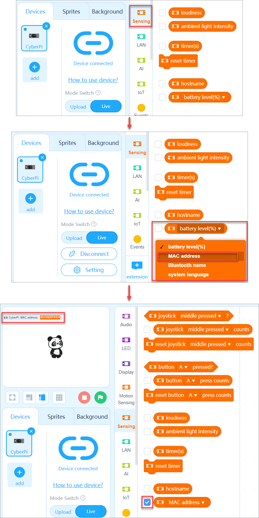 You can see the MAC address of your CyberPi on the stage.
Q6: How do I set up the Wi-Fi connection for CyberPi?
After connecting CyberPi to mBlock 5 (For details, see "Add and connect CyberPi."), you can set up the Wi-Fi connection for CyberPi in one of the following ways:
- Use the Setting function.
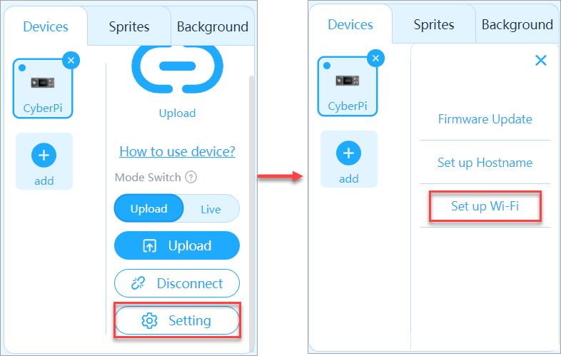 Enter the available Wi-Fi name and password, and click OK.
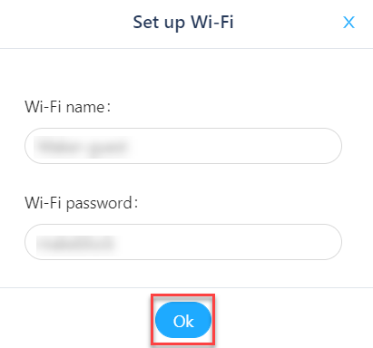 Every time when you start CyberPi, it attempts to connect to the Internet through the Wi-Fi you set.
- Use the Wi-Fi setting block
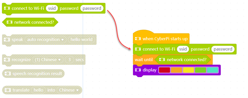 Upload the program to CyberPi.
Every time when you execute this program, CyberPi attempts to connect to the Internet through the Wi-Fi you set.
Upload the program to CyberPi.
Every time when you execute this program, CyberPi attempts to connect to the Internet through the Wi-Fi you set.
Q7: Is the Wi-Fi function of CyberPi available only in Live mode? Can I use it in Upload mode?
No, the Wi-Fi function of CyberPi is available only in Upload mode, and if you use the Wi-Fi setting block to set the Wi-Fi connection, you need to upload the program to CyberPi.
Q8: What is the maximum number of devices that can be connected on a local area network (LAN ) I create for CyberPi?
64 devices.
:::info **Note: **If many electronic devices operate around, the communication between the devices on the LAN may be affected, and therefore the maximum number may vary according to the ambient environment. :::
Q9: How do I charge my Pocket Shield?
- Connect Pocket Shield to CyberPi through the CyberPi port.
- Use a Type-C USB cable to connect CyberPi to your PC.
If you turn on the power switch of Pocket Shield, you can use it while charging it; and if you don't turn
on the power switch, the charging can be completed faster.
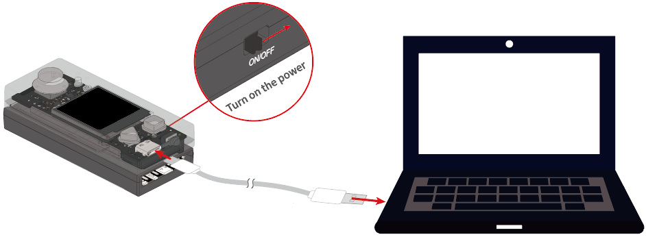 :::info
Note:
:::info
Note:
- You can also use a standard USB multi-port socket commercially available to charge multiple Pocket Shields simultaneously, but don't use portable charging power supplies on the market because their charging voltage may not meet the requirements of Pocket Shield.
- Quick chargers are also not recommended. (The charging voltage of some quick chargers may be higher than 5 V, which may damage your Pocket Shield.) :::
Q10: How long does it take to fully charge Pocket Shield and how long can it be used?
It takes about 1-2 hours to fully charge Pocket Shield. It can be charged faster when powered off. Once fully charged, it can supply power for CyberPi for about 4 hours.
Q11: How do I use S1, S2, M1, and M2 ports on Pocket Shield?
The ports S1 and S2 can be used to connect servos or LEDs strips. M1 and M2 can be used to connect mBuild motor and 6V TT motors.
Software
Q12: How do I update the firmware of CyberPi?
You can update the firmware of CyberPi in either of the following ways:
Using mBlock 5
- Use a Type-C USB cable to connect CyberPi to your PC.

- Open the mBlock 5 PC client or webpage, connect CyberPi to mBlock 5, and set the programming mode to Live.
If mBlock 5 prompts you to update the firmware, as shown in the following figure, you need to update the firmware of CyberPi.
Click Update. mBlock 5 updates CyberPi to the latest firmware version.
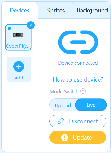
In OTA mode
- Set the Wi-Fi connection for CyberPi. For details, see "Q6: How do I set up the Wi-Fi connection for CyberPi?"
- Enter CyberOS.
- Choose Settings > Update.
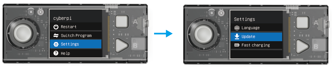 CyberOS automatically checks for the latest firmware version and prompts you to update the firmware if the current version is not the latest one.
Q13: Do I have to set up the Wi-Fi connection for CyberPi before using the LAN function?
No, CyberPi can communicate with another device on the same LAN without connecting to the Internet through Wi-Fi, which is different from Halocode that needs to connect to the Internet through Wi-Fi before communicating with another Halocode on the same LAN.
Q14: How do I use the "insert code" block in the "Control" category in Upload mode?
You can enter a micro-python statement, for example, cyberpi.console.print("hello"),** **in the block.
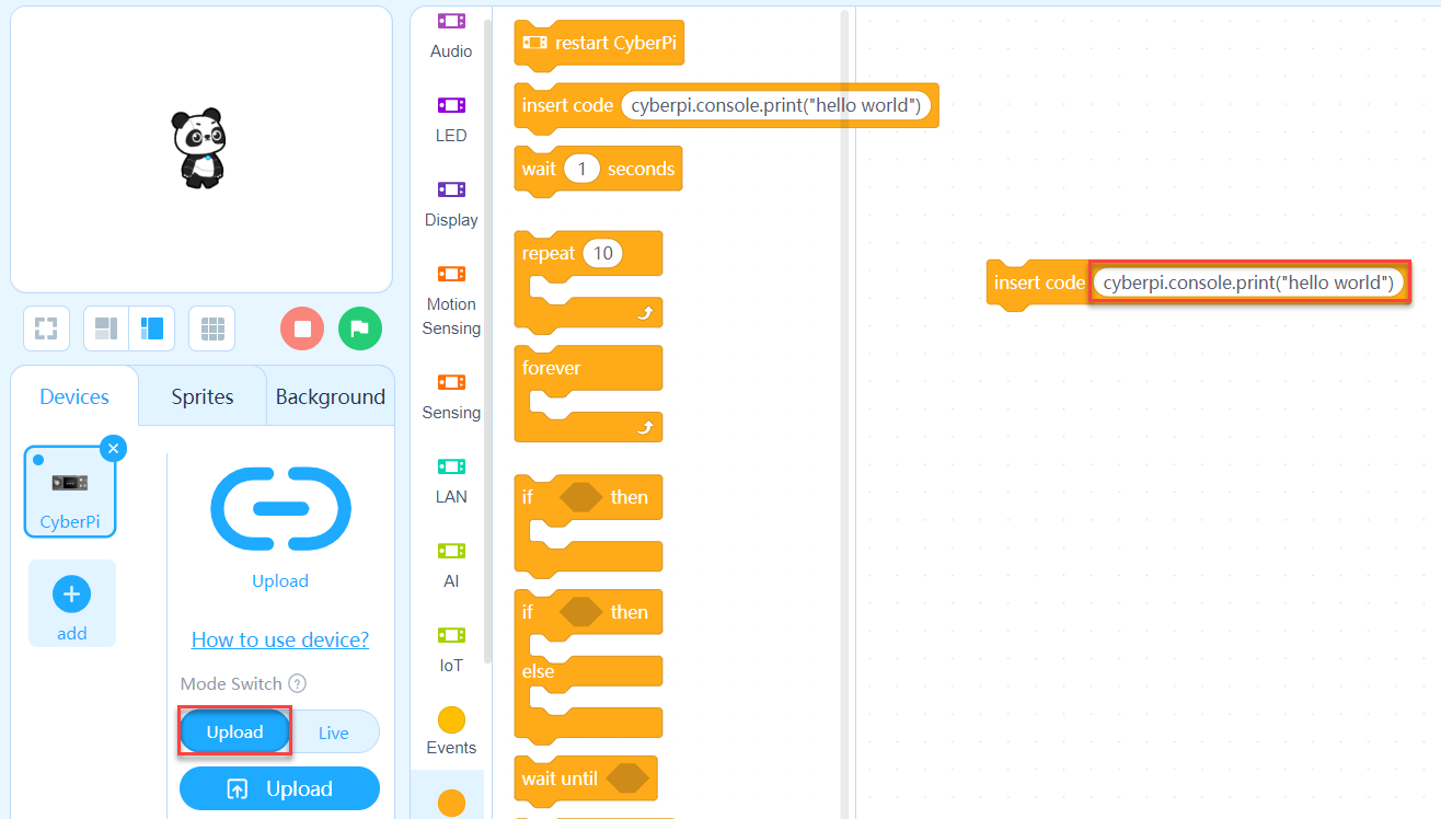
Q15: With the Display+ extension, when I change the color of a sprite, the color of the previously displayed sprite also changes. Is this what it's supposed to be?
Yes. Currently, color coded display is not available.
Q16: With the Display+ extension, when I change the size of a sprite, the size of the previously displayed sprite also changes. Is this what it's supposed to be?
Yes. Currently, it can't display the sprites in different sizes.
Q17: What are the upper and lower limits of figures in a line chart?
0–100
Q18: Can I differentiate multiple pieces of data in a line chart by color?
Yes, you can.
Q19: What is the maximum number of pieces of data that can be included in a line chart?
There is no limit. The amount depends on the RAM of the operating system.
Q20: What are the upper and lower limits of figures in a bar chart?
0–100
Q21: Can I differentiate multiple pieces of data in a bar chart by color?
Yes, you can.
Q22: What is the maximum number of pieces of data that can be included in a bar chart?
A maximum of 24 pieces.
FAQs on mBot2
Change history
- 2021/6/29: initial release
Hardware
1. Are the encoder motors used on mBot2 the same as those on mBot Ranger?
Yes.
2. Can I remove CyberPi from the mBot2 shield and use it as a remote control?
CyberPi is the main control board of mBot2. If you take it off the mBot2 shield, mBot2 can't move any more. If you've got multiple CyberPis, however, you can fit one the mBot2 shield, and then use a second one as a remote control to control mBot2 based on its main control board, that is, the CyberPi connected to the mBot2 shield.
3. What is the capacity of the built-in battery of mBot2?
2500 mAh
4. How long does it take to fully charge mBot2 and how long can mBot2 operate after it is fully charged?
| Battery life Supplies power for mBot2 with loads, such as servos and motors, in common application scenarios. | 2.5 hours–5 hours When mBot2 keeps moving or keeps operating with loads: 2.5 hours | | --- | --- | | Upper limit of battery life mBot2 operates in the sleep mode with the screen off. | More than 24 hours | | Time to fully charge the battery | 1 hour–2 hours |
5. Can mBot2 operate without CyberPi?
No, the mBot2 shield can't work without CyberPi, its main control board. You need to program and control mBot2 through CyberPi.
6. Does the ultrasonic sensor 2 used on mBot2 transmit and receive signals?
Yes, the eye-shaped part on the left transmits signals, and the one on the right receives signals. For details, see Ultrasonic Sensor 2.

7. What is the detection range of the ultrasonic sensor 2 used on mBot2?
Detection range: 5–300 cm Detection error: ±5%
8. Can I change the light color of the LEDs on the ultrasonic sensor 2?
No, you can't. The LEDs can be lit up only in blue.
9. How many LEDs are provided on the ultrasonic sensor 2?
Eight programmable LEDs.
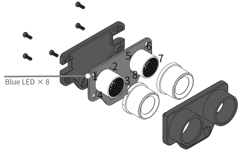
10. What can I do with the LEDs on the ultrasonic sensor 2?
You can program the ultrasonic sensor 2 to control how many LEDs are lit up and how bright they are.
11. What's the function of the quad RGB sensor?
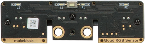 The quad RGB sensor integrates the functions of a color sensor, light sensor, and light following sensor. For details, see Quad RGB Sensor.
12. Are there any parts shared by mBot and mBot2?
| mBot | mBot2 | |||
|---|---|---|---|---|
| SKU | Name | SKU | Name | |
| Wheel hub | 83014 | Plastic Timing Pulley 90T (4-Pack) | 8.36.2053 | 90T Wheel |
| Tyre | ||||
| ※ | 87033 | Slick Tyre 64*16mm (4-Pack) | 8.70.6023 | 90T Tyre |
| Head-replaceable screwdriver | P2210001 | Cross&2.5mm HEX Screwdriver 2.0 | P2210001 | Cross&2.5mm HEX Screwdriver 2.0 |
| Mini wheel | 87010 | Mini Caster Wheel | 87010 | Mini Caster Wheel |
| Motor | ||||
| ※ | 81320 | TT DC motor 6V/200RPM | 81340 | 180 Optical Encoder Motor |
※ ① The screws used for installing the wheels can't be shared. ② The encoder motors used on mBot2 can't be used on mBot.
13. What is the maximum number of servos that can be connected to mBot2?
mBot2 provides four ports that can be used to connect servos, but you can connect it to more servos through the mBuild port.
14. What is the size of the screen on mBot2?
128 × 128 (pixels)
x-coordinate: 0–127
y-coordinate: 0–127
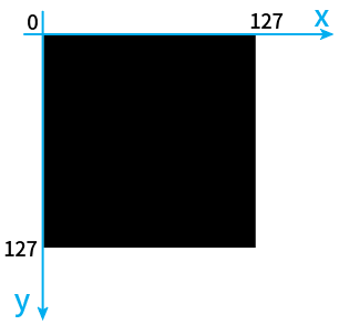
15. Is mBot2 equipped with a buzzer?
No, but its main control board, CyberPi, is equipped with a speaker that can function as a buzzer.
16. Can I use the speaker on CyberPi of mBot2 to play a MP3 file?
No, you can't.
The speaker on CyberPi can play only the default audio files or the sounds you record. Recorded sounds are stored in a RAM file. If you want to program mBot2 to play an MP3 file, you can usethe mBuild speaker module. It supports a maximum MP3 file of 16 MB.
For details, see Speaker.
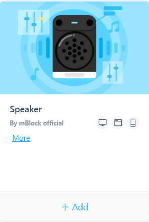
17. How to connect an LED strip to mBot2 and program it on mBlock 5?
If the LED strip you use is a 3-pin one, you can directly insert it into port S1 or S2 of the mBot2 shield. You can also use the LED strip module and LED driver developed by Makeblock.
After connecting an LED strip to the mBot2 shield, you can program it on mBlock 5 using the blocks shown in the following figure.
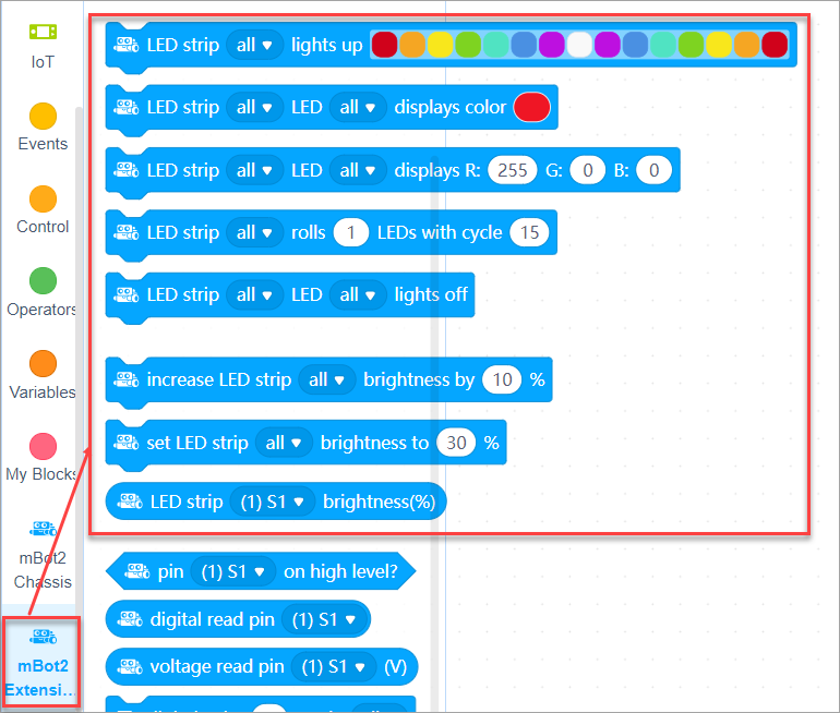
18. Is mBot2 equipped with an IR sensor?
No, it isn't. You can purchase an mBuild IR sensor to extend the functions of mBot2.
19. Can I use TT motors to connect to ports M1 and M2 on the mBot2 shield instead of the encoder motors installed on mBot2?
Yes, you can use TT motors instead of the encoder motors to get mBot2 moving.
20. After I update the firmware, the mBot2 or pocket shield doesn't work. What can I do?
Try performing the following steps:
-
Connect CyberPi to the mBot2 shield (pocket shield) and turn on the shield.
-
Use a USB cable to connect CyberPi to your PC and open the mBlock 5 web version.
-
On mBlock 5, add CyberPi from the device library. :::info Note: If a green icon is displayed in the upper-right corner of the CyberPi device image, click it to update the device to the latest version. :::
-
After you connect CyberPi to mBlock 5, mBlock 5 may prompt you to update the firmware (a message in yellow). Click it to update the firmware. :::info **Note: **It is recommended that you stay on the mBlock 5 page during firmware update. ::: After the firmware is updated, the mBot2 or pocket shield can work properly.
21. Are there any electronic versions of mBot2 building instructions?
Yes, you can visit mBot2 building to download an electronic version or view the 3D building demonstration online.
Software
1. How do I add mBot2 on mBlock 5?
- Open mBlock 5.
- Use a USB cable (Type-C) to connect mBot2 to your PC and turn on mBot2.

- Click + add on the Devices tab, select CyberPi in the device library, and click OK.

- Click Connect to connect CyberPi to mBlock 5.

- Enter the extension center and add the mBot2, Ultrasonic Sensor 2, and Quad RGB Sensor extensions one by one.
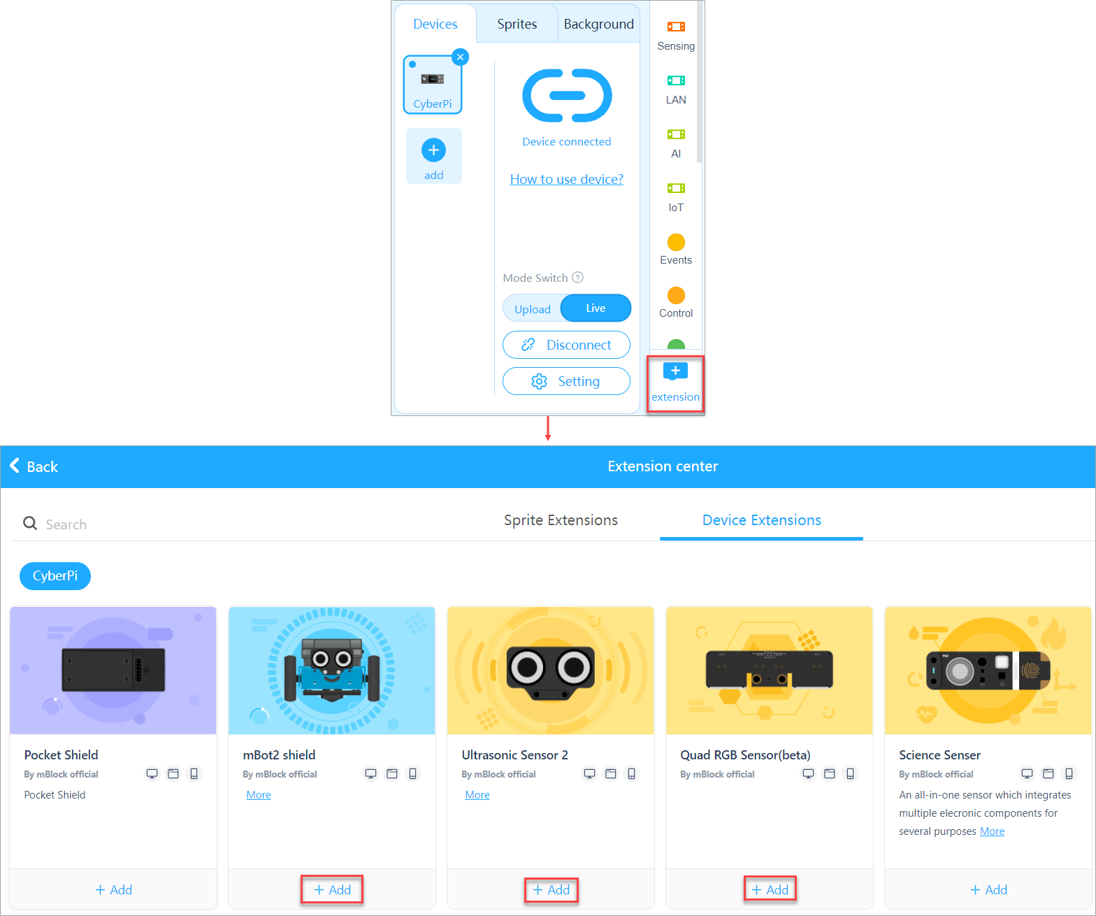 After adding the extensions, you can see the blocks available for mBot2.
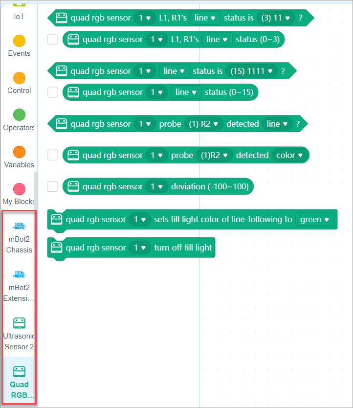
2. Are there any example programs provided for mBot2?
Yes, there are.
On mBlock 5, choose Tutorials > Example Programs and click mBot2 to view example programs provided for mBot 2.
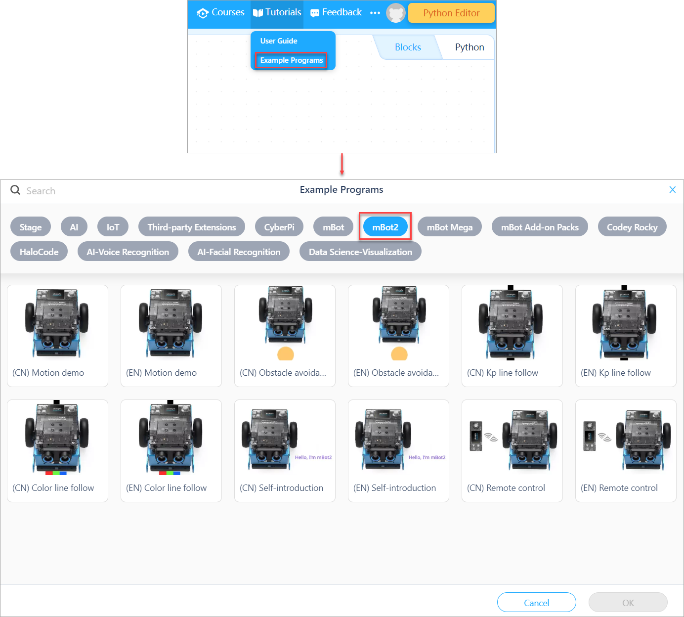
3. How to use the blocks? Is there any help information?
If you don't understand a block when using it, you can right-click it and click Help that appears.
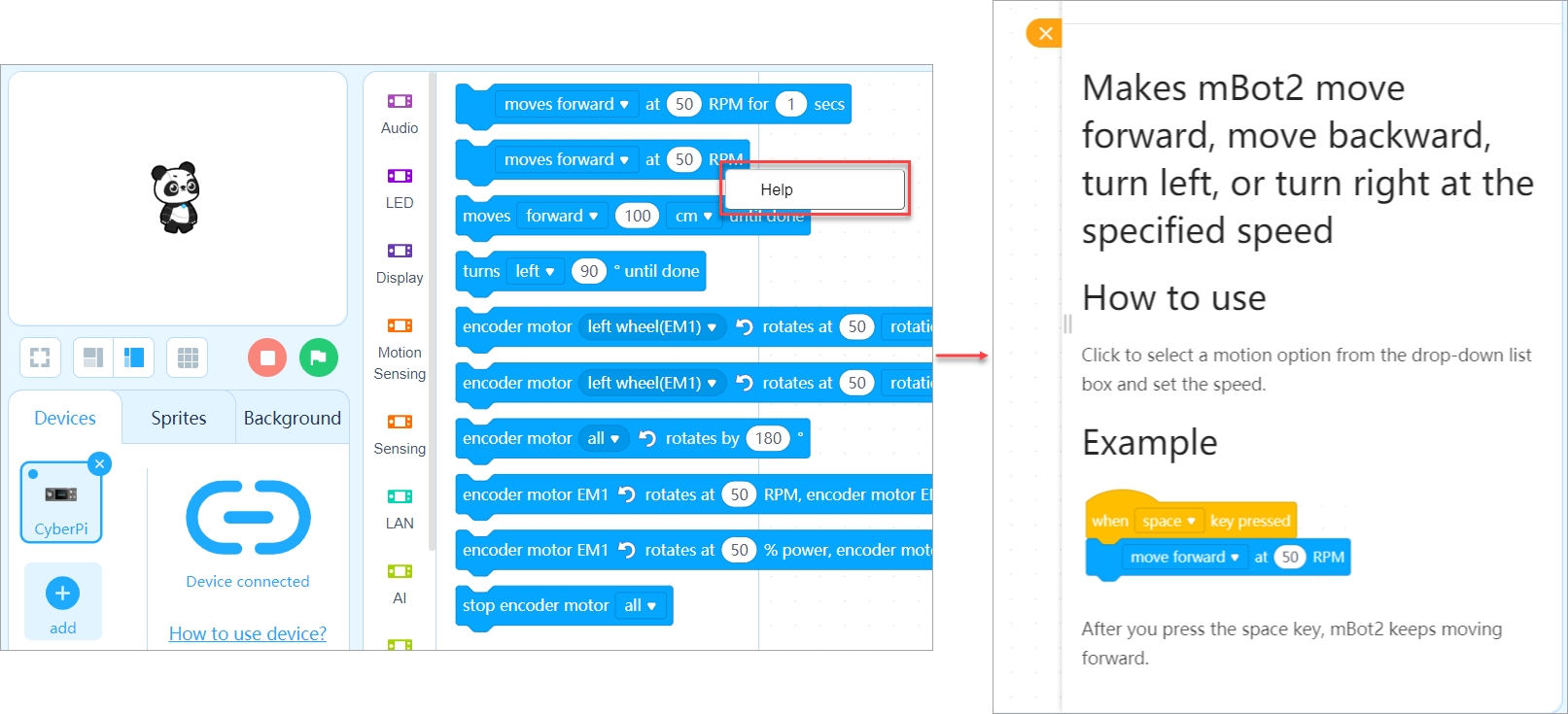
4. How do I learn Python programming?
You can learn Python programming in the following ways:
**Way 1: **
On the block-based editor of mBlock 5 (generally referred to as mBlock 5), translate blocks into Python statements.
In Upload mode, click the </> button on the right side.
The corresponding Python statements are shown.
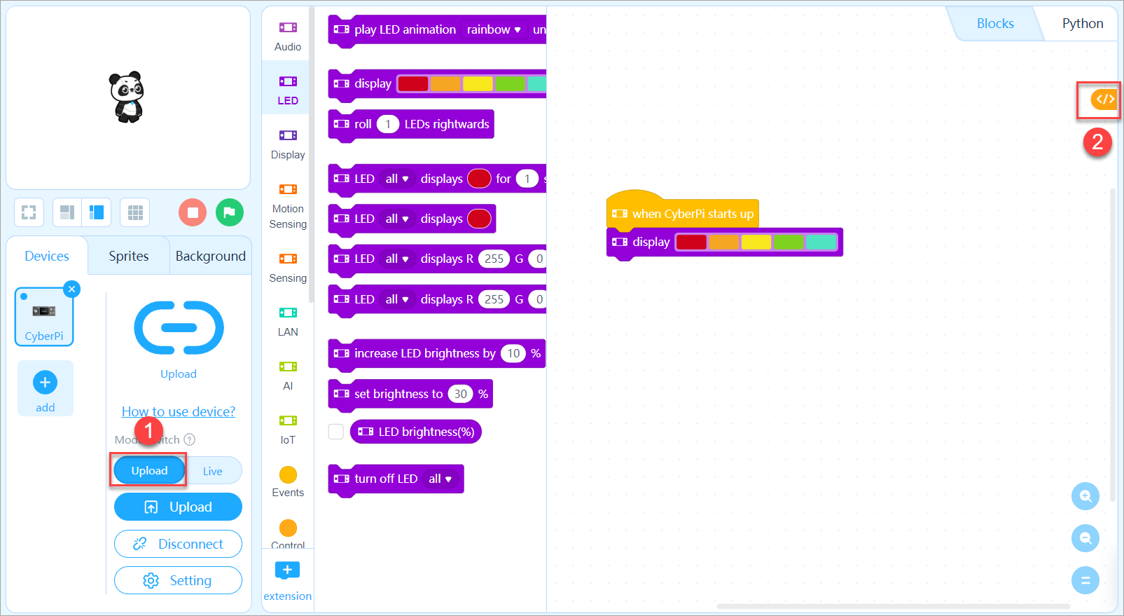
Way 2:
Use the mblock Python editor
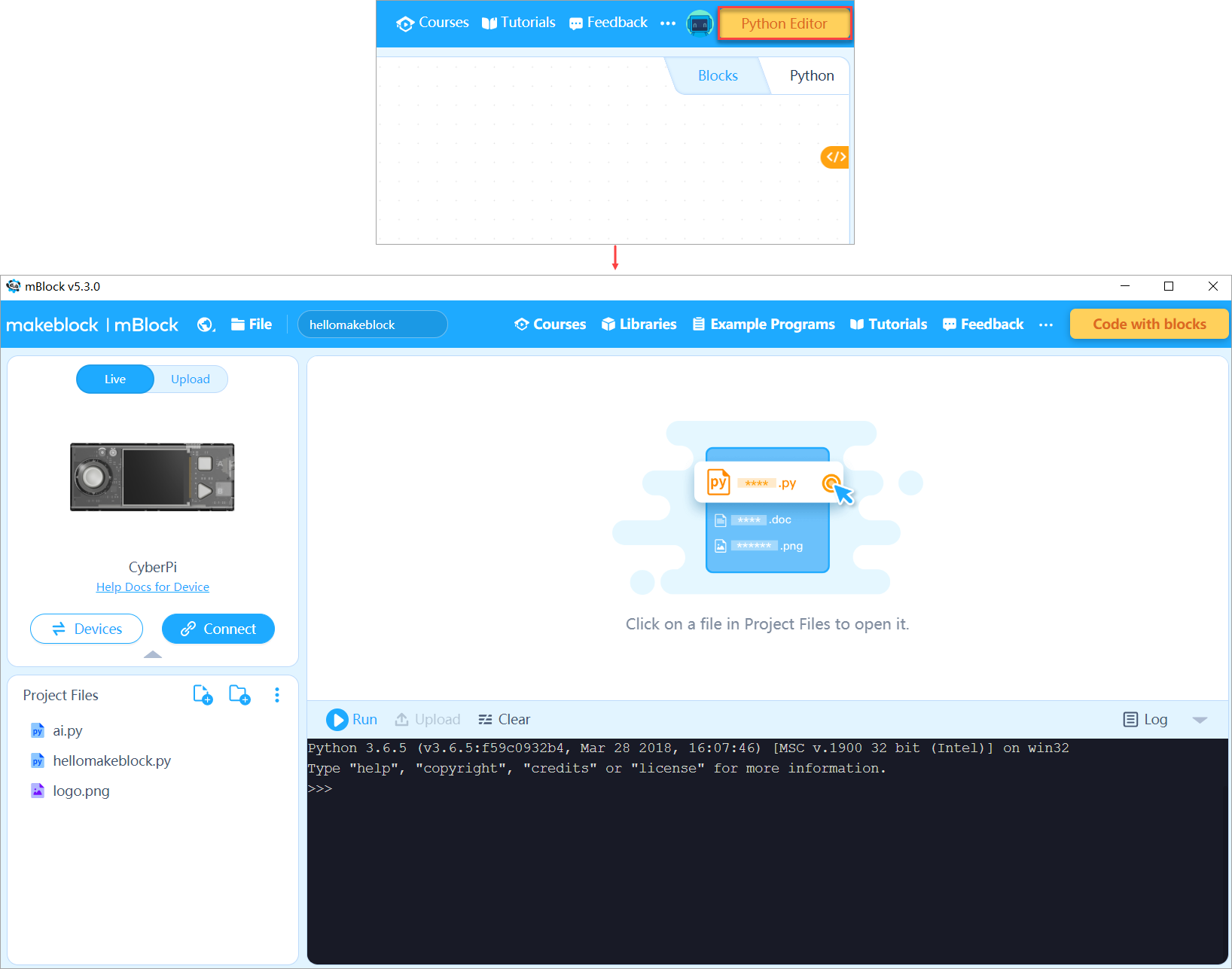
5. How do I find the libraries on the Python editor?
Choose Libraries on the toolbar.
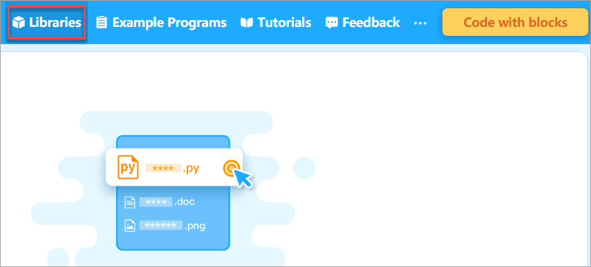 For details about how to install or uninstall Python libraries, see Install or Uninstall Python Libraries.
6. What are the Live and Upload modes on the Python editor?
- Upload: In this mode, only MicroPython programming is supported, and Python 3 libraries can't be used.
Advantage: After you upload a program to a robot, the robot can operate without connecting to a PC.
- Live: In this mode, Python 3 programming is supported, and therefore Python 3 libraries can be used.
Advantage: In this mode, you can execute programs online and thus check the programs immediately.
Exercise caution when you switch the programming modes.
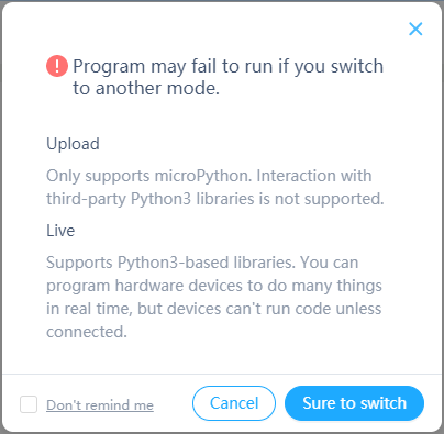
7. Can I use the Python editor to program other Makeblock products?
No. Currently, the Python editor can be used to program only CyberPi and mBot2.
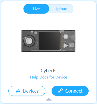
8. How do I connect mBot2 on the Python editor?
- Use a USB cable to connect mBot2 to your PC, or connect mBot2 to your PC through a Bluetootgh dongle.
- Click Connect.
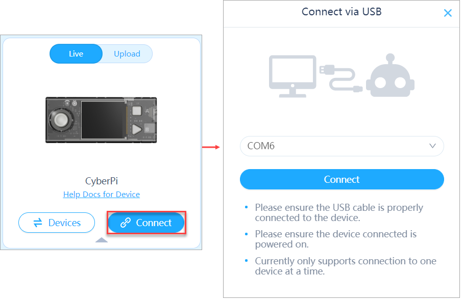 After mBot2 is connected, the button turns into green, indicating that mBot2 is connected.
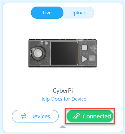
9. Besides English, does the Python editor support other languages?
Currently, the Python editor supports only simplified Chinese and English. It is recommended that you use the Python editor in English, which can help you learn Python code easier.
10. When I copy the Python code obtained on the block-based editor by translating blocks to the Python editor, mBot2 can't move any more, why?
For example, on the mBlock block-based editor:
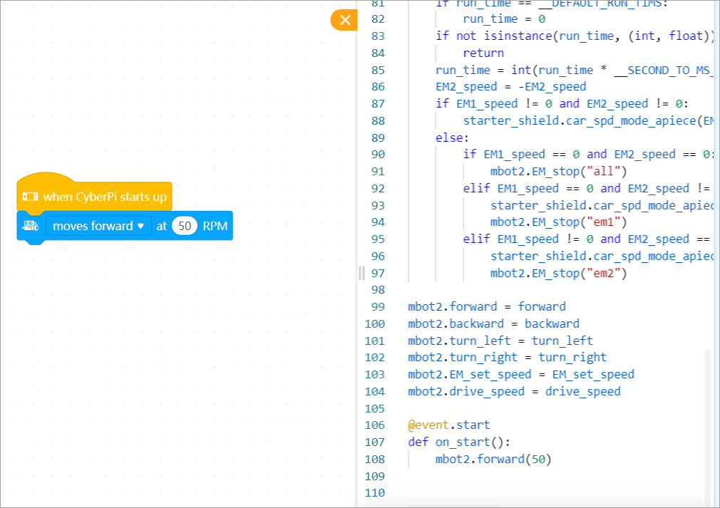
- Check whether mBot2 is connected to the Python editor.
- Ensure that mBot2 is turned on.
- Some blocks may be available only in Live or Upload mode. Ensure that you are using the proper mode.
- Try uploading the program to mBot2.
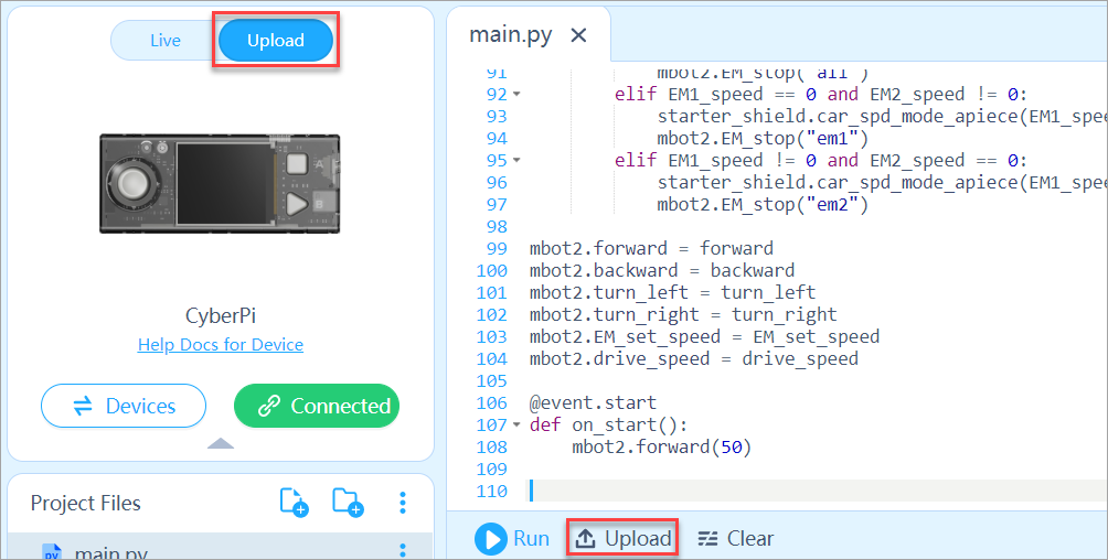
:::info Note: The statement with the key word event can be used only in Upload mode. :::
11. How do I write a program for mBot2 on the Python editor?
For details, see the mBlock-Python Editor Online Help.
12. Do I have to install mLink if I want to use mBlock on the web?
Yes, you have to.
13. What is the LAN function of mBot2, and how to use it?
A local area network (LAN) is a network of connected devices that exist within a specific location. LANs may be found in homes, offices, educational institution, or other areas. A LAN may be wired, wireless, or a combination of the two. -- from https://techterms.com For mBot2, it refers to that multiple CyberPis on the same LAN communicate with each other. Example 1: You can use a CyberPi to control mBot2 based on its main control board (that is, another CyberPi). Example 2: Multiple CyberPis on the same LAN exchange messages with each other or interact with each other to finish a game.
14. How do I set the Wi-Fi connection?
There are three ways to set the Wi-Fi connection.
Way 1
Use the following block in the AI or IoT category to set the Wi-Fi connection.

Way 2
After connecting CyberPi (mBot2) to mBlock5, click Setting, click Set up Wi-Fi, and then enter the Wi-Fi name and password.
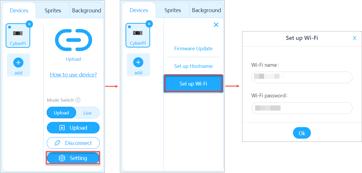
Way 3
Set the Wi-Fi connection on the Makeblock app.
- Open the Makeblock app.
- Choose the device mBot2.
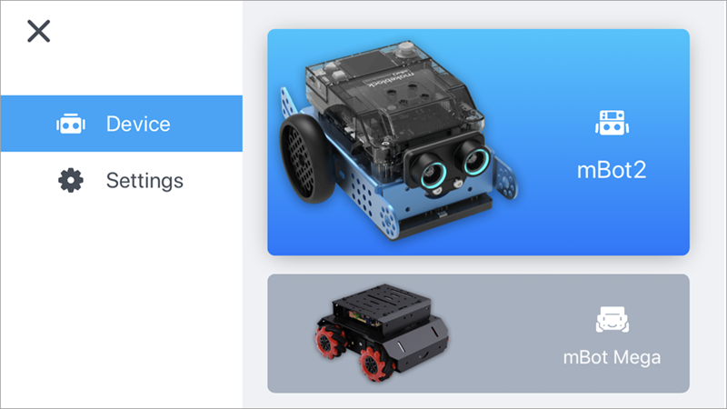
- Click Wi-Fi Guide, click Set Up, and then enter the Wi-Fi name and password.
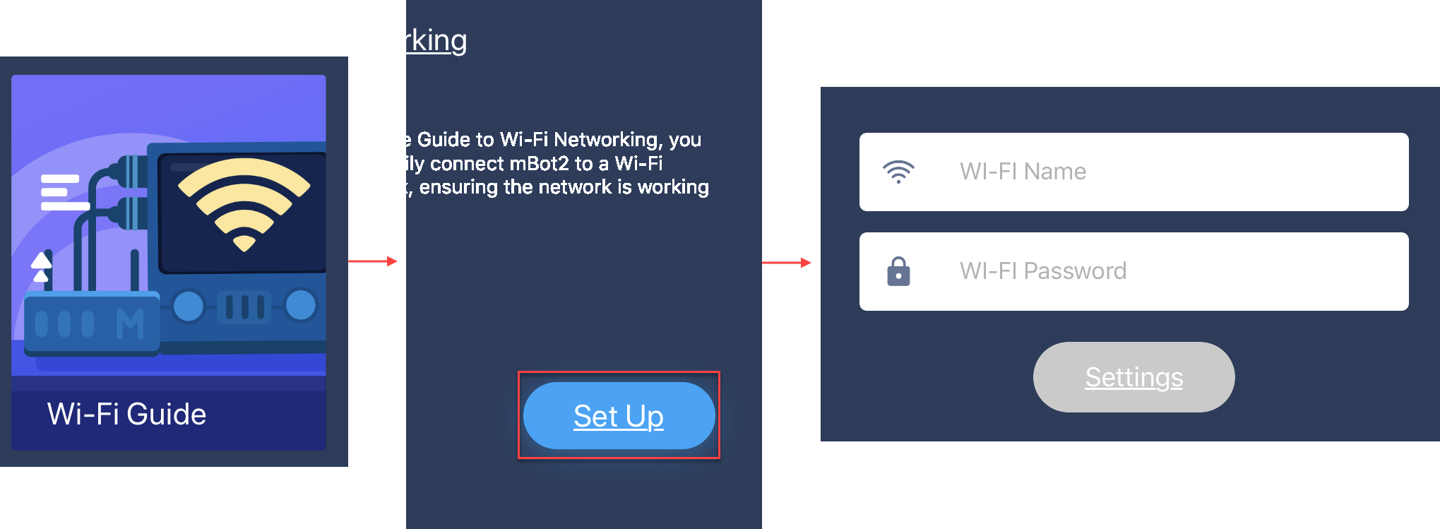
15. How are the line, background, and colors defined for the quad RGB sensor?
The quad RGB sensor provides two functions: line following and color recognition.
- Line following
the quad RGB sensor needs to learn the line and background first. Line and background learning: Place the sensor on the background and double-press the button on the sensor, and then swipe the sensor horizontally over the line and background. For more information about line following, see Quad RGB Sensor.
- Color recognition
The quad RGB sensor can recognize eight colors, namely black, red, green, cyan, blue, yellow, purple, and white.
- Line following & color recognition
The quad RGB sensor can recognize colors while identifying a line and background.
For example, when identifying the black line on a white background, the quad RGB sensor can also recognize the colors on the line.

16. How do I use the quad RGB sensor?
With the quad RGB sensor, mBot2 can recognize colors while following a line.
The following is an example program.
 After you press button A, mBot2 stops moving.
After you press button B, mBot2 starts to follow a line.
After you press in the middle of the joystick, the name of the detected color is diplayed on the screen of CyberPi.
After you press button A, mBot2 stops moving.
After you press button B, mBot2 starts to follow a line.
After you press in the middle of the joystick, the name of the detected color is diplayed on the screen of CyberPi.
FAQs on Troubleshooting
1. The screen of CyberPi isn't lit up or blinks after I power it on by using Pocket Shield or a USB cable. What can I do?
If the screen of CyberPi doesn't work properly after you power it on by using Pocket Shield or a USB cable, you can update the firmware of CyberPi on mBlock 5 as follows:
- Connect CyberPi to mBlock 5. For detailed operation, see "Add and connect CyberPi."
- After connecting CyberPi to mBlock 5, click Setting and then click Firmware Update.
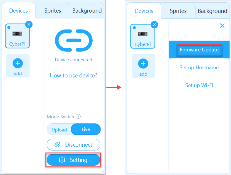
- After updating the firmware, disconnect and then connect the USB cable again, or turn off and then turn on Pocket Shield.
The screen of CyberPi can be lit up properly unless a hardware fault occurs. :::info Note: No power-on indication is provided for CyberPi, and therefore exceptions occur in the firmware may be considered a hardware fault. You can try upldating the firmware first. If the problem remains, a hardware fault may occur. :::
2. After I turn on Pocket Shield or mBot2 Shield, it can't supply power for CyberPi and the blue LED on it keeps blinking. What can I do?
Generally, after you turn on Pocket Shield or mBot2 Shield, the blue LED on it blinks twice or three times and then stays on, as shown in the following.
If the blue LED keeps blinking after you turn on a shield, you can rectify the exception as follows:
- Connect the shield to CyberPi and turn on the shield.
- Connect CyberPi to mBlock 5. For detailed operation, see "Add and connect CyberPi."
- After connecting CyberPi to mBlock 5, click Setting and then click Firmware Update.
- After updating the firmware, disconnect the USB cable and restart the shield.
Unless a hardware fault occus, the blue LED on the shield blinks twice or three times and then stays on.
FAQs on Product Specifications
1. How much load can CyberPi working in combination with Pocket Shield bear?
For common electronic modules instead of motors or servos, no more than 10 modules are recommended; for motors or servos, no more than 4 modules are recommended.
2. FAQs on the LAN communication of CyberPi
What is the working principle of LAN communication?
LAN commnunication between CyberPis is implemented based on the ESP-NOW protocol pf ESP32. Messages can be transmitted through Wi-Fi without Wi-Fi connection. The transmission, however, is not reliable. The data broadcast may fail to be received by the target device due to any one of the possible causes, such as that the LAN has not been started properly and the target device uses another Wi-Fi channel. CyberPis on the same LAN can communicate with each other without Internet access. The communication is implemented in one-to-multiple mode. Generally, one CyberPi can broadcast data to any number of other CyberPis.
My two CyberPis fail to communicate with each other by broadcasting messages on the LAN, why?
CyberPis can't communicate with each other by broadcasting messages on the same LAN if they use different Wi-Fi channels. One CyberPi can't send data to or receive data from another one using a different Wi-Fi channel. Both the LAN broadcasting and Internet access (that is, visiting the Internet through a router) functions of CyberPi are performed based on Wi-Fi and they share one Wi-Fi channel. After you connect CyberPi to a router, the Wi-Fi channel used by CyberPi is the same as that used by the router, which may be different from the default Wi-Fi channel (channel 6) of CyberPi. In the following scenarios, the two CyberPis fail to communicate with each other because they use different Wi-Fi channels:
Scenario 1 CyberPi 1 is connected to router A, and CyberPi 2 is not (due to empty connection setting, incorrect password input, or out of connection range). If the channel used by router A is different from the deafult one (channel 6) of CyberPi, CyberPis 1 and 2 use different Wi-Fi channels and therefore can't communicate with each other.
Scenario 2 CyberPi 1 is connected to router A, and CyberPi 2 is connected to router B. CyberPis 1 and 2 can't communicate with each other if rounters A and B use different Wi-Fi channels.
How do I ensure that two or more CyberPis properly communicate with each other by broadcasting messages on the LAN?
CyberPis can communicate with each other properly by broadcasting messages on the LAN as long as they use the same Wi-Fi channel. You can ensure two or more CyberPis use the same Wi-Fi channel in either of the following ways:
- **Way 1**
Use only the LAN functions of CyberPis. Do not connect any of them to the Internet. In this case, all CyberPis use the default Wi-Fi channel, channel 6. If CyberPi has been connected to the Internet, you can set the Wi-Fi name and password to empty to disconnect it from the Internet. For example, the following program can be used to disconnect CyberPi from the Internet.
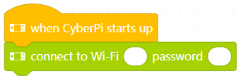
- **Way 2**
Connect all CyberPis to the Internet through the same router. After being connected to a router, CyberPi uses the same Wi-Fi channel as the router, and therefore all CyberPis connected to the same router use the same Wi-Fi channel. Thus, they can communicate with each other while maintaining the access to the Internet.
Other precautions
  - Ensure that the data broadcast on a LAN is no more than 200 bytes. Otherwise, data may be lost.
  - After you connect CyberPi to a router, the Wi-Fi channel it uses depends on the router. If a router uses channel 6, the default Wi-Fi channel of CyberPi, another CyberPi that is not connected to the router can communicate properly with the one connected.
  - After being turned on, CyberPi attempts to connect to the Internet by default. If you have set a Wi-Fi connection for it, it may keep trying to connect to the Internet. Before the connection is complete, the Wi-Fi channel is not determined, and therefore the LAN communication may fail.
3. FAQs on the chassis and encoder motors
Turning errors occur when I control my mBot2, why?
mBot2 is assembled with multiple parts, including metal and plastic structural parts, of which the tolerance can't be completely eliminated due to industrial limitations. Besides, a tolerance is allowed on the assembly of mBot2. All these tolerances may cause turning errors on the chassis of mBot2. This turning error, however, is quite stable and can be rectified by using a turning coefficient.
The following figure shows the program for rectifying the error:
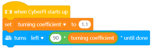 We are now testing a chassis calibration mechanism to rectify the turning error caused by structural tolerances. So far, the turning error can be reduced significantly. You can download the mBot2 motion calibration test and drag it to the PC client of mBlock 5 to use the blocks for reducing the error.
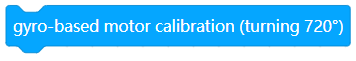
How do I use the blocks for calibrating the chassis of mBot2?
When the gyro-based motor calibration (turning 720°) block is executed, CyberPi lights up its LEDs and turns off the LEDs after mBot2 has turned** **720° and the value output of the gyro is stable. The calibration coefficient obtained is stored on CyberPi and is not deleted after CyberPi is powered off.
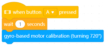
The accumulative error is large after an encoder motor runs multiple times, why?
This is what it is supposed to be. A certain error occurs every time the encoder motor runs, and the error is accumulative after mBot2 runs multiple times. For example, the error is large if the following blocks are executed:
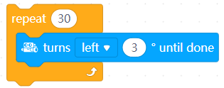
We are making efforts to improve the motion of mBot2, and a new firmware version is expected to be released by the end of July to rectify the accumulative error.
4. FAQs on the quad RGB sensor
How are the line, background, and colors defined for the quad RGB sensor?
The quad RGB sensor provides two functions: line following and color recognition.
- **Line following**
the quad RGB sensor needs to learn the line and background first. Line and background learning: Place the sensor on the background and double-press the button on the sensor, and then swipe the sensor horizontally over the line and background. For more information about line following, see Quad RGB Sensor.
- **Color recognition**
The quad RGB sensor can recognize eight colors, namely black, red, green, cyan, blue, yellow, purple, and white.
- **Line following & color recognition**
The quad RGB sensor can recognize colors while identifying a line and background.
For example, when identifying the black line on a white background, the quad RGB sensor can also recognize the colors on the line.

How do I use the quad RGB sensor?
With the quad RGB sensor, mBot2 can recognize colors while following a line.
The following is an example program.
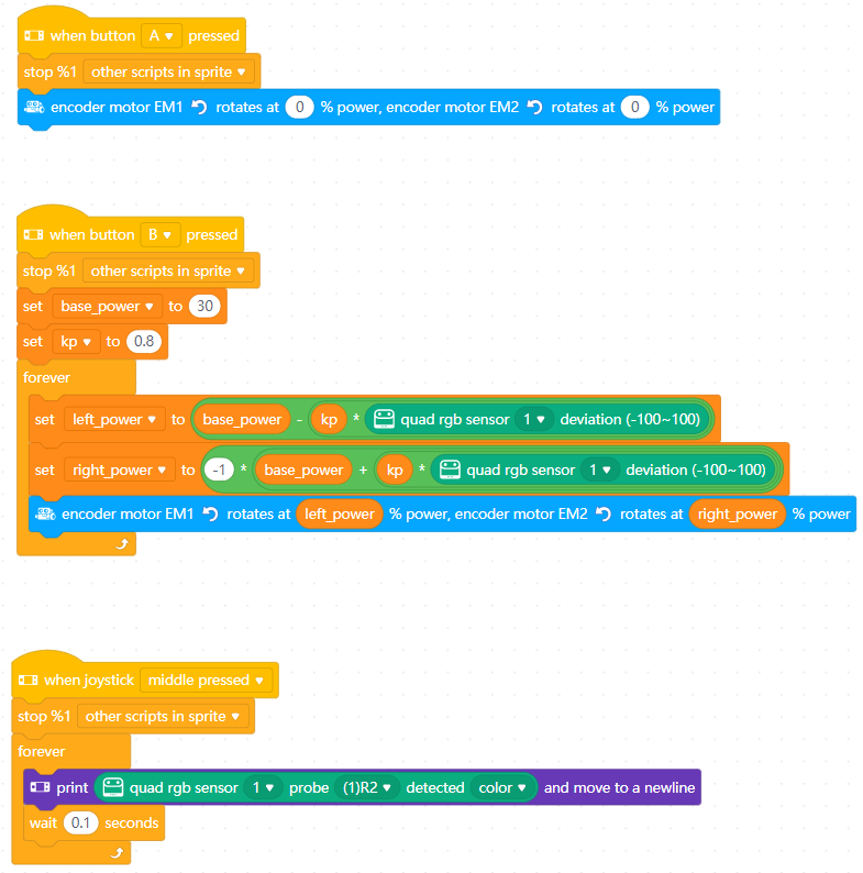 After you press button A, mBot2 stops moving.
After you press button B, mBot2 starts to follow a line.
After you press in the middle of the joystick, the name of the detected color is diplayed on the screen of CyberPi.
After you press button A, mBot2 stops moving.
After you press button B, mBot2 starts to follow a line.
After you press in the middle of the joystick, the name of the detected color is diplayed on the screen of CyberPi.
5. How to change program names on CyberPi?
Change program names only through the web mBlock. Note: There are preset programs and **My Programs on CyberPi, of which the preset programs **can't be renamed or overwritten by an uploaded program. (When you upload a new program while one of the preset programs is being executed, the first program in My Programs is overwritten by the new one. Its name is the default "main" unless it has been renamed.)
For example, steps to change the name of the third program in **My Programs **are as below:
- Choose **My Programs- Program 3 **on CyberPi and press the confirmation key to execute the program.
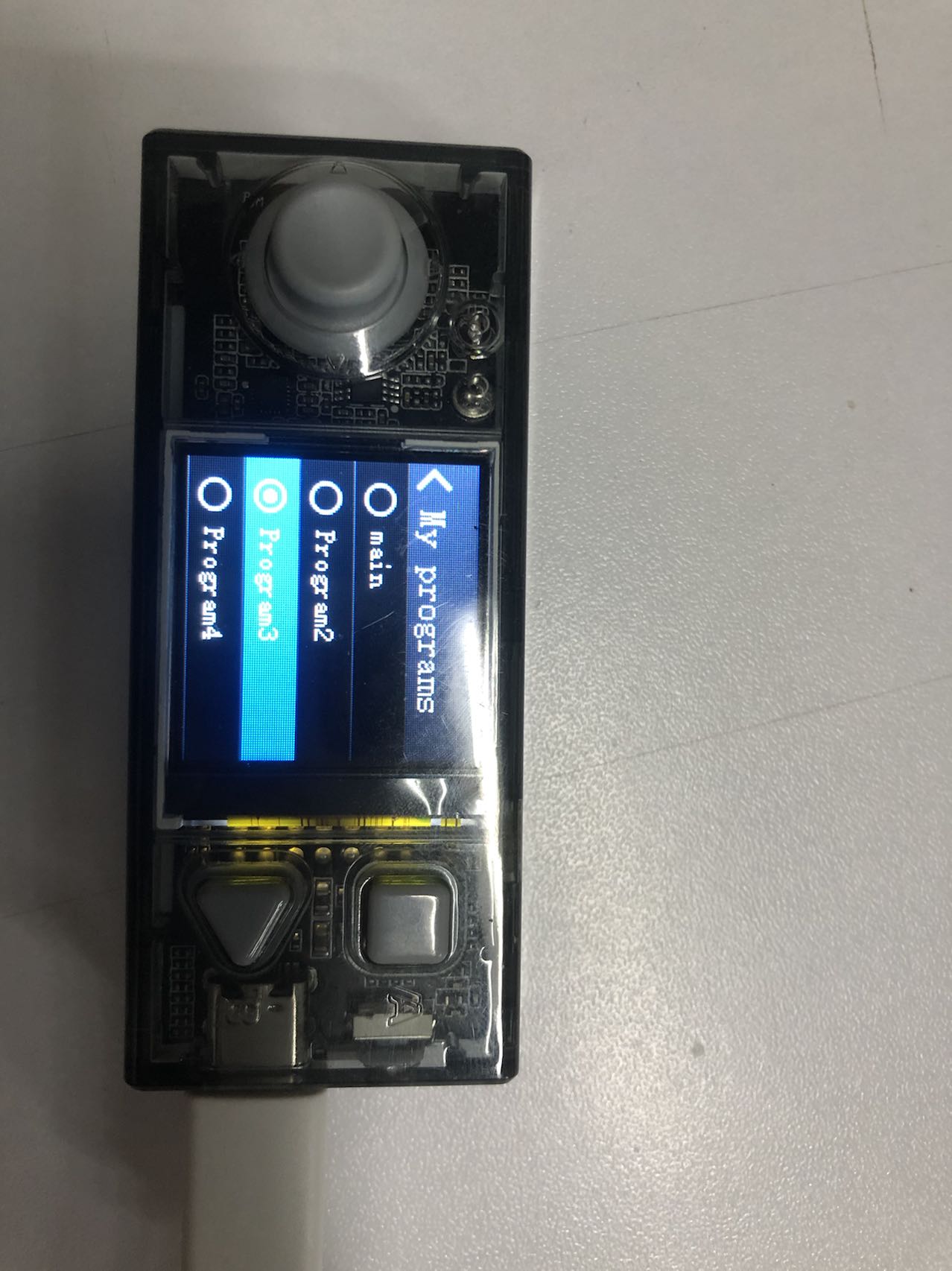
- Connect CyberPi to mBlock in your PC and follow the steps below.
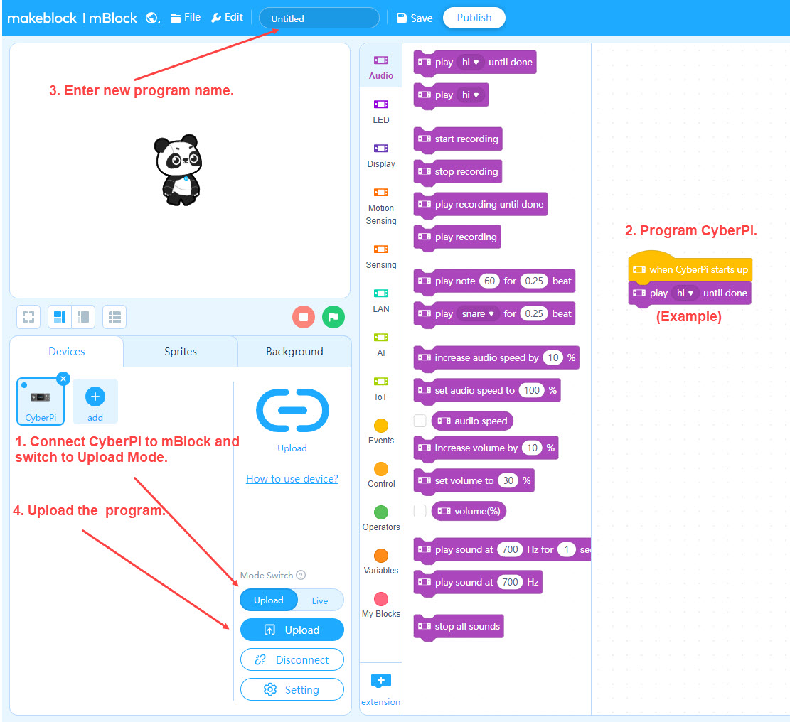
- Restart your CyberPi when the program is uploaded. Open **My Programs **and then you can find the program successfully renamed.
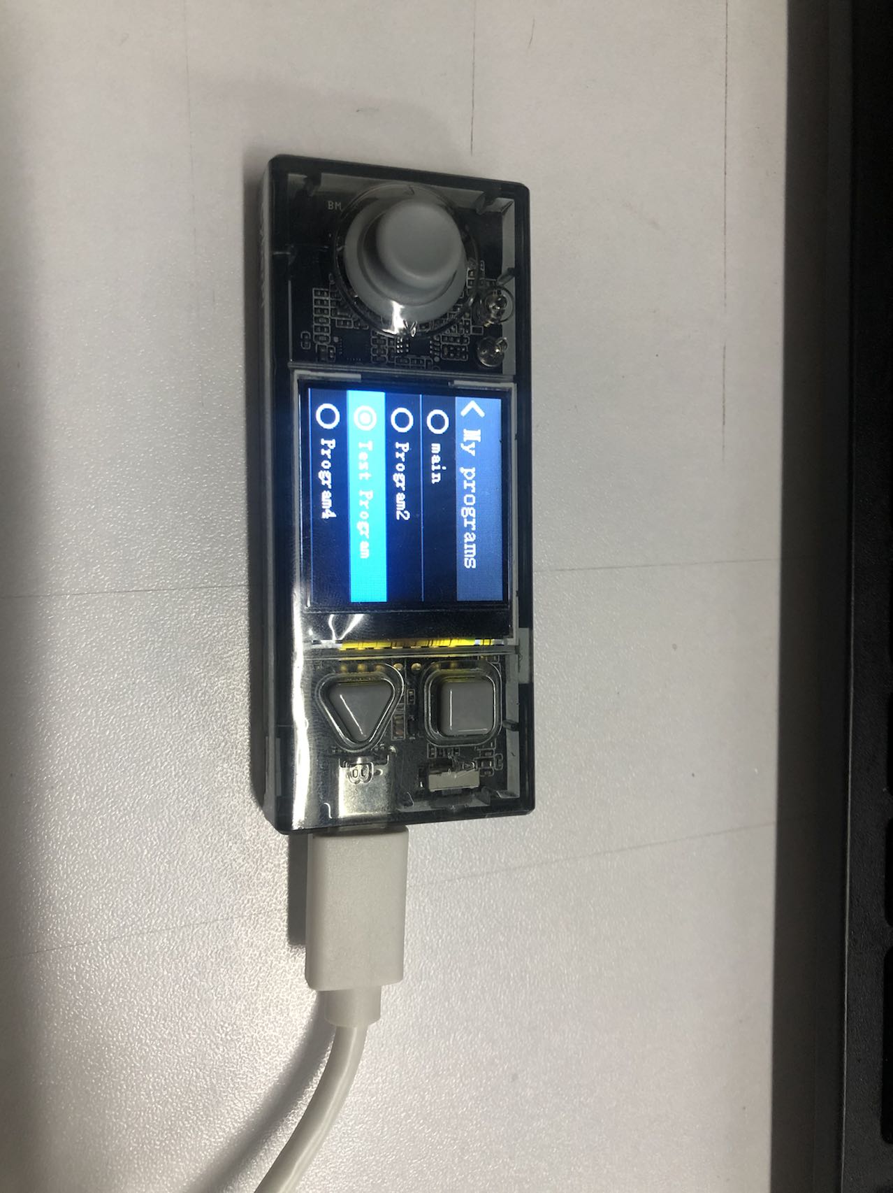
HD photos
You can use them for classroom materials, brochures, etc. Remember to cite the source.
OSHW certification
The OSHW (Open Source Hardware ) certification mark of CyberPi.
CyberPi
mBot2
mBuild modules
Program CyberPi with a Third-party Python Editor
The following is a step by step guide for users with Windows. Mac users may use it as a reference.
Quick start for users who already have a Python environment and a third-party editor installed:
- Skip to step 3, or install pyserial and cyberpi libraries with the following commands:
pip install pyserialpip install cyberpi
1. Set up a Python environment
- Go to the Python.org to select and download Python for your operating system.
- Click the selected version to install, remember to check Add Python 3.6 to PATH, and then click Install Now.
- You can also click Customize installation to install Python environment to a specified directory.
2. Install and configure the third-party Python editor (Visual Studio Code as an example)
Note: The steps may vary depending on the editor you are using. It is also recommended that you configure the installed Python environment in the editor.
- Download VS Code according to your operating system. Download VS Code
- Click the downloaded installation package to install it. (Just follow the prompts to install)
- Click the VS Code icon on the desktop to run the program.
- On the left side of the software interface, find the icon in the red rectangle as shown below and click on it.
- Search for Python extension and install it. Note that the publisher is Microsoft.
- Configure the previously installed Python environment in VS Code editor.
- Create a new folder and a .py file and you can write basic Python programs.
3. Preparation for programming CyberPi with the third party editor
- In Windows OS, press Windows + R on the keyboard, type **CMD **and press Enter, then the CMD window will pop up.
-
Install pyserial library, which ensures that CyberPi is connected to the third-party editor via USB cable or Bluetooth dongle.
Type `pip install pyserial` in the CMD window and press enter, wait for the library to be installed.
-
Install cyberpi library, which is a Python library used for online programming of CyberPi.
 Type ` pip install cyberpi` in the CMD window and press **Enter**, wait until the library is installed.

 You can refer to the [Python API Documentation for CyberPi](https://www.yuque.com/makeblock-help-center-en/mcode/cyberpi-api).
- After the installation is completed, you can write programs in the editor configured with the Python environment.
4. Note
The third-party editor currently only supports online programming for CyberPi.
5. Sample programs
CyberPi mouse
Need to install pynput module. Refer to the above step pip install pynput
""""
Name: Cyber Pi mouse
Introduction:
Use the gyroscope module, buttons of Cyber Pi, and the mouse control function of pynput module, to convert Cyber Pi into a mouse.
You can also use the Bluetooth module to convert Cyber Pi into a wireless mouse.

""""
from pynput.mouse import Button, Controller
import cyberpi
import time

mouse = Controller()

while True:
    if cyberpi.is_tiltback():
        mouse.move(-3, 0)
        print(mouse.position)
    if cyberpi.is_tiltforward():
        mouse.move(3, 0)
    if cyberpi.is_tiltleft():
        mouse.move(0, -3)
    if cyberpi.is_tiltright():
        mouse.move(0, 3)
    if cyberpi.controller.is_press("b"):
        mouse.press(Button.left)
        mouse.release(Button.left)
        mouse.press(Button.left)
        mouse.release(Button.left)
    if cyberpi.controller.is_press("a"):
        mouse.press(Button.right)
        mouse.release(Button.right)
    time.sleep(0.01)
CyberPi voice typer
""""
Name: 074 Cyber Pi voice typer
Hardware: Cyber Pi
Introduction:
Use the voice recognition function of Cyber Pi, and the keyboard control function of pynput module.
The result of voice recognition will be printed out in a file through pynput.
This program currently only supports English.

""""
import cyberpi
from pynput.keyboard import Key, Controller
import time

keyboard = Controller()
cyberpi.console.clear()
cyberpi.led.on(0, 0, 0)
cyberpi.set_recognition_url()
cyberpi.cloud.setkey("Enter the cloud service authorization code")    # You can get it through your mBlock account
cyberpi.wifi.connect("WIFI name", "WIFI password")
while not cyberpi.wifi.is_connect():
    pass
cyberpi.led.on(0,0,255)
cyberpi.console.println("WIFI connected")
cyberpi.console.println("--------------")
cyberpi.console.println("Press the button A to start voice recognition")
while True:
    if cyberpi.controller.is_press('a'):
        keyboard.press(Key.space)
        cyberpi.console.clear()
        cyberpi.led.on(100, 0, 0)
        cyberpi.console.println("Start voice recognition")
        cyberpi.audio.play("switch")
        cyberpi.console.println("--------------")
        cyberpi.cloud.listen("english", 2)
        cyberpi.led.on(0, 0, 0)
        say = cyberpi.cloud.listen_result()
        cyberpi.console.println(say)
        cyberpi.console.println("--------------")
        for i in say:
            if i == '':
                 keyboard.press(' ')
            else:
                keyboard.press(str(i))
                time.sleep(0.03)
Matplotlib volume histogram
import cyberpi
import time
from matplotlib import pyplot as plt

plt.rcParams['font.sans-serif'] = ['Microsoft YaHei']
plt.ion()

while True:
    loud = cyberpi.get_loudness()
    plt.clf()
    plt.xlabel("Data name")
    plt.ylabel("Volume readings")
    y_locator = plt.MultipleLocator(5)
    ax=plt.gca()
    ax.yaxis.set_major_locator(y_locator)
    plt.ylim(0,100)
    plt.bar('Volume', loud, align='center',label=f'Temperature{loud}')
    plt.title('Cyber Pi sound sensor readings')
    plt.legend()
    plt.show()
    plt.pause(0.01)
Matplotlib multi-chart display
from matplotlib import pyplot as plt
import time
import cyberpi

loud_list = []
bri_list = []
plt.rcParams['font.sans-serif'] = ['Microsoft YaHei']
plt.ion()
plt.figure(figsize=(10,10))
plt.figure(1)
x_locator = plt.MultipleLocator(5)
y_locator = plt.MultipleLocator(5)
while True:
    loud = cyberpi.get_loudness()
    bri = cyberpi.get_bri()
    loud_list.append(loud)
    bri_list.append(bri)
    battery = cyberpi.get_battery()
    size = [battery, 100-battery]
    status = [f'Remaining power:{battery}%', f'Power used:{100-battery}%']
    ax1 = plt.subplot(221)
    plt.title('Light line chart')
    ax1.plot(bri_list)
    ax2 = plt.subplot(222)
    plt.title('Sound histogram')
    ax2.xaxis.set_major_locator(x_locator)
    ax2.yaxis.set_major_locator(y_locator)
    plt.ylim(0,100)
    ax2.bar('sound', loud)
    ax3 = plt.subplot(223)
    ax3.xaxis.set_major_locator(x_locator)
    ax3.yaxis.set_major_locator(y_locator)
    plt.xlim(0,100)
    plt.ylim(0,100)
    plt.title('Sound and volume scatter chart')
    ax3.scatter(loud_list,bri_list)
    ax4 = plt.subplot(224)
    ax4.pie(size, labels = status, radius=1,wedgeprops = {'width': 0.3, 'edgecolor': 'w'})
    plt.title('Cyber Pi power')
    plt.pause(0.2)
    plt.clf()
    if cyberpi.controller.is_press('a'):
        break
    if len(bri_list) > 500:
        bri_list = []
        loud_list = []
Iteration 007
Foreword
This page provides details about iteration 007 of CyberPi.
Most iterations upgrade the product incrementally while being compatible with earlier versions, so the programs you compile for earlier versions can be used in the latest version.
Understanding the information on this page may require some background knowledge. If you have already purchased the latest version of CyberPi, or are using an earlier version and have no questions about feature updates, you don't have to read this page.
Version description —— compared with version 006
- Added the underlying feature of Wi-Fi-based field control for subsequent official release of functions
- Optimzied the start and menu UIs of CyberOS, facilitating the use of preset programs
- Fixed the found bugs and supported the enhanced version of mBot2 Shield, in which an external battery port was provided
- Fixed some bugs of the Network APIs to faciliate the further development of courses using CyberPi in fields such as communication engineering
- Added APIs for mBot2 in the Python 3 library developed for CyberPi
- Added blocks and functions to the 8×16 LED matrix and quad RGB sensor | Release date | September 30 | | --- | --- | | Hardware version | CyberPi PCB V1.1 Pocket Shield PCB V1.1 mBot2 Shield PCB V1.1 (PCBA V1.0) mBot2 Shield PCB V1.2 *An external battery port is added to mBot2 Shield V1.2, so that mBot2 can be used in competitions with higher performance requirements. | | Firmware version | CyberPi 007 firmware (NEW) Pocket Shield 006 firmware mBot2 Shield 004 firmware (NEW) | | mBlock extension | Cyberpi 1.1.20(NEW) pocket_shield 0.03 mbot2 0.02 mbuild_quad_color_sensor 0.02 cyberpi_mbuild_ultrasonic2 0.01 cyberpi_mbuild_science 0.01 halocode_network 0.0.2(NEW) | | mBlock IDE | Web version 1.0.4 PC version 5.3.1 Mobile version 2.1.3 |
New features
Wi-Fi-based field control
In 433 band-based field control mode, MakeboX communicates with the power management module on the robot through the 433 band and thus controls the robot and obtains its status information. In the Wi-Fi-based field control mode, MakeboX interacts with the robot based on the Wi-Fi ESP32_NOW protocol. In all the coming competition events where CyberPi is used, MakeboX will control robots and obtain their status information in the Wi-Fi-based field control mode.
CyberOS UIs
The following UI is added on CyberOS. Choose Settings > About CyberPi to find it. After you scan the QR code with your smart phone where the MakeX officiating app is installed, your smart phone, MakeboX, and CyberPi can communicate with each other wirelessly.
With the Wi-Fi-based field control technology and MakeboX, the MakeX officiating app can pause, restart, and monitor the status of robots in competitions, which can be expected in the some of 2022 competitions.
New block and MicroPython API
| Block (available only in Upload mode) | API |
|---|---|
| |
| You can find this block in the Sensing category after adding CyberPi from the device library. | cyberpi.is_makex_mode(name) |
| Determines what stage CyberPi is in. Parameters: |
namestr, indicating the possible state of a competition. Value range:auto:automatic modemanual:manual mode
Returns a boolean value. Note: A competition can be in another state instead of these two states, subject to the default states you have defined on CyberPi before connecting it to MakeboX. |
Official release of the Bluetooth Controller extension for CyberPi
The 007 firmware officially supports the Bluetooth Controller extension, and you can use the following blocks to write your programs.
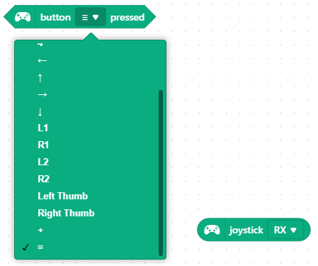
Chassis calibration
The chassis calibration function is added. With this function, after you change the wheelbase and wheel diameter of mBot2, it still can execute commands, such as turning 90 degrees, accurately through calibration and intelligent turning coefficient setting. In addition, this function, to some extent, resolves the problem of inaccurate turning caused due to improper building of mBot2.
| Block (available only in Upload mode) | APIs |
|---|---|
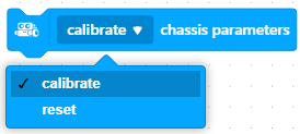 | mbot2.set_auto() |
| mbot2.reset() |
Showing expression with the 8×16 LED matrix
An expression block is added in the 8×16 LED Maxtrix extension for CyberPi. You can use this block to write programs for mBot2, making it a robot with emotions.
| Block (available only in Upload mode) | APIs |
|---|---|
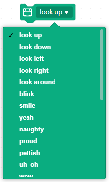 | cyberpi.emotion.look_up() |
| cyberpi.emotion.look_down() | |
| cyberpi.emotion.look_left() | |
| cyberpi.emotion.look_right() | |
| cyberpi.emotion.look_around() | |
| cyberpi.emotion.blink() | |
| cyberpi.emotion.smile() | |
| cyberpi.emotion.yeah() | |
| cyberpi.emotion.naughty() | |
| cyberpi.emotion.proud() | |
| cyberpi.emotion.yummy() | |
| cyberpi.emotion.uh_oh() | |
| cyberpi.emotion.wow() | |
| cyberpi.emotion.hurt() | |
| cyberpi.emotion.sad() | |
| cyberpi.emotion.angry() | |
| cyberpi.emotion.hello() | |
| cyberpi.emotion.sprint() | |
| cyberpi.emotion.startle() | |
| cyberpi.emotion.shiver() | |
| cyberpi.emotion.dizzy() | |
| cyberpi.emotion.sleepy() | |
| cyberpi.emotion.zzz() | |
| cyberpi.emotion.wake_up() | |
| cyberpi.emotion.yes() | |
| cyberpi.emotion.no() |
Official release of the Network extension
In version 007, bugs reported by users are fixed and the Network extension is officially released. You can use it to teach network communications. Your feedback and suggestions are welcome, and we will improve the extension accordingly to give full play to the value of CyberPi in education.
| Blocks (available in both Upload and Live modes) | Function | API(s) |
|---|---|---|
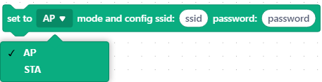 | cyberpi.network.config_ap(ssid, password) | |
| cyberpi.network.config_sta(ssid, password) | ||
 | Determines whether CyberPi connects to the network | cyberpi.network.is_connect() |
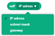 | cyberpi.network.get_ip() | |
| cyberpi.network.get_subnet_mark() | ||
| cyberpi.network.get_gateway() | ||
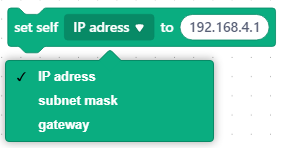 | str | |
| Example: '192.168.4.1' | cyberpi.network.set_ip(ip) | |
 | cyberpi.network.create_client() | |
 | ip : '192.168.4.1' | |
| port: 5050 | cyberpi.network.client_connect_to(ip, port) | |
 | cyberpi.network.create_server(port) | |
 | cyberpi.network.server_wait_connection(port) | |
 | cyberpi.network.server_get_latest_connection(port) | |
 | cyberpi.network.server_get_connections(port) | |
 | cyberpi.network.server_get_connections(port)[index] | |
 | Messages sent using this API will end with a line break. | |
| data:str | ||
| ip_to:str | ||
| port:int | cyberpi.network.write_line(data, ip_to, port) | |
 | When this API is run, CyberPi listens for messages from 192.168.4.1 at the port it specifies. When a line break is received, CyberPi determines that a full line of data is received and returns the received message. |
ip_from: str
port: int | cyberpi.network.read_line(ip_from, port) |
|  | data: str
ip_to: str
port: int | cyberpi.network.write(data, ip_to, port) |
|
| data: str
ip_to: str
port: int | cyberpi.network.write(data, ip_to, port) |
|  | When this API is run, CyberPi listens for messages from 192.168.4.1 at the port it specifies until the data received reaches the specified length, and CyberPi will return a message at the specified length.
ip_from: str
data_size: int
port: int | cyberpi.network.read(ip_from, data_size, port) |
| When this API is run, CyberPi listens for messages from 192.168.4.1 at the port it specifies until the data received reaches the specified length, and CyberPi will return a message at the specified length.
ip_from: str
data_size: int
port: int | cyberpi.network.read(ip_from, data_size, port) |
In Simple Network mode, CyberPi works as a client (STA) by default and connects to other non-CyberPi devices (e.g. a phone, a server on a LAN). By default, port 5050 is used to implement data communication.
| Blocks (available in both Upload and Live modes) | Function | API(s) |
|---|---|---|
 | Establish a connection between CyberPi and the AP with the corresponding ssid, password, and ip address. Set CyberPi as a client. | cyberpi.network.config_sta(ssid, password) |
| cyberpi.network.create_client() | ||
| cyberpi.network.client_connect_to(ip, port=5050) | ||
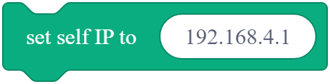 | Change your IP address | cyberpi.network.set_ip(ip) |
 | Connect to a "server" at a specific address and send a message | cyberpi.network.client_connect_to(ip, port=5050) |
| cyberpi.network.write_line(data, ip_to, port) | ||
 | Read data from a specific server | cyberpi.network.read_line(ip_from, port=5050) |
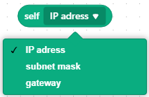 | cyberpi.network.get_ip() | |
| cyberpi.network.get_subnet_mark() | ||
| cyberpi.network.get_gateway() | ||
 | cyberpi.network.is_connect() |
Providing the user cloud message function in Python 3 programming [coming soon]
We will soon update the Python 3 library for Cyberpi to support the user cloud message function. Stay tuned to the updates in the Python API Documentation for CyberPi.
BUG fixes and user experience improvement
Added Python 3 Programming for mBot2 [coming soon]
Most of the features supported by MicroPython will be supported by Python 3. For example, mBot2 will support Python 3 programming. Stay tuned to the updates in the Python API Documentation for CyberPi.
Modified the Wi-Fi function
In versions earlier than 007, CyberPi automatically connects to the Wi-Fi network it has connected to last time, which affects the ESP32-NOW communication. Therefore, this function is deleted, and you need to connect CyberPi to the Wi-Fi network through the block or API.
| Blocks (available in both Upload and Live modes) | Function | API |
|---|---|---|
 | CyberPi stores the name and password of the last Wi-Fi network it has connected to and connects to that network when this block is used. | cyberpi.Wi-Fi.reconnect() |
 | Disconnects CyberPi from the Wi-Fi network. | |
| CyberPi is restored to the default communication channel to ensure the LAN broadcast quality of the CyberPi. | cyberpi.Wi-Fi.disconnect() |
Modified the fast charging function for mBot2
To improve the fast charging experience on mBot2, the fast charging activation function is deleted. You don't need to activate fast charging any more. In version 007, by default, fast charging is enabled when the power switch of mBot2 is turned off.
Optimized CyberOS
Updated the start UI
The start UI is updated due to the new VI of Makeblock.
Modified the menu hierarchy and items
- Programs are categorized into** Preset** and **My programs **after you choose Switch Program.
- The items About CyberPi and Reset CyberPi are added after you choose Settings.
- The option Activate fast charging is deleted.
Revised texts
Known text mistakes are corrected.
Increased the function of the HOME button
After pressing **HOME **to enter CyberOS, you can press **HOME **again to quickly return to the homepage.
Added the function for displaying the battery level of an external battery
After connecting the enhanced mBot2 Shield to CyberPi, the external battery level is also displayed. You can clearly see the status of both the internal and external batteries.
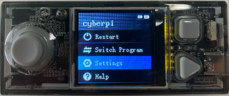 (The battery icon on the right indicates the power level of the internal battery, and that on the left indicates the power level of the external battery.)
Block and MicroPython APIs
| **Block (supports both the upload and live modes) ** | API |
|---|---|
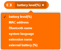 | cyberpi.get_extra_battery() |
| Returns the power level of the external battery, 0–100 | |
| This function is available only for mBot2 Shield V1.2. |
Added the function for displaying the firmware version of an extension board
Choose Settings > Update. The firmware version of the extension board is shown, so that you can understand the firmware versions of your devices.
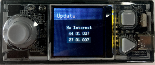
Added the function for resetting CyberPi
Choose **Settings **> Reset. When the reset starts, the following UI is displayed:
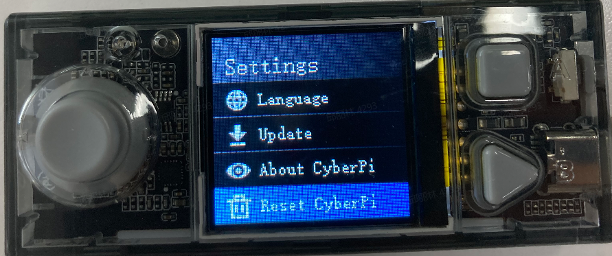 When the reset is complete, the homepage is displayed.
Resetting CyberPi deletes all the data you've uploaded to CyberPi, all the Wi-Fi settings, and the name you set for CyberPi.
When the reset is complete, the homepage is displayed.
Resetting CyberPi deletes all the data you've uploaded to CyberPi, all the Wi-Fi settings, and the name you set for CyberPi.
Added the items Preset and My programs
After you choose Switch program, you can choose between Preset and My programs.
Program SNs are deleted to give space for program names.
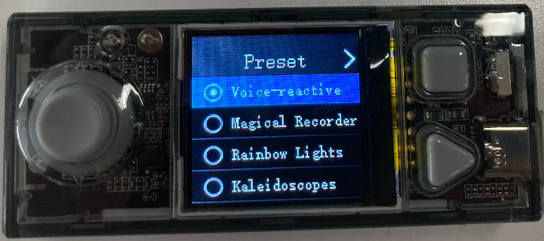
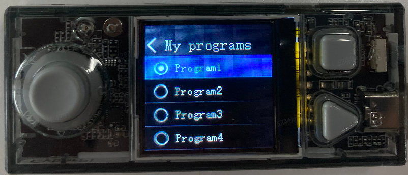 (You can pull the joystick to left or right to switch between preset programs and user-defined programs.)
Preset programs
The Preset programs include several default programs. Names are given to help users understand the functions of the programs.
My programs
My programs are programs uploaded by users. Names you set for the programs on mBlock 5 are displayed.
Logic of overriding in program uploading
When a preset program is being executed, a program you upload replaces Program1 in My programs.
Improved the motion performance of mBot2
- Used the chassis calibration function to reduce errors that may occur when mBot2 moves forward or makes turnings.
- Updated the CyberPi firmware to control the accumulative errors of the encoder motors rotating in angles within ±3° in a single thread.
- Deleted the default self-locking setting for the encoder motors in the CyberPi firmware, so that no unexpected sounds are made by the encoder motors when they are not moving (when their speed are set to 0).
Improved the Quad RGB Sensor extension
The user-defined color option is added.
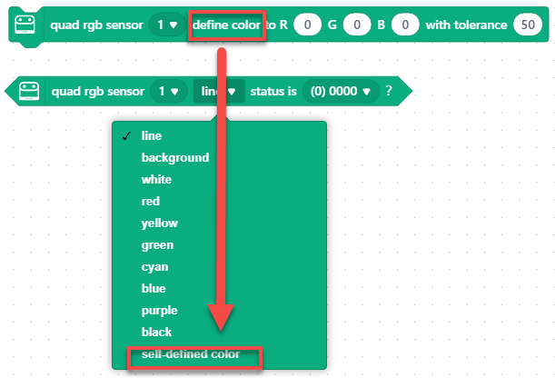
Blocks and micro-python API
| Blocks (available in both Upload and Live modes) | APIs | Function |
|---|---|---|
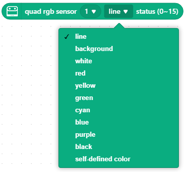 | mbuild.quad_rgb_sensor.get_line_sta(position, index) | |
| mbuild.quad_rgb_sensor.get_ground_sta(position, index) | ||
| mbuild.quad_rgb_sensor.get_white_sta(position, index) | ||
| mbuild.quad_rgb_sensor.get_red_sta(position, index) | ||
| mbuild.quad_rgb_sensor.get_yellow_sta(position, index) | ||
| mbuild.quad_rgb_sensor.get_green_sta(position, index) | ||
| mbuild.quad_rgb_sensor.get_cyan_sta(position, index) | ||
| mbuild.quad_rgb_sensor.get_blue_sta(position, index) | ||
| mbuild.quad_rgb_sensor.get_purple_sta(position, index) | ||
| mbuild.quad_rgb_sensor.get_black_sta(position, index) | ||
| mbuild.quad_rgb_sensor.get_custom_sta(position, index) | ||
| Position: "middle" or "all" | ||
| middle:L1, R1 | ||
| all: L2, L1, R1,R2 | The quad RGB sensor identifies the status of the color, line, and background. | |
| Returning 1 means the identification result of the corresponding probe is true. | ||
| 0 means the probe does not identify the corresponding color, line or background. | ||
| The final return value is the decimal value corresponding to the binary value of 0000~1111, and the type is int. | ||
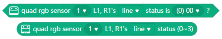 | ||
 | You can get the transcode of these blocks based on the preceding APIs. | |
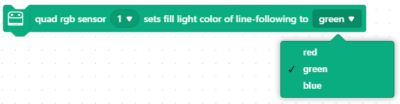 | mbuild.quad_rgb_sensor.set_led_color() | Set the color of the fill light in line following. Using this function will overwrite the fill light color setting selected for line-following learning. |
 | mbuild.quad_rgb_sensor.close_led() | Temporarily turn off the fill light. When any sensing function of the line-following sensor is used, the line-following fill light is lit up. |
Iteration 006
Foreword
This page describes the details about iteration 006 of CyberPi. The outcome of each iteration is a major version of CyberPi.
Most of the iterations will upgrade the product incrementally while being compatible with the earlier versions, and therefore, your programs compiled for the earlier versions can be used in the latest version.
Understanding the information provided on this page may require some background information. If you have purchased the latest version of CyberPi or use an earlier version without questions about the function updates, you don't have to read this page.
Version description
Compared to version 005, version 006 provides some new functions and features and resolves the found bugs. In this version, APIs related to our new sensor Science Sensor are supported, and the APIs and functions of the Display+ extension are tested and improved.
| Launch date | March 31, 2021 |
|---|---|
| Hardware version | CyberPi PCB V1.1 |
| Pocket Shield PCB V1.1 | |
| mBot2 Shield PCB V1.1 (PCBA V1.0) | |
| Firmware version | CyberPi 006 (NEW) |
| Pocket Shield 006 | |
| mBot2 Shield | |
| Block plugin version | cyberpi 1.0.12 (NEW) |
| pocket_shield 0.03 | |
| mbot2 0.02 (NEW) | |
| mbuild_quad_color_sensor 0.02 (NEW) | |
| cyberpi_mbuild_ultrasonic2 0.01 (NEW) | |
| cyberpi_mbuild_science 0.01 (NEW) | |
| mBlock 5 version | Web version 1.0.4 |
| PC client version 5.3.1 | |
| Mobile app version 2.1.3 |
Firmware update
Way 1: Open mBlock 5 and update the firmware of CyberPi as prompted. If mBlock 5 doesn't prompt you to update the firmware, your CyberPi runs with the latest firmware. Way 2: Connect your CyberPi to the Internet through Wi-Fi, enter CyberOS, and choose Settings > Update. The system checks the current version and updates the firmware if it is not the latest version.
Way 2 is recommended. It takes less time to complete firmware update.
New features
Error report
When an error occurs during program execution, CyberPi reports the error on its screen.
User-defined program name
After you upload a program to CyberPi, the name you've set for the program is displayed in the program list when you switch programs on CyberOS.
For example, I write a program, name it makeblock, and upload it to CyberPi. Then, I can see the program makeblock when I switch programs.
:::info
**Note: **The program uploaded is the third program because the last program I executed before uploading this prorgam was the third one.
:::
mBlock 5 mobile apps (for iOS and Android)
The mobile apps of mBlock 5 support CyberPi and its extensions. You can download the apps in app stores. Make sure that the app version is v2.1.3 or later.
Use your phone or tablet to scan the QR code to download the app.
Alternatively, search for "Makeblock" in app stores to download the app.
Science sensor
The science sensor is a new mBuild module. You can add the Science Sensor extension on mBlock 5 to program the science sensor.
Official release of the Display+extension
The Display+ extension and its related functions are tested, improved, and stabilized.
Bluetooth Controller
CyberPi supports Bluetooth Controller. After connecting Bluetooth Controller to CyberPi through Bluetooth, you can add the Bluetooth controller extension on mBlock 5 to program it to control CyberPi or mBot2.
Preset emotions provided for Ultrasonic Sensor 2
Several preset emotions are provided for Ultrasonic Sensor 2, facilitating the expression of your emotions.
After adding the Ultrasonic Sensor 2 extension, you can use the emotion block.
Fast charging for mBot2 Shield
The fast charging function is available only for mBot2 Shield.
On CyberOS, choose Settings > Fast charging to start charging mBot2 Shield. The charging voltage and current is 5 V and 2 A.
:::info
Note: Extension boards can be charged through CyberPi only at the voltage of 5 V. Do not use a power adapter whose output voltage exceeds 5 V to charge them.
:::
New features for closed testing
Google Sheets (outside China Mainland)
CyberPi can use public Google sheets through the Google Sheets extension. With this function, you can upload data output by sensors and collect statistics on the data in the sheets.**
Permissions to control Wi-Fi, Bluetooth, and pins
APIs for controlling the Wi-Fi, Bluetooth, and pins are provided at the micro-python API layer.
User experience improvement
On mBlock 5, choose Tutorials > Example Programs and click mBot2 to view example programs provided for mBot 2.
Iteration 003
Foreword
This page describes the details about iteration 003 of CyberPi. The outcome of each iteration is a major version of CyberPi.
Most of the iterations will upgrade the product incrementally while being compatible with the earlier versions, and therefore, your programs compiled for the earlier versions can be used in the latest version.
Understanding the information provided on this page may require some background information. If you have purchased the latest version of CyberPi or use an earlier version without questions about the function updates, you don't have to read this page.
Version description
The outcome of iteration 003 is the first major version of CyberPi. The following table describes the versions of its hardware, firmware, and block plugin.
| Launch date | August 20, 2020 |
|---|---|
| Hardware version | CyberPi PCB V1.1 |
| Pocket Shield PCB V1.1 | |
| Firmware version | CyberPi 003 (NEW) |
| Pocket Shield 006 (NEW) | |
| Block plugin version | cyberpi 1.0.9 (NEW) |
| sprite 0.01 (NEW) | |
| pocket 0.03 (NEW) |
Firmware update
Open mBlock 5 and update the firmware of CyberPi as prompted. If mBlock 5 doesn't prompt you to update the firmware, your CyberPi runs with the latest firmware. Alternatively, connect your CyberPi to the Internet through Wi-Fi, enter CyberOS, and choose Settings > Update. The system checks the current version and updates the firmware if it is not the latest version.
Iteration summary
1. Rectification and improvement
Rectified the problems found in firmware version 002 to stabilize the blocks and functions of CyberPi, and made some improvement, as described in the following:
- Removed the tight coupling between the brush color and text settings. In the earlier version, the printing of texts changed immediately with the change of the brush color; in this version, after setting the brush color, it is applied to a text only after you program to print the text again.
- Modified the playing of sounds in Live mode to be consistent with that in Upload mode, enabling the playing in Live mode to be interrupted by another thread.
- Fine-tuned the mechanism of beats for the piano playing blocks, making the implementation logic consistent with that of the Music extension for sprites on mBlock 5.
- Optimized the playing mechanism of the buzzer, eliminating the playing interruption caused by frequency change.
- Rectified the errors that occurred when a bar chart was rotated on the screen.
- Rectified the problems that bar charts and line charts supported only integers.
- Improved the display of line charts, stopping it from starting at the zero-point.
- Improved the format of tables, replacing the graduated-color style with the black-and-white style
- Modified the execution logic the event headers in Live mode to be consistent with that in Upload mode on mBlock 5, that is, one event header corresponds to only one thread instead of multiple ones when it is triggered multiple times
- Updated the default programs provided on CyberPi. The original programs included some politically sensitive elements and might cause copyright issues. In this version, blocks and Python code of all the default programs can be provided to users.
- Rectified the problem that CyberPi failed to automatically connect to the Internet through the configured Wi-Fi name and password. In this version, after you set the Wi-Fi name and password for your CyberPi on mBlock 5, CyberPi attempts to connect to the Internet every time it is started.
- Rectified the problem that CyberPi prompted you to update the firmware even when it ran with the latest firmware.
- Modified the execution logic of the block restart CyberPi in Live mode to be consistent with that in Upload mode. In this version, after the block restart CyberPi is executed in Live mode, all the blocks under the block when CyberPi starts up are executed again.
2. New features
Added some new features to enhance the functions of CyberPi, as described in the following:
- Setting the color of texts in a table by setting the brush color
- Displaying texts in multiple fonts in any positions
- Displaying to-be-printed texts in multiple fonts
- Prompting you to set the system language when CyberPi is started for the first time
- Providing more system languages, including Simplified Chinese (简体中文), English, Traditional Chinese (繁體中文), Japanese (日本語), Korean (한국어), Spanish (Español), Italian (taliano), French (Français), and German (Deutsch)
- Providing the interface for obtaining the system language
- Recognizing speeches of common countries and regions
- Translating texts into more languages
- Providing a new charging mechanism, enabling faster charging. In this version, when Pocket Shield and CyberPi are connected to a PC or charger and you turn Pocket Shield off, CyberPi enters the charging mode, displaying the charging state in real time.
- Providing the block for numeric type conversion in the Operators category
3. Unstable features
We have also provided some features that are not fully stabilized for teachers and students to create some basic design. Efforts will be made to ensure the compatibility of later official versions with projects created in the earlier versions.
- Providing the Sprites extension and APIs (supporting only the Upload mode), enabling you to create and run apps and games on CyberPi
- Providing the Doodle extension and APIs (supporting only the Upload mode), enabling you to draw sketches similar to Python Turtle drawings on CyberPi. In addition, the sketches you draw can be set as sprites and thus used in apps or games you create.
- Cancelling the Bluetooth connection function. Currently, mBlock 5 on the web and mBlock 5 PC client don't support Bluetooth connection of CyberPi due to the implementation mechanism of mLink 2. We may enable this function in the future. To enable the wireless connection between CyberPi and mBlock 5, you can purchase Makeblock Bluetooth Dongle or use mBlock 5 mobile app.
CyberPi Warranty Assurance
Environmental Protection and Certification Reports
For better education and a better tomorrow
Makeblock not only designs products for better education, but is also concerned with environmental responsibility. Makeblock is committed to using safe, compliant materials in production to ensure product safety and is working on increasing the percentage of renewable materials to reduce adverse impact on the Earth's environment. You can find the environmental protection and certification reports of the main products of Makeblock in the following:
CyberPi
CyberPi
CE certificate-AT18220WC000856 MCP-K01-01 CE-RED.pdf FCC AT18220WC000857 MCP-K01-01 FCC ID.pdf RoHS AT18300RC002519-Cyberpi--RoHS nbsp.pdf
Pocket Shield
CE AT18230EC001528 MCP-P01-02 CE.pdf FCC Anbotek FCC SDoC of Compliance(18230EC001529 FCC-SDoC).pdf.pdf%22%2C%22size%22%3A124621%2C%22type%22%3A%22application%2Fpdf%22%2C%22ext%22%3A%22pdf%22%2C%22source%22%3A%22%22%2C%22status%22%3A%22done%22%2C%22mode%22%3A%22title%22%2C%22download%22%3Atrue%2C%22taskId%22%3A%22u24eb4aed-3803-4ed7-82fc-c5aa7cf133a%22%2C%22taskType%22%3A%22upload%22%2C%22__spacing%22%3A%22both%22%2C%22id%22%3A%22u524b83a4%22%2C%22margin%22%3A%7B%22top%22%3Atrue%2C%22bottom%22%3Atrue%7D%2C%22card%22%3A%22file%22%7D) RoHS AT18300RC003852-Pocket Shield- RoHS nbsp.pdf
CyberPi Classroom Coding Pack (4 in 1)
EU Declaration of Conformity:CyberPi Classroom Coding Pack DOC.pdf
CyberPi Go Kit
EU Declaration of Conformity:CyberPi Go Kit DOC.pdf
ContactUs
JoinUs
Change History
| Date | Modifications |
|---|---|
| 2020/07/20 | Initial draft |
| 2020/08/26 | Updated the UI-related figures according to the latest version (003 firmware) |
| 2020/10/22 | Added the Accessories group and added the page "Wireless Adapter" |